Volume 29 (2010)
Proceedings of the
Ninth International Workshop on
Graph Transformation and
Visual Modeling Techniques
(GT-VMT 2010)
Specifying and Generating Editing Environments for Interactive
Animated Visual Models
Torsten Strobl and Mark Minas
13 pages
Guest Editors: Jochen K¨uster, Emilio Tuosto
Specifying and Generating Editing Environments for Interactive
Animated Visual Models
Torsten Strobl1and Mark Minas2
1[email protected] 2[email protected]
Computer Science Department Universit¨at der Bundeswehr M¨unchen
85577 Neubiberg, Germany
Abstract: The behavior of a dynamic system is most easily understood if it is illustrated by a visual model that is animated over time. Graphs are a widely ac-cepted approach for representing such dynamic models in an abstract way. System behavior and, therefore, model behavior corresponds to modifications of its repre-senting graph over time. Graph transformations are an obvious choice for specify-ing these graph modifications and, hence, model behavior. Existspecify-ing approaches use a graph to represent the static state of a model whereas modifications of this graph are described by graph transformations that happen instantaneously, but whose du-rations are stretched over time in order to allow for smooth animations. However, long-running and simultaneous animations of different parts of a model as well as interactions during animations are difficult to specify and realize that way. This pa-per describes a different approach. A graph does not necessarily represent the static aspect of a model, but rather represents the currently changing model. Graph trans-formations, when triggered at specific points of time, modify such graphs and thus start, change, or stop animations. Several concurrent animations may simultane-ously take place in a model. Graph transformations can easily describe interactions within the model or between user and model, too. This approach has been integrated into the DIAMETAframework that now allows for specifying and generating
edit-ing environments for interactive animated visual models. The approach is demon-strated using the gameAvalanchewhere many parallel and interacting movements take place.
Keywords:animated visual language
1 Introduction
Visual modeling is already one of the most useful techniques for describing complex systems. There is the need for many different, also domain-specific visual languages, each appropriate for dedicated purposes. Meta-tools like DIAGEN/DIAMETA [Min06], GenGED [Erm06] or
AToM3[LV02] help specifying such languages and generating corresponding editors.
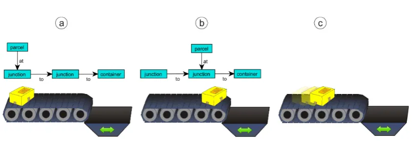
Figure 1: Existing approach: before GT (a), after GT (b) and animated scene (c)
formal/mathematical models like petri nets, educational languages like Alligator Eggs [SM09] and even highly interactive programming languages like the Alternate Reality Kit [Smi86].
It is a common approach to use graphs for representing such models in an abstract way. The model is changed by transforming the underlying graph via graph transformations (GT). Exist-ing techniques associate each graph (the graph before and after the GT) with a static model and therefore static visualization. An example in the domain of conveyor systems is shown in Fig-ure 1. While (a) shows the graph and its visual representation before the GT, (b) shows them afterwards. In order to avoid a jumping parcel in the visualization, the instantaneous GT can be stretched over time and a smooth animation is applied to the state transition (c).
This approach comes along with some obvious problems. If the system behavior includes multiple, independent animations in different parts of the model at the same time, specification becomes difficult. The problem becomes even more complicated if multiple animations overlap in time or if interactive environments shall be realized that way. As an instance consider the conveyor system where the container may move, too, and those movements might be triggered by user interactions. If such a user interaction takes place while a parcel is on its way as shown inFigure 1c, the system should immediately stop the conveyor with the parcel at the current position. However, this situation cannot be represented by the chosen graph.
This paper describes another approach: graphs represent the currently changing model and GTs are used to start, stop and modify animations. The rest of the paper is structured as follows:
Section 2describesAvalancheas a motivating example. Section 3 introduces the abstract ani-mation system, which serves as abstract formal system of the described approach inSection 4
using GTs. As an example,Section 5shows an application of this approach in order to specify
Avalanche.Section 6outlines related work, andSection 7concludes the paper.
2 Avalanche
Figure 2:Avalancheboard Figure 3:Avalanchepieces
The board of the game is an inclined plane. On this plane, there are multiple lanes, which are directed top-down. However, lanes can be interrupted by switches. Switches are placed in between two adjacent lanes. In this area, there is no border between left and right lane, and the switch can be tilted freely to the left or right. Shifted to one side, the switch can block the direct top-down way of the corresponding lane.Figure 2shows an exemplaryAvalancheboard.
The game is played by putting marbles on the start (top) of a lane. After putting a marble there, it rolls down along the lane. Figure 2(a) shows a position where a marble can be brought into play, and the marble starts rolling. While rolling down, a marble can be stopped by a switch that is facing the marble’s lane (b). Rolling along the opposite lane, the marble hits the bottom of the switch, and therefore tilts the switch to the other side like in (c). This feature can be used for releasing a marble that has been stopped by the switch. After this marble has been released, it continues to roll along its lane, as shown in (d). In this concrete situation, the switch is lying on the left side afterwards1. If a marble hits another marble that has been stopped by a switch like in (e), the rolling marble changes the lane, continues rolling, and releases the other, previously blocked marble. Finally, when a marble reaches the end (bottom) of its lane as shown in (f), it is removed from the board.
EachAvalancheboard consists of four types of building blocks (see Figure 3): Start (starts
each lane; marbles can be placed there),Straight(straight lane),Switch(can block rolling mar-bles and can be switched by rolling marmar-bles; each switch can be in the left or right position), and
End(end of each lane; marbles are taken out of the game there).
1Depending on theAvalanchevariant, it is also possible that the released marble immediately triggers the switch
3 Abstract Animation Systems
TheAvalanchegame is a continuous dynamic system. In order to describe its behavior, it is a
common approach to look on it as a discrete event system with specified events for the collision of marbles with switches, putting new marbles on the field, etc. In the time between these events, the marbles are moving over the board, which can be illustrated by an animated visual model. This section formalizesabstract animation systems(AASs), a particular kind of event-oriented systems, which is especially suited for interactive and animated visual languages. It is an abstraction of the animation approach using graphs and GTs described in the following sections.
The idea of defining a visual animated model by an AAS is to specify a state-transition-system that performs state transitions triggered by events at certain points in time. The visual represen-tation of a model is determined by the current state of the state-transition-system and the current time. That means, the visual representation just depends on the (continuously) proceeding time between two consecutive state transitions. State transitions are triggered by events. Events may have an external source, e.g., the user placing a marble at aStartpiece. Theseexternal events
may happen at any time. Other events, called internal events, happen because of the current state after a certain span of time. For instance, if a switch starts switching from right to left, the switch will hit its left border after a fixed span of time. For this purpose, an event
Switching-CompleteLeftis triggered, which stops the switching (cf.Section 5). Models usually consist of
different parts, each of them with more or less independent behavior (e.g., anAvalancheboard with several switches and marbles). States and events must appropriately reflect this composite structure.
In the following, AASs are introduced more formally. LetT represent the absolute time. For each point in timet∈T, letω >t and letTω =T∪ {ω}. For any setX, the power set ofX is
denoted byP(X).
Definition 1 Anabstract animation systemis a tupleA= (S,E,E,˜ s0,δ,τ,ε). S is theset of
states and s0 is the initial state, s0∈S. E is the set of all events, whereas ˜E ⊆E is the set
of internal events. E\E˜ denotes the set of external events. δ is the state transition function,
δ :S×E×T → P(S). τ and ε describe the occurrence of internal events, τ :S→ Tω and ε:S→P(E˜). Each of these sets may be uncountably infinite.
The abstract animation systemAis started in states0at some point in timet0. The execution ofAis expressed by the chronology of occurred states; state changes are triggered by occurring events (internal and also external) at certain points in time. Each execution can be described by
atrace
s0 e1
−→t
1 s1
e2
−→t
2 s2
e3
−→t
3 ···
ei
−→t
i si
ei+1
−→t
i+1 ···
of assumed statess0,s1,s2, . . .∈S. In each case, at the point in timeti (i>0), eventei occurs and triggers the state transition fromsi−1 tosi ∈δ(si−1,ei,ti). Eitherei∈ε(si−1), i.e., ei is an internal event, thenti=τ(si−1), orei∈E\E˜, i.e.,ei is an external event, thenti∈[ti−1,τ(si−1)].
certain span of time. This is reflected by functionεandτ. However, an external event may hap-pen at any time, i.e., possibly before the scheduled internal event. The external event triggers a state transition, and the previously scheduled internal event may be re-scheduled again, specified by functionsδ,ε, andτ.
Following the motivation at the beginning of this section, the visual representation of an ani-mated visual model with an AASAis avisualization function I:S×T →RwhereRrepresents all possible graphical illustrations. Given a traces0 e1
−→t
1 s1
e2
−→t
2 s2··· ofA, the visual
representa-tion of the model at any point in timetisI(s,t)wheresis the current state att, i.e.,s=sifor an appropriateisuch thatt∈[ti,ti+1).
4 Animations using Graphs and Graph Transformations
The AAS formalism has been introduced to clarify the concepts determining the behavior of visual animated models. It can be used for describing an animated system likeAvalanche, but it is less suited for actually specifying concrete animated languages. Instead, we use the widely spread approach of typed graphs for internally representing visual models. Existing meta-tools like DIAMETA[Min06], which are based on this approach (we do not distinguish plain graphs
from hypergraphs here), then allow for generating editing environments from the visual language specifications. These tools already represent the static structure of a visual model by typed attributed graphs; the visual representation of a model is just a view of this graph. We now augment these graphs such that they also represent the current model state according to the notion of AASs. The visualization function, as described in the previous section, again provides a view of the graph. However, it must take the continuously proceeding time into account when determining the visual representation of the animated model.
Because graphs are used for representing the AAS state, state transitions correspond to graph modifications. GTs are an obvious choice to perform and specify these modifications. In order to realize the state transition functionδ of the AAS using GTs, each event (type) is associated with a particular set of graph transformation rules. Whenever an event occurs, especially if this is an external event sent to the system, the associated rules are selected for application in order to change the graph and state of the system, resp. If an event carries additional information, e.g.,
theStart piece where the user has placed a new marble, this information must be passed as a
partial embedding morphism to the selected GT rules.
calculation of the next internal events can be realized as follows: Whenever a new AAS state is reached, i.e., when the graph is changed, a list of all possible internal events for each part of the system is computed. Only that event is selected that will happen first. This implicitly realizes ε andτ. If there is no unique first event, one of them is chosen nondeterministically. When the event is triggered at the scheduled point in time, or if an external event happens earlier, the graph will be modified, i.e., a state transition is performed, and the next internal event will be computed again.
As already described, triggering an external or internal event actually means performing a GT; a partial morphism selects where the GT is applied. For external events, the partial morphism is selected by the external source, e.g., by selecting theStartpiece where the user places a marble. For an internal event, however, the partial morphism must have been determined when the event has been “scheduled” after the last graph modification. So far, we have not yet discussed how these internal events get calculated. Actually, event (types) are associated with graph patterns together with additional application conditions, i.e., positive and negative application conditions as well as conditions on node and edge attributes as well as the current time. Each pattern de-scribes situations, in which this event type occurs. Therefore, the list of all possible internal events is found by searching for all embeddings of each of these patterns satisfying their appli-cation conditions. An additional evaluation rule, calledtime calculation rule, computes the point in time when the event will happen. The results of this rule are used to select the first scheduled internal event. The associated embedding determines where the event takes place. Hence, the left-hand side of the GT rule specifying the effect of the event must consist of the same pattern that specifies the event and whose embedding has already been found when scheduling the event. In summary, the specification of an internal event type consists of a graph transformation rule with application conditions and a related time calculation rule. An external event type can be specified with a rule only.
We have extended our meta-tool DIAMETA[Min06] such that not only static visual languages
can be specified, but also animated visual languages following the ideas described above. DIA
-METAallows for generating editing environments for visual animated models from such
speci-fications. The DIAMETAframework is now aware of events, and it manages an event queue that
is used to determine the next internal events. This event queue is actually built up and updated in a smart way based on changes of the graph model.
The specification of events in DIAMETAis not restricted to single GT rules. Graph
transfor-mation programs, which may consist of several rules, are used instead. The application of these rules is controlled by additional control programs which, e.g., may specify a sequence of rules or use more complex control operators likeapply as long as possible[Min02]. The availability of complex control programs allows for the specification of arbitrarily powerful GT transforma-tions although each single GT rule is just a simple SPO rule with optional negative application conditions.
5 Specification of Avalanche
This section outlines how visual animated models ofAvalancheare specified in DIAMETA. One
Figure 4:Avalancheeditor screenshot
(a) buildAvalancheboards and (b) play the game including the possibility to put marbles onto
theAvalancheboard and watch the progress of the system. A screenshot of the resulting editor
is shown inFigure 4. An animated example can be found online2.
Typed, attributed hypergraphs are used for representing models, i.e., animated diagrams. Each model component is represented by a hyperedge that visits the nodes representing the compo-nent’s attachment points. Model hypergraphs also contain relation edges (binary hyperedges), that stand for relationships between components, and further hyperedges (calledanimation edges
in the following) that are used for the representation of animation states only. More details about the usage of hypergraphs for the specification of visual languages (except hyperedges represent-ing animation states) can be found in [Min06].
The Avalanchemodel components are the ones shown inFigure 3with the hyperedge types
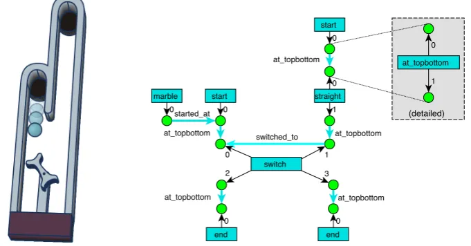
start, end, switch, straightand marble. Figure 5 shows an example Avalancheboard and its
model hypergraph. Each component is associated with its component hyperedge, which is de-picted by a filled rectangle each. Nodes are drawn as small circles. For instance, the switch
hyperedge is connected to individual nodes via connectors (“tentacles”) 0 to 3. The four nodes represent the top-left, top-right, bottom-left and bottom-right corners of the switch. Each of them can be connected to another model component. Connections between model components are represented by binary at topbottomrelation hyperedges. They are depicted by fat arrows. Additional edge types are used for animation edges representing the animation state, e.g., edge typesswitched toorswitching to. Theswitched toedge connects the first switch node with the
(detailed)
end end
marble start
start
straight
switch
at_topbottom
at_topbottom switched_to
at_topbottom at_topbottom
at_topbottom at_topbottom
started_at
0 0
0 0
0
0
1
0 1
2 3
0
1
Figure 5:Avalancheboard and corresponding hypergraph
second one if the right lane is blocked by the switch. If the left lane is blocked, the edge con-nects these nodes the other way around. Analogously, theswitching toedge indicates that the particular lane is not blocked yet, but the switch is currently moving in order to block the lane afterwards. There are also different edge types representing a marble’s state as explained later.
Furthermore, each component hyperedge has the layout attributesxandyfor the position of the represented diagram component. Finally, hyperedges which can be animated (resp. their corresponding components) contain an attributetc. It is used for storing the point in time when attributes of the hyperedge or its state have been modified lastly.
Static components and their visual appearance can be specified like in static DIAMETA. For
animated components, the specification is slightly different. There are two types of animations which are represented by a subgraph: a rolling marble and a shifting switch. Figure 6 shows two concrete graph examples which represent these animations: (a) represents a switch which is currently shifting from left to right. Theswitching toedge is an animation edge that represents the shifting state of the switch. The shifting animation has started at 20000 ms, which is indicated by attributetc. (b) represents a marble which is rolling. This animation has started at 3000 ms when the marble was at position(110,10). Thestarted atedge is again an animation edge which
specifies the animation state. The edge is not necessary for static diagrams, but it rather indicates the component where the marble was located when the animation started.
By using these attributes and animation edges, the animated appearance for a component de-pending on the proceeding timetcan be specified. For example, instead of drawing the marble at the static position(x,y), the position for each animation frame is calculated using the time
differencet−tcand a linear (or accelerated) movement. Further details about required constants (e.g., rolling speed of the marble, acceleration, relation points for positions) are omitted here.
So far, the described specification is sufficient for editable models with basic animations like rolling marbles or shifting switches. However, interaction between model elements or user in-teraction during animation have not been considered yet. In order to specify the Avalanche
marble
x = 110 y = 10 tc = 3000 ms switch
x = 100 y = 50 tc = 20000 ms
a b
start
x = 100 y = 0
0
0
started_at
0 1
switching_to
2 3
Figure 6: Hyperedges of animated components
straight switch
ps
switch
pe 0
1 0
2 at_topbottom
1
3
0
2
1
at_topbottom
3
at_topbottom
Figure 7: Example path
must be specified for the left and right side of switches separately3. Because the specification of both sides is analogous, rules for the right side are omitted.
• External events:
– PutMarble: The user selects astartcomponent in order to place a marble there.
• Internal events:
– MarbleStopLeft: A rolling marble hits the top of a switch (tilted to the left) and is
blocked.
– ReleaseMarble: A marble, blocked by a switch, is released and starts rolling down
because the switch does not block the lane any more.
– MarbleSwitchingLeft: A rolling marble hits the bottom of a switch (tilted to the right)
and initiates the shifting of the switch; during this shifting process, the switch cannot block marbles or be shifted again.
– SwitchingCompleteLeft: A shifting switch reaches its final destination after it has
started shifting from the right to the left side.
– MarbleChangeLaneLeft: A rolling marble starts changing the lane because it hits
another marble that is blocked by a switch tilted to the left.
– ChangeLaneCompleteLeft: A marble reaches its new lane after it has started
chang-ing its lane from the left to the right side.
– RemoveMarble: The marble reaches the end of the lane and is removed from the
board.
In the rest of this section, these events are described. Figure 8shows the event specifications by GT rules4 and, for internal events, time calculation rules (indicated by theTimekeyword). 3DIAMETAactually supports more generic specifications that cover both sides, but they are too technical and less
suited for presentation in this paper.
4Please note that these events are actually specified using single GT rules; the specification ofAvalanchedoes not
PutMarble (external event)
SwitchingCompleteLeft (internal event) m:marble
s:start
+++
+++
+++
m.tc := t m.x := s.x + C1 m.y := s.y + C2 Actions:
sw.tc := t
Time: Actions:
sw.tc + C5 sw:switch MarbleStopLeft (internal event)
m.tc := t m.y := sw.y + C3
Time: Actions:
m.tc + (sw.y - m.y + C3) / C0 (marble with constant speed) m:marble
x = s.x + C y = s.y + C tc = t
sw:switch
-+++
MarbleSwitchingLeft (internal event)
sw.tc := t
Time: Actions:
m.tc + (sw.y - m.y + C4) / C0 (marble with constant speed) m:marble
x = s.x + C y = s.y + C tc = t
sw:switch
+++
-RemoveMarble (internal event)
Time: m.tc + (e.y - m.y + C9) / C0 (marble with constant speed)
m:marble
x = s.x + C y = s.y + C tc = t
e:end
-ReleaseMarble (internal event)
Time:
m:marble
x = s.x + C y = s.y + C tc = t -NAC
n1 n1
+++
Actions:
MarbleChangeLaneLeft (internal event)
Time: m.tc + (sw.y - m.y + C6) / C0(marble with constant speed) m:marble
x = s.x + C y = s.y + C tc = t
sw:switch
m.tc := t m.y := sw.y + C6 Actions:
+++
-ChangeLaneCompleteLeft (internal event)
Time: m.tc + C8 m:marble
x = s.x + C y = s.y + C tc = t
sw:switch
m.tc := t m.x := sw.x + C7 Actions: +++ -+++ +++
(immediately if match is found) m.tc := t
0 0 started_at 2 3 0 1 switched_to switching_to 0 started_at 2 3 0 blocked path_down 1 switched_to 0 started_at 2 3 0 path_down 1 switched_to switching_to 0 started_at 0 path_down 0 switched_to blocked started_at 2 3 0 path_down 1 blocked 0 change_to started_at 2 3 0 1 0 started_at change_to
Figure 8:AvalancheEvent Specifications
DIAMETAactually uses a different, primarily textual syntax; the syntax inFigure 8is used for
illustration only. It shows the GT rule within one box: parts which are removed by the rule are drawn in red and marked with “- - -”, and parts which shall be added are drawn in green with “+++”. Attribute modifications are illustrated by expressions within a separateActionsbox. Please note that some expressions make use of constants starting with letterC; these constants represent specification details, e.g., rolling speed, relation points for positions, etc.
environment). The selectedstart component is then used for defining a partial match for the pattern of the graph transformation rule specified for PutMarble. The result of the rule is a created marble, which starts rolling down the lane.
SwitchingCompleteLeft is a simple internal event. Events of this type occur for each switch
edge with aswitching toanimation edge as shown in the pattern, i.e., for each switch which is currently shifting from the right to the left side. The time of the corresponding event is deter-mined by a simple formula indicating that the switch has reached the final destination after a constant amountC5 of time. Hereby, the value in attributetcrepresents the point in time when the corresponding switch started shifting (triggered by eventMarbleSwitchingLeft, see below). As a result, theswitching toedge is replaced by aswitched toedge.
MarbleStopLeft is a more complex event specification because it has to describe a rolling
marble hitting a blocking switch in the marble’s lane. The lane can go through a number of
start,straight, andswitchcomponents. In the event specification, this is represented by a dashed
arrow indicating a path within the model hypergraph. The path is actually an arbitrary sequence
ofat topbottom(0,1),switch(0,2),switch(1,3), orstraight(0,1)elements. Thereby, the numbers
in parenthesis specify the hyperedge tentacles the path must follow: the first number specifies the ingoing tentacle and the second one specifies the outgoing tentacle when following the path through hyperedges. An example path is shown inFigure 7: the path starts at nodepsand ends at nodepe. In a matching scenario ofMarbleStopLeft, themarbleedge must be linked topsvia
thestarted atedge, andpeis the node of the first outgoing tentacle ofswitchedgesw.
The time of the eventMarbleStopLeftis calculated based on the distance between the rolling marble and the switch. As a result of this event, the marble looses itsstarted at relation and receives ablockededge instead, which indicates the marble being blocked by the switch. More-over, the marble’s static position is set to the position of the switch.
EventMarbleSwitchingLeft is similar and also makes use of path expressionpath down de-scribed above. The switch, however, does not block the rolling marble’s lane, indicated by the
switched toedge having the opposite direction of the one in eventMarbleStopLeft. If this event
occurs, the marble continues rolling normally, but it also shifts the switch. The switch state is changed by replacing theswitched toedge by aswitching to edge, now being associated with the opposite side/lane. Nevertheless, the switch is not considered blocking this lane yet. The end of this shifting phase will trigger a newSwitchingCompleteLeftevent (see above).
The event ReleaseMarblecan occur directly after aMarbleSwitchingLeft(or
MarbleSwitch-ingRight, resp.) event. TheReleaseMarbleevent does not specify a time calculation rule and,
therefore, is applied immediately as soon as a match is found. It releases a blocked marble if the switch does not block the according lane any more. The marble then starts rolling down again, indicated by the animation edgestarted at.
The internal eventMarbleChangeLaneLefthandles the case that a rolling marble hits a blocked marble. The rolling marble then changes its lane, which is indicated by achange toedge linked to the switch node of the opposite side. This changing process ends as soon as event
Change-LaneCompleteLeft occurs after a constant amount of time. The marble then continues rolling
down again, however in the switch’s other lane.
6 Related Work
Another approach of simulating and animating visual languages is described in [Erm06]. How-ever, the described methods come along with some of the issues mentioned in the introduction of this paper. The resulting animations are self-running movies, and amalgamated graph transfor-mation rules are already required for the specification of less complex examples like animated petri nets, for instance.
The described abstract animation system is similar to timed event systems and, therefore, also toDEVS [ZPK00]. However, abstract animation systems omit some specific features like ac-ceptance stated (compared to timed event systems in general) or output function (compared to
Atomic DEVS). On the other hand, the intention of abstract animation systems is that system
states can be visualized in an animated way, and state changes start, stop, and change these ani-mations. It allows for an easier specification of systems which must be animated and illustrated.
In [SH08] Atomic and Coupled DEVS are used as a formalism for the implementation of
dynamic systems applying graph transformations. However, the work is focused onDEVS as semantic model for programmed GTs rather than animations. It depends on GTs consuming time and on special control structures within theDEVSmodel in order to support parallel executions and interruptions.
Section 5 shows that there is a need for a time attribute like tc within graph vertices for many types of animation. This attribute can be compared with an attributechronosintroduced in [GHV02] which describes an approach of graph transformation with time. The shown trans-formations utilize logical clocks, which are also represented by the mentioned vertex attribute.
Another, but similar approach, though not based on GTs, is shown in [EVV09]. This work describes a transformation system enriched by parameters like duration, repetitions and focuses on the visual notation of such rules.
The idea of states describing animation and behavior of graphical objects is a common ap-proach. The termanimation statehas also been described in [Vit05] where it represents a state in which corresponding object attributes are changing with regard to animations. The work also shows how animations and the behavior of object can be described by a visual language based on UML2 statecharts.
7 Conclusions
The specification of animated visual languages based on graphs has been limited with regard to simultaneous, independent animations and interactivity yet. The described approach enables dynamic, animated and interactive models using existing graph and graph transformation tech-niques. After minor extensions, the existing meta-tool DIAMETA is able to generate editing
environments for interactive animated visual models likeAvalanche.
cal-culation rules must be written by hand. Animation patterns for common animation types would be desirable, and also a physics engine or other frameworks could be used in order to simplify specification of particular kinds of animated visual languages.
Bibliography
[Erm06] C. Ermel.Simulation and Animation of Visual Languages based on Typed Algebraic
Graph Transformation. PhD thesis, Tech. Univ. Berlin, Fak. IV, Books on Demand,
Norderstedt, 2006.
[EVV09] J. Eduardo Rivera, C. Vicente-Chicote, A. Vallecillo. Extending visual modeling lan-guages with timed behavioral specifications. InIDEAS 2009: Proc. 12th
Iberoameri-can Conf. on Req. Engineering and Software Environments. Pp. 87–100. 2009.
[GHV02] S. Gyapay, R. Heckel, D. Varr´o. Graph Transformation with Time: Causality and Logical Clocks. InICGT ’02: Proc. 1st Int. Conf. on Graph Transformation. LNCS 2505. Pp. 120–134. Springer-Verlag, 2002.
[LV02] J. de Lara, H. Vangheluwe. AToM3: A Tool for Multi-formalism and Meta-modelling.
InFASE ’02: Proc. 5th Int. Conf. on Fundamental Approaches to Software
Engineer-ing. LNCS 2306. Pp. 174–188. Springer-Verlag, 2002.
[Min02] M. Minas. Concepts and Realization of a Diagram Editor Generator Based on Hyper-graph Transformation.Science of Computer Programming44(2):157–180, 2002. [Min06] M. Minas. Generating Meta-Model-Based Freehand Editors. InProc. of the 3rd Int.
Workshop on Graph Based Tools (GraBaTs’06), Satellite of ICGT’06. Electronic
Communications of the EASST 1. 2006.
[SH08] E. Syriani and H. Vangheluwe. Programmed Graph Rewriting with DEVS. In Appli-cations of Graph Transformations with Industrial Relevance: 3rd Int. Symp., AGTIVE 2007. LNCS 5088. Pp. 136–152. 2008.
[SM09] T. Strobl, M. Minas. Implementing an Animated Lambda-Calculus. InWorkshop on
Visual Languages and Logic, Satellite of VL/HCC’09. CEUR Workshop
Proceed-ings 510. 2009.
[Smi86] R. B. Smith. The Alternate Reality Kit: An Animated Environment for Creating Inter-active Simulations. InProc. of the 1986 IEEE Computer Society Workshop on Visual
Languages. Pp. 99–106. 1986.
[Vit05] A. Vitzthum. SSIML/Behaviour: Designing Behaviour and Animation of Graphical Objects in Virtual Reality and Multimedia Applications. InProc. Seventh IEEE Int.
Symp. on Multimedia (ISM’05). Pp. 159–167.