Model test study on cracking condition and propagation path of main structural plane tip in
compression-shear type of perilous rock
Jingyu Zhang1*, Zuosen Luo2, Guoyong Duan3
1 College of Hydraulic & Environmental Engineering, China Three Gorges University, Yichang 443002, China 2 College of Civil Engineering & Architecture, China Three Gorges University, Yichang 443002, China 3 College of Civil and Transportation Engineering, Hohai University, Nanjing 210098, China
Corresponding Author Email: [email protected]
https://doi.org/10.18280/eesrj.050202 ABSTRACT
Received: 10 April 2018 Accepted: 6 June 2018
Aiming at the compression-shear damage type perilous rock, I establish a uniaxial compression test indoor to research how different inclined angles’ and lengths’ of main structural plane impact on the fracture critical stress of test sample and propagation path of crack. The study shows that: when main structural planes of samples have the same length, the fracture critical stress of test sample increases along with the increasing of main structural plane’s inclined angle; when main structural planes of samples have the same inclined angle, the fracture critical stress of test sample decreases along with the increasing of structural plane’s length. The branches of crack include wing crack, collinear crack and inclined crack. The collinear crack appears frequently, the wing crack follows and the inclined crack appears rarely. In addition, the wing crack’s propagation angle relatively conforms to the angle of maximum circumferential stress criterion. According to experimental research on main structural plane tip propagating in compression-shear damage type perilous rock, I acquire regularity which has positive significance to further study on main structural plane tip extending in other types of perilous rock.
Keywords:
perilous rock, compression-shear damage, main structural plane; model test, crack condition
1. INTRODUCTION
Perilous rock is a type of rock, and its rock mass is basically incised by structural planes. It is also characterized by sudden, rapid and devastating stability problems [1]. More than 8000 failures per year have been occurring in China due to perilous rocks. The direct economic loss caused by perilous rock in china over the period of one year is almost 5 billion Yuan. Therefore, it becomes fundamental for practicing engineers in their day-to-day practice to consider failures attributed to perilous rock. The failure mechanism of perilous rock is a key for the theoretical basis. Therefore, detailed scientific investigations are still needed for the better understanding of perilous rock.
The formation of perilous rock, the fracture propagation of structural plane and perilous rock collapse are the mechanical mechanism of rock slope landforms evolution. Hence, the formation of perilous rock and the fracture propagation of structural plane belong to the mechanical process of continuous gradient. In this regard, plenty of studies have been done in the past. Chen Hong-Kai et al. discussed the setting for the formation of perilous rock failures [2]. [The damage characteristics of structural plane tips on the perilous rock were studied by Chen Hong-Kai et al. based on fracture and damage mechanics [3].Similarly, the nature of fatigue failure under fissure water pressure has been studied [4]. In the past, researchers [5] developed a method to analyze the fracture stability of perilous rock. The potential impact due to rock fall and the dynamic parameters of the perilous rock were studied by [6] and [7] respectively. Others [8] showed the sequence of
perilous rock failure at the escarpment. Zhang Yong-Xing et al. investigated the effect of ground stress on the rock slope. Besides, they have studied the effect of cave deepness on the differential weathering of overhanging rocks [9].
G. C. Sih et al. examined the relationship between the compound crack and the strain energy density factor, and they proposed the fracture criterion [10]; M. A. Tasdemir et al. compared the crack fracture angle by using a prefabricated crack from the cement mortar samples under the compression test condition [11]. Zhao Yanhua used the second stress invariant J2 as a basis of making a judgment to predict the crack fracture angle and the corresponding load [12]; Kulatitake PHSW et al. discussed the mechanical characteristics of the rock mass structure based on cleavage rock mass mechanics [13]; S. Stoychev et al. scrutinized the effects of stress and stress intensity factors on the crack propagation of the crack tip [14].
The fracture of the main structural plane leads the perilous rock to collapse and its failure mode is usually divided into two types, compression-shear failure and tensile-shear failure. The main structural plane of the perilous rock has a lower mechanical strength. The angles of inclination and the lengths of main structural plane govern the critical stress and the main structural plane propagation in the perilous rock. After analyzing the experimental results, important findings were pointed out. And it was believed that, the conclusions made in this paper will have a significant contribution for further study.
Environmental and Earth Sciences Research Journal
Vol. 5, No. 2, June, 2018, pp. 42-47
2.MODEL TEST
The prime objective of this paper is to study the compression-shear failure of perilous rock. Based on the expected failure modes of perilous rock in compression-shear failure, the test model was established. The following key points were studied in this paper: 1) the effects of angles of inclination and the lengths of main structural plane on the critical stress at failure. 2) the main branches, the propagation path and the stress analysis of the main structural plane and some other related theoretical analysis.
2.1. Sample preparation
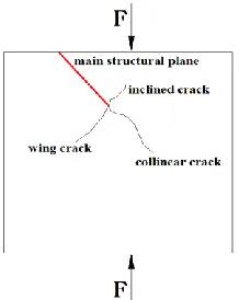
Based on the practical situation observed on the field (Fig.1a), the test model for the compression-shear failure test was prepared (Fig. 1b).
(a) Practical example (b) physical model
Figure 1. Practical example and physical model
Figure 2. Experimental model
As shown in Fig. 2, the diagonal crack was considered as the main structural plane of the perilous rock. The cube size of the model was 150mm x150mm x 150 mm. Moreover, the Proportions of cement mortar are listed in Tab.1.
Table 1. Proportion of cement mortar
Grades of cement (MPa) 42.50
Weight of per cubic meter (Kg) water cement sand
310 430 1290
Mix proportion 1.39 1.00 3.00
Sand content (%) 63.55
The mechanical properties of these samples are listed in Table 2.
Table 2. Proportion of cement mortar
Compressive strength(MPa)
Tension (MPa)
Weight (kN/m3)
Elastic modulus(GPa)
Poisson ratio
16.83 0.89 20.13 3.37 0.19
2.2. Test design
Table 3. Samples used in the testing program
length angle
30mm (group A)
45mm (group B)
60mm (group C)
40° A1 B1 C1
50° A2 B2 C2
60° A3 B3 C3
70° A4 B4 C4
80° A5 B5 C5
Three testing groups were formed based on the lengths of the inclined crack. Group A, B and C stand for 30mm, 45mm and 60 mm crack length respectively. Besides, five different angles of inclination (40°, 50°, 60°, 70° and 80°) have been used for each group. Therefore, a total of 15 samples were prepared to simulate the above conditions (Table 3).
3. RESULTS AND ANALYSIS
3.1 The critical loads and stresses of the fractured samples
During the test, the critical load and the stress were recorded at failure. The actual test data are presented in Table 4, Table 5 and Table 6.
Table 4. Critical loads and stresses (Group A)
Sample
number A1 A2 A3 A4 A5
Critical load (kN)
112.3
2 118.98 129.78 140.94 142.92 Critical
stress (MPa)
6.24 6.61 7.21 7.83 7.94
Table 5. Critical loads and stresses (Group B)
Sample
number B1 B2 B3 B4 B5
Critical load
(kN) 93.78 102.96 110.16 122.58 128.52 Critical stress
(MPa) 5.21 5.72 6.12 6.81 7.14
Table 6. Critical loads and stresses (Group C)
Sample
number C1 C2 C3 C4 C5
Critical load
(kN) 70.38 77.76 94.86 111.42 123.30 Critical stress
(MPa) 3.91 4.32 5.27 6.19 6.85
3.2 Influence of main structural plane length and angle of inclination on the critical stress
Figure 3 shows the relationship between the critical stress and the angle of inclination under a particular structural plane length.
when the angle of inclination varied from 50° to 70°, the critical stress was increasing dramatically.
Figure 3. The relationship between the critical stress and the angle of inclination
Similarly, Figure 4 illustrates the relationship between the critical stress and the length of structural plane under a given angle of inclination.
Figure 4. The relationship between the critical stress and the main structural plane length
In the other case, the critical stress was decreasing when the length of structural plane increased (Figure 4).
Considering the above two cases: (1) the samples were more resistant to fracture while the angle of inclination was increasing under a constant structural plane length, (2) the samples got more resistance to fracture when the length of structural plane was deceasing under a constant angle of inclination.
3.3 Propagation path of the main structural plane tip
Under the uniaxial compression test, there will be a development of various branch cracks at the tip of the main structural plane. The crack patterns of the specimen are presented in the Figures below (from Figure 5–Figure 7).
Figure 5. Propagation path of structural plane tip (Group A)
Figure 6. Propagation path of structural plane tip (Group B)
Figure 7. Propagation path of structural plane tip (Group C)
Nowadays, Feng (2002) have been studying the crack propagation in rocks. Many of their findings are agreed with the existing crack propagation mechanism. In this study, three types of cracks (i.e., wing, collinear and inclined cracks) were observed as shown in Figure 8.
Wing cracks are tensile cracks. These types of cracks initiate at or near the tips of structural plane and propagate towards the direction of maximum compression. However, collinear cracks are shear cracks and quasi-coplanar with the main structural planes. To come to the inclined cracks, they are quite similar with the wing cracks. But, their direction of propagation is opposite to the wing cracks.
Table 6. Types of branches and angles formed with the main structural planes (Group A)
Branch Wing crack Collinear crack Inclined crack Sample
number
With or without Angle
With or without Angle
With or without Angle
A1 ● 97° ● -13° ○ ○
A2 ○ ○ ● 9° ○ ○
A3 ○ ○ ● 4° ○ ○
A4 ○ ○ ● 12° ● -50°
A5 ○ ○ ● -9° ○ ○
Table 7. Types of branches and angles formed with the main structural planes (Group B)
Branch Wing crack Collinear crack Inclined crack Sample
number
With or
without Angle
With or
without Angle
With or
without Angle
B1 ○ ○ ● 20° ○ ○
B2 ○ ○ ● 27° ○ ○
B3 ○ ○ ○ ○ ● -43°
B4 ● 76° ● -16° ○ ○
B5 ● 46° ○ ○ ● -49°
Table 8. Types of branches and angles formed with the main structural planes (Group C)
Branch Wing crack Collinear crack Inclined crack Sample
number
With or
without Angle
With or
without Angle
With or
without Angle
C1 ○ ○ ● 23° ○ ○
C2 ● 93° ● -3° ○ ○
C3 ○ ○ ● -6° ○ ○
C4 ○ ○ ● 17° ○ ○
C5 ● 83° ● -5° ○ ○
Note: ● means have; ○ means none
The statistics regarding to the types of branches and the angles formed with the main structural planes are listed in Table 6-Table 8.
Based on the above data the following points can be pointed out.
(1) Out of 15 samples: 13 samples developed collinear cracks. The other 5 and 3 samples developed wing and inclined cracks respectively.
Under a uniaxial compression, the collinear cracks developed predominantly. However, the wing and inclined cracks developed less frequently and rarely.
(2) Moreover, collinear and wing cracks formed flexural and smooth propagation path respectively. During the propagation process of collinear cracks, the conversion or the combined effect of shear and compression stresses yielded flexural path. For example, the initial crack angle (considering collinear crack) for sample A1 and B4 were -13° and -16° respectively.
In the case of wing crack, the area beneath the tip of the main structural plane was under tension and the resulted propagation path was smooth. For example, the initial crack
angle (considering wing crack) for sample A1, B5 and C2 were 97°, 46° and 93° respectively.
4. DISCUSSION
Initial Crack Angle of Wing Crack: Sih (1974) proposed the maximum axial normal stress criterion in 1963. This criterion states that crack propagates in the direction of the maximum axial normal stress, σθ, and it develops when the maximum axial normal stress, σθ reaches its critical value, σθ max (Figure 9).
Figure 9. The crack tip propagation model
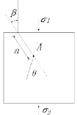
After setting up the model and conducting the test, the main structural plane was analyzed as shown in Figure 10.
Figure 10. The mechanics model for analysis
For the compound (first and second) type of crack fracture problems, the maximum axial normal stress in the main structural plane tip is:
(
)
1 2
1 1 3
= K cos 1+ cos - K cos sin
2 2 2 2
2 r
(1)
In the equation above, K1 and K2 are the stress intensity factors for the first and the second type of cracks.
The maximum axial normal stress criterion could simply be expressed as follows:
(2) Obtaining the equation
1 2
K sin + K 3cos - 1 =0 ( ) (3)
(4)
Due to the variations in the thrust surface area (i.e., at the top and at the bottom), the resulting stresses were also different. Hence, the stress which has a higher value (σ1) was taken.
Substituting equation (4) into equation (3) results,
2
2 3-cot 8+cot cos =
9+cot
(5)
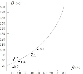
In the meantime, the relationship of θ-β is showed in Figure 11.
It can be clearly seen that (Figure 11), the fracture angle was reaching 180o when β and angle of inclination were 90° and 0° respectively. Similarly, for β=0° and angle of inclination=90°, the corresponding fracture angle was 70.5°.
The wing crack was developed due to tension. The maximum axial normal stress criterion states that crack propagates in the direction of the maximum axial normal stress, σθ. As it can be seen from Figure 11, the wing crack angles for sample A1, C2 and B4 were conformed to the theoretical values obtained from the maximum axial normal stress criterion. However, the wing crack angles for sample B5 and C5 were slightly deviated from the theoretical values obtained from the maximum axial normal stress criterion.
Figure 11. The relationship of θ-β
5. CONCLUSIONS
(1) There was a slight increment in the critical stress over the initial range (i.e., between 40° to 50°) and the final range (i.e., between 70° and 80°) of angle of inclination under a given structural plane length. However, when the angle of inclination varied from 50° to 70°, the critical stress was increasing dramatically.
(2) The fracture critical stress was decreasing when the structural plane length increased under a certain angle of inclination.
(3) In the uniaxial compression test, the collinear cracks developed predominantly. However, the wing and inclined cracks developed less frequently and rarely.
(4) The propagation path of wing crack was smooth, that is mainly caused by the development of tension around the main structural plane tip. However, in case of collinear cracks, the conversion or the combined effect of shear and compression stresses yielded flexural path.
(5) The wing crack angles obtained from the testing program were conformed to the theoretical values obtained from the maximum axial normal stress criterion.
ACKNOWLEDGMENT
This research was supported by the national natural science fund project (51439003) and the fundamental research funds for the central universities of Hohai University (2016B43014).
REFERENCES
[1] Chen HK, Tang HM, Wang LF. (2009). Evolutionary theory and application of perilous rock collapse. Beijing: Science Press.
[2] Chen HK, Xian XF, Tang HM. (2010). Developing Mechanism for Collapse Disaster in Rocky Mountain Area. Journal of Sichuan University (Engineering Science Edition) 42(3): 1-6.
[3] Chen HK, Tang HM, Ye SQ. (2006). Damage model of control fissure in perilous rock. Applied Mathematics and Mechanics 27(7): 967-974.
[4] Chen HK, Tang HM. (2007). Method to calculate fatigue fracture life of control fissure in perilous rock. Applied Mathematics and Mechanics 28(5): 643-649.
[5] Chen HK, Xian XF, Tang HM. (2009). Stability analysis method for perilous rock by fracture mechanics. Journal of Chongqing University 32(4): 434-437.
[6] Tang HM, Wang Z, Xian XF, Chen HK. (2011). Violent-slide rock avalanche and excitation effect of perilous rock. Journal of Chongqing University 34(10): 39-45. [7] Chen HK, Zhang RG, Tang HM, Zhao XT. (2012).
Elastic & impulsive dynamic parameters of a ruptured compression-shear perilous rock. Journal of Vibration and Shock 31(24): 33-36.
[8] Tang HM, Wang LF, Chen HK, Xian XF. (2010). Collapse sequence of perilous rock on cliffs with soft foundation. Chinese Journal of Geotechnical Engineering 32(2): 205-210.
[9] Zhang YX, Lu L, Zhang SP, Hu DW. (2010). Development and failure principle of differential weathering overhanging rock. Journal of Civil, Architectural & Environmental Engineering 32(2): 1-6. [10] Sih GC. (1974). Strain-energy-density factor applied to
mixed-mode crack problems. International Journal of Fracture 10(3): 305-321.
[11] Tasdemir MA, Maji AK. (1990). Crack Propagation in Concrete Under Compression. Eng. Mech. 116: 1058-1076.
[12] Zhao YH, Xu SJ. (2002). I-II compound crack the smallest J2 criterion of brittle fracture. Engineering Mechanics 19(4): 94-98.
[13] Kulatitake PHSW, Balasingam P, Jinyong P, Morgan R. (2006). Natural rock joint roughness quantification through fractal techniques. Geotechnical and Geological Engineering 24(5): 1181-1202.
NOMENCLATURE
1
K the stress intensity factors for the I type of cracks
2
K the stress intensity factors for the II type of cracks
Greek symbols
the maximum axial normal stress
critical angle