Big blue goes down. The Miller Park crane accident
Bernard Ross
*, Brian McDonald, S.E. Vijay Saraf
Exponent Failure Analysis Associates, 149 Commonwealth Drive, P.O. Box 3015, Menlo Park, CA 94025, USA
Received 30 August 2006; accepted 1 December 2006 Available online 7 February 2007
Abstract
The catastrophic collapse of Big Blue on the Milwaukee Brewers baseball stadium retractable roof project could be the most awesome lift accident of all time. The crane, a Lampson TransiLift III with a 340 ft main boom and a 200 ft jib, was setting a 100·180·16 ft open truss panel roof section weighing close to 500 tons at a lift height of 230 ft. With 11 diesel engines, 6 miles of wire rope and 1150 ton counter weight, the 2100 ton crane was a massive machine, indeed. The accident occurred during 26 mph average winds with gusts in the mid 30’s. Three ironworker fatalities and hundreds-of-million dol-lar damages resulted from this mishap. The ensuing litigation pitted co-defendants Mitsubishi Heavy Industries, the crane lessee/operator versus Lampson, the crane designer/builder, on totally disparate theories for cause and origin of the failure. The paper describes the comprehensive engineering analyses undertaken to disprove the Mitsubishi theories of failure as confirmed by jury verdict. Among the topics discussed are: wind tunnel testing, structural analyses of the boom, metallurgy of failed parts from a critical king-pin assembly, and soils engineering work related to ground loads and displacements during the lift. Crucial role of the SAE J1093, 2% design side load criterion and Lampson’s justification for an 85% crawler crane stability criterion are presented.
2006 Elsevier Ltd. All rights reserved.
Keywords: Crane overturn; Wind loads; Ground stability; Miller Park; Milwaukee fatal crane accident
1. Introduction
The catastrophic collapse of Big Blue on the Milwaukee Brewers baseball stadium retractable roof project (Miller Park) could well be the most awesome lift accident of all time. The mishap happened whilst the crane, a Lampson Transi-Lift III, was setting a 190 ft·130 ft·12 ft open truss panel roof section weighing close to 500 tons at a load radius and lift height of 155 ft and 230 ft, respectively. The crane mounted a 340 ft main boom and 200 ft jib making it the second highest structure in Wisconsin. With 11 diesel engines, 6 miles of wire rope and 1150-ton (US) counter weight, the 2100-ton crane was a massive machine, indeed.
The accident occurred during 26 mph average winds with gusts in the mid 30’s. Three ironworker fatalities, five serious personal injuries, and damage claims in the 500 million dollar bracket resulted from this calamity. The ensuing litigation for the wrongful death actions pitted co-defendants Mitsubishi Heavy Industries, the
1350-6307/$ - see front matter 2006 Elsevier Ltd. All rights reserved. doi:10.1016/j.engfailanal.2006.12.002
* Corresponding author. Tel.: +1 650 688 7200; fax: +1 650 328 2995. E-mail address:[email protected](B. Ross).
roof designer, fabricator and erector, and also the crane lessee/operator versus Lampson, the crane designer and owner, on totally disparate theories for cause and origin of the ‘‘Failure’’ which precipitated the accident. The present paper describes the comprehensive engineering analyses undertaken by Exponent Failure Anal-ysis Associates and allied consultants to disprove the adversary theories of failure as confirmed in a 100 million dollar jury wrongful death verdict against Mitsubishi. Among the topics discussed are: wind tunnel testing per-formed on model sections of the crane and roof, stability studies related to crane overturn, structural analyses of the boom, metallurgical investigations, stress related calculations of failed parts from a critical king-pin assembly and soils engineering work concerned with loads and displacements of the ground support system during the lift.
2. The accident
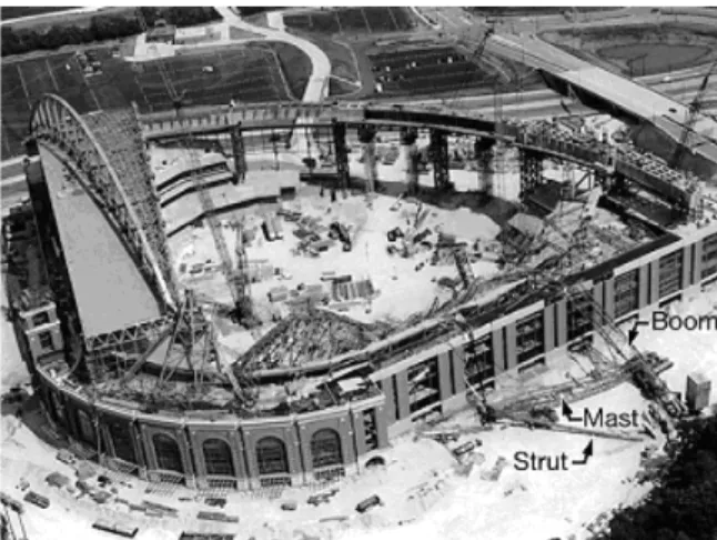
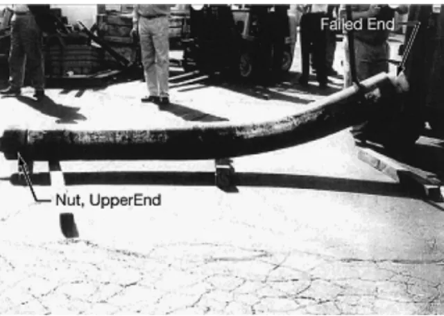
The accident occurred July 14, 1999 during the late afternoon hours. As noted, winds were exceptional with mean and gust speeds at 22–24 and 32–34 miles per hour, respectively. An amazing, even serendipitous, fea-ture of the accident was that it was videotaped in its entirety. The tape shows clearly that a flag mounted on an upper reach of the stadium is unfurled and flying straight in a brisk south wind. The accident sequence begins with a very large bang. A second bang, about four seconds later, occurs at same time as discernible motion of the crane boom and jib with suspended roof panel load is observed downwind. At this point, the front crawler driver has bailed from the operator compartment and is running for his life. The offside (west) crawler track is raised perceptibly above the ground. Then a third bang of less intensity is heard, whereupon a dirt cloud is
Fig. 1. Post accident scene.
seen to emerge from under the carbody, just as 500 tons of boom and roof panel crash into the already erected fixed roof sections of the stadium. Photographs of the aftermath are shown inFigs. 1 and 2.
3. The crane
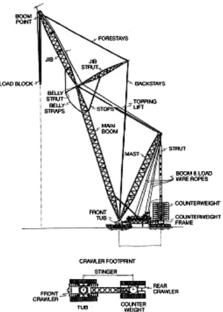
A schematic drawing of the Lampson LTL 1500, Series IIIA, Transi-Lift crawler crane is shown inFig. 3. The essential lifting apparatus includes a 340 ft boom and a 200 ft jib, supported by a 110 ft fixed angle jib strut through forestay and backstay connections to a tub mounted on the front (carbody) crawler base. Luf-fing (topping) of the boom is accomplished via a 190 ft mast, pinned at top end to a vertical tubular strut, which is anchored on a separate rear crawler base that supports the 1150-ton counterweight. The front crawler is connected to the independently driven rear crawler by a 100-ft extensible stinger which carries the operator platform, main hoist drum and topping line (boom hoist) drum. The boom, jib, jib strut, mast and stinger are all lattice truss structures whereas the counterweight strut is a tubular member. The two crawler bases, driven by individual operators in radio contact, provides the means for crane swing (slewing) motion whereby the rear crawler walks the pivoted front tub around its own crawler base (carbody).
The use of two crawler bases interconnected by a stinger, acting as a giant lever arm, to produce slewing rotation of the crane (yaw) avoids the need for swing drive machinery. Thus, the means of location for the crane upperworks, or tub, with respect to the lower crawler base is simply accomplished with a king pin as a centering device, whereas total dead weight of the upperworks and live load are carried on a 14 ft diameter, 16 in. wide, annular Teflon thrust bearing ring. The king pin is 12 in. diameter, 11 ft long and weighs, with ancillary hardware, about 4500 lb.
The king pin is held in place at its upper end by a heavy nut and locking ring. The lower end, underneath the carbody, mounts an assembly of parts including, from top to bottom: an embedded bronze flanged bush-ing (‘‘top hat’’), a bronze annular spacer rbush-ing and a bulky steel split rbush-ing retainer in two halves, fixed in place
by an annular locking ring with cap screws. The split retainer halves fit into the king pin via a 2–15/16 in. wide, 1-in. deep radial groove of rectangular cross section. A schematic drawing of this arrangement is shown in
Fig. 4.
The crane stability condition is such that the requisite 2% side load design criterion (i.e., 2% of rated main hoist load) can be satisfied wholly by dead weight of the crane upperworks whereby the king pin experiences no transverse and/or bending loads whatsoever during all normal operations. Thus, the kingpin serves essen-tially as a centering or pivot axis for swing (slewing) rotations. In theory, all of the bottom end fixation hard-ware could be omitted; however, as a matter of conservative engineering practice, and for tub-carbody interactive adjustments (stack-up), the need for these components becomes obvious.
The Lampson Transi-Lift was designed in accord with the basic USA Standard safety code for crawler cranes, USAS (ANSI) B30.5-1968, and in conformance with OSHA, Rules and Regulations, Section 1910.180. The requisite engineering references for the structural design criteria were: SAE J987, Rope Sup-ported Lattice-Type Boom Crane Structures-Method of Test and SAE J1093, Latticed Crane Boom Sys-tems-Analytical Procedure. Crane stability was governed by SAE J765, Crane Load Stability Test Code. Design analysis for the boom and jib lattice structures acknowledged the following loads: all structural truss works’ dead weights, boom elevation (i.e., topping) and main load suspension rope weights, boom and hoist rope tension forces at rated loads, boom foot pin inclination, hoist drum offset and most importantly with respect to the present accident, boom point side load at two percent (2%) of rated load. Allowable wind loads were calculated using ANSI A58 1-1972—Minimum Design Loads in Building and Structures (Wind loads). Structural design acceptance criteria for the boom were based on AISC stress levels with respect to yield, boom point tip deflection, and both Euler column and local buckling strengths. P-Delta offset effects were included in the structural assessment. The limiting case for the lift that figured in the present accident was boom tip deflection at a capacity chart rated load of 1040 kips.
In sum, the patented Lampson Transi-Lift configuration can be described as a crane featuring the high capacity characteristics of stiff leg and luffing derricks coupled with the mobility of a conventional crawler crane. The crane is capable of all lift functions including hoist, boom, swing, and travel with loads. Because all loads supported by the jib and main boom converge and are transmitted to the tub centreline (i.e., center of rotation) via the backstays and mast, there results uniform ground load at the crawler tracks for all swing
Fig. 4. King pin lower end fixation details.
Table 1
Crane specifications
Lampson LTL-1500, Series IIIA, Transi-Lift Main boom, 340 ft; Jib 200 ft; Jib strut, 110 ft Mast, 190 ft; offset, 10; stinger, 100 ft
Crane weight, 2100 ton; counter weight, 1150 ton Rated capacity, 1500 ton @ 85% tipping factor Power, 11 Diesel engines; rigging, 6 miles wire rope
(slew) and boom angles. This situation is unlike the ground load distribution pattern consonant to a conven-tional crawler crane where the boom foot pins are offset from the crane centre of rotation and stability margins are lower for lifts over the side. In this context, Lampson can gain advantage from a rated capacity chart based on 85% tipping loads versus the 75% limit imposed on conventional crawler cranes. Pertinent specifications of the Lampson Transi-Lift crane are summarized inTable 1.
4. The load
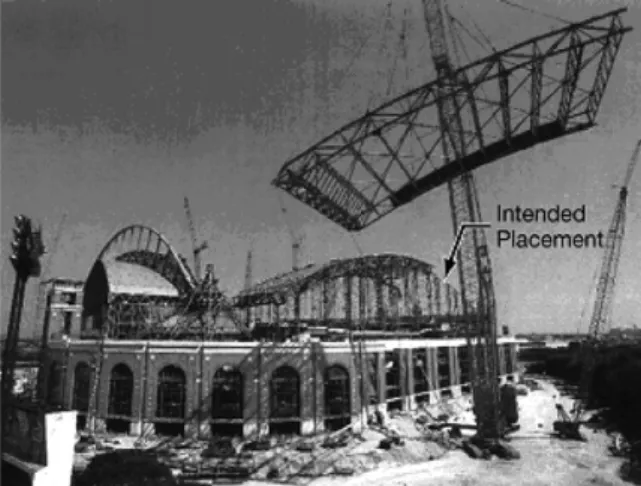
The load being hoisted at time of the accident was an immense curved panel section which formed part of the fixed roof structure along the first base, right field foul line of the stadium. The roof panel, designated 4R3, was a tied arch deep truss comprised of 300 members which together with rigging and blocks weighed in at approximately 510 tons. Steel for the roof sections was rolled in Luxemburg, shipped to China for primary welded fabrication into modules, then joined in final assembly at the ballpark site. The 4R3 roof section truss is shown inFig. 5.
Fig. 6presents an imposing view of the entire truss section at 330 ft elevation during the 350 ft carry-travel sequence of the crane to its final placement location. The load is suspended from a quad hook block with 4 in. diameter cables attached via equalizer sheaves (pulleys) to eight pick points on the roof panel section. The main load block is reeved with 22 parts of 1–1/2 in. diameter wire rope. Specifications for Panel 4R3 are sum-marized inTable 2.
Fig. 5. Roof panel section, 4R3.
5. The ground
The ground was prepared specifically for travel of the Transi-Lift under full load from the assembly site to the roof section placement locations. Borings and a soils engineering study were conducted for this effort under subcontract. A runway was built with two 10-ft wide by 2-ft deep concrete grade beams on 7 ft of com-pacted fill with an 8 in. overlay of gravel. The beams provided foundation for the Transi-Lift crawler tracks which were 37.5 ft long and 7 ft wide each. Apropos, a ground contact pressure of 8600 psi and a grade beam bearing pressure of 5000 psi were determined for the front crawler from the soil boring data. A synopsis of site conditions is presented inTable 3.
6. Lift conditions
The critical lift plan developed by Lampson for placement of the 4R3 roof panel section included the fol-lowing salient conditions:
Weight of Jib falls, Jib block, Hook, Weight ball, Slings, etc. are part of the lifted load.
Machine shall be level to within plus or minus 3/4 in. in 30 feet.
Ground must be firm and able to support track pressures developed by the machine.
Capacities are based on structural strength of machine components, or on effective machine weight plus aux-iliary counterweight located 100 feet behind the centerline of the front crawler at 85% of tipping moment.
Chart Capacities do not consider effect of wind on suspended load.
The person in charge of lift operations shall carefully review all site-specific conditions before putting the crane into operations; e.g. wind gusting, inclement weather, visibility, and dynamic effects due to hoisting, lowering, swinging, and travels.
Those particular conditions which relate specifically to the present accident are highlighted in bold print. Reference to the load capacity chart developed for the Miller Park lift indicated that given a final roof set-ting load radius of 155 ft and 1017.2 kip total live load, the pick would represent 97% of the next highest chart reading of 1040 kips. Thus, 1040 kip was taken as the governing rated load condition. The corresponding boom angle was 77.
7. Wind conditions
Weather conditions at time of the accident were clearly adverse to making the lift safely. The day was marked throughout by relatively high winds and gusts. In fact, a group of ironworkers left the job site at noon
Table 2
Load specifications
Roof panel, 4R3, 300 members Length, 190 ft; width, 130 ft; depth, 12 ft
Projected height, 76 ft; total weight, 1,019,700 lb.–510 ton Roof, 457 ton + rigging & blocks, 54 ton (22 part, 4 in./line) Load radius: pick, 190 ft; set, 155 ft
Lift height: max., 330 ft; set, 230 ft
Table 3
Site characteristics
Roof panel assembly: 4 weeks. 30 workers Crane travel, 350 ft; runway: 10 ft wide, 2 ft deep
Contact pressure, 8600 lb/in.2; Bearing pressure, 5000 lb/in.2 Ground profile; 8 in. gravel, 7 ft Fill, 15 ft soft
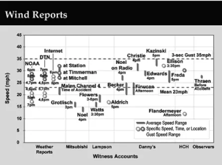
refusing to work at elevation under the prevailing weather. Following the accident, data collected by U.S. Weather Bureau (NOAA) stations, radio and TV reports, plus the recollections, estimates and guesses of numerous workers who testified, provided consensus wind conditions of 23 mph mean and 35 mph gust (3 s) speeds. Because the government sources for wind data were located at different regional airports (Mil-waukee and Racine), it was necessary to apply conversion factors for variations in terrain and elevation between the data collecting bases and the stadium. These calculations were accomplished in accord with ASCE Standard, ASCE 7-98., Minimum Design Loads for Buildings and Other Structures, Section C 6.0, Wind Loads. A plot showing the various indications of wind speed according to the numerous sources mentioned is presented inFig. 7.
8. The On-Site Investigation
Immediate post accident surveillance confirmed that the overturned crane upperworks (tub) had separated from the crawler base (carbody) and this upset produced traumatic failure of the king pin bottom end fixation assembly which allowed the king pin to withdraw from the carbody bore. The displaced upperworks (tub) and its rest position vis-a`-vis the carbody are featured inFig. 8. Significant reaction forces were developed during withdrawal of the 12-in. diameter king pin by bending resistance and bore contact friction. As a result, the king pin suffered permanent deformation in bending as seen inFig. 9. A plot of typical reaction forces imposed by the carbody bore on the king pin, engendered during overturn rotation, is presented inFig. 10.
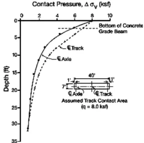
Also noted in the post accident inspection were ground deformations under the boom side (east) crawler track produced when it experienced full weight of the crane upperworks and suspended roof panel during overturn whilst the offside (west) track lifted from the ground. The average deformation was approximated by a 3/4 to 1 in. permanent (i.e., plastic) depression. Ground subsidence was exacerbated by side loads imposed on the boom-jib structure from wind gusts in turn augmented by the P-Delta effect of boom deflec-tion. These upsetting moments produced an unequal load distribution pattern and disrupted the normally con-stant ground pressure under the Transi-Lift. A plot of contact pressure decay with ground depth based on borings and soils test data is presented inFig. 11.
The combined sideward deflection of the boom and jib due to wind gusts, ground settlement, and the P-Delta effect produced destabilizing moments with respect to the three orthogonal coordinates; specifically, an east roll moment about longitudinal axis of the crawler base, a backwards pitch moment about an axis
perpendicular to the crawler tracks, and a counter clockwise yaw moment about the king pin axis or center of rotation.
8.1. laboratory investigation
Failed components of the king pin, bottom end fixation assembly are shown inFigs. 12–15. As seen, the bronze top hat bushing flange (Flange Parts) has fractured circumferentially around its inner periphery where the bushing is inserted into the carbody bore (Fig. 13). The flange also failed along radial fracture lines into three main pieces. Some incremental circular failed fragments are also recognized. The bronze spacer ring (Spacer Parts) has broken up along radial fracture lines into four sectors. These pieces demonstrate transverse bending with respect to the flat plane (Fig. 12). Also, the original rectangular cross section of the spacer was deformed into a trapezoidal shape with thinner thickness at the inner radius. The two bulky steel split ring retainer halves suffered bending and torsion distress, and a deep circular groove was impressed in the upper
Fig. 8. Overturned crane, tub separated from crawler base.
Fig. 10. Carbody bore forces on king pin during overturn rotation.
Fig. 11. Ground stress distribution below crawler track.
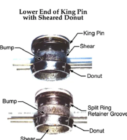
faces of both segments (Fig. 14). The lower faces are marked by sharp corner indentations from serious con-tact with the bottom end cap (donut) of the king pin. The donut itself has been pushed off the king pin under the immense axial forces which initiated circumferential failure in pure shear (Fig. 15).
Fig. 13. Top hat bushing failed pieces.
Fig. 14. Split ring retainer halves.
9. Wind loads
Very extensive and detailed studies, both analytical and experimental, were performed to obtain wind loads on the Lampson Transi-Lift, boom and jib structures as well as, and more importantly, wind loads on the 4R3 roof panel section trusses. A prodigious inventory of each and every structural member in the open lattice trusses for the boom, jib, jib strut, and mast of the Lampson Transi-Lift crane was identified and detailed as to geometry, shape, and location, etc.
A 200:1 model of the stadium and representative wire sections for the boom lattice structure and the roof trusses were constructed to scale. The wind tunnel model and hot wire anemometer taps mounted on the dummy boom are shown inFig. 16. Using the Mitsubishi engineering design drawings for reference, the fol-lowing factors were considered for the individual exposed members of the roof panel section trusses: width, length, frontal area, drag coefficient (CD), yaw correction factor, aspect ratio correction factor, median
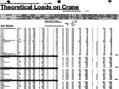
eleva-tion, dynamic pressure, drag force, unshielded moment, shielded area fraceleva-tion, shield coefficient, net force, and shielded moment. Sample pages from a large binder representative of the wind engineering calculations per-formed, are included asFigs. 17 and 18.
Fig. 16. Wind tunnel model of stadium with hot wire probes.
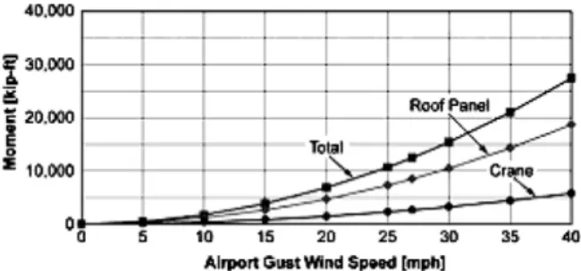
Results for the theoretical loads on the crane were: Total Area, 11,022 ft2, Drag Force 23,457 lb, and Moment 3368 ft-kip. Similar quantities for the 4R3 Roof Panel Section Trusses were: Total Area 10,825 ft2, Drag force 42,227 lb, and Moment 12,815 ft-kip. The quantity designated, Moment, refers to the destabilizing influence tending to overturn the crane upperworks and its suspended roof panel section with respect to the tub-carbody interface (7.53 ft above ground).
Mean wind velocity distributions for the crane placement vis-a`-vis the as built stadium configuration at time of accident, with representative surrounding terrain, were determined in the large subsonic 8 ft·8 ft wind tunnel. These measurements were used as correction factors to calibrate the theoretical wind loads. All of the wind engineering work was performed by Cermak Peterka Petersen, Inc. (CPP), Wind Engineering Consul-tants, Fort Collins, Colorado.
A plot of results obtained from the present investigation which correlates the crane overturning moment due to lateral wind loads versus airport gust wind speed is presented in Fig. 19.
10. Wind operations
The conventional dictates of crane operation under windy site conditions impose a 30 mph out-of-service velocity limit for the crane itself. That is, the crane must be shut down and the boom-jib lowered to ground under an in-extremis wind environment. For less severe job site conditions, even with 10 mph winds, it is usual craning practice, at very least, to consider moderating adjustments. More importantly, lifting capacities of a crane operating under 20 mph or more winds, especially when the loads are irregular with large cross section (sail area), must be derated both with respect to strength and stability.
Fig. 18. Sample data sheet and wind load calculation format.
The Lampson Transi-Lift was rated under boom strength and crane stability criteria for a 20 mph wind limit condition. However, this limit per SAE J1093 only applies to the crane and its appurtenant boom, jib and mast structures. By specific exclusion, the 20 mph limit does not acknowledge adverse contributions to stability that are produced by wind acting on the load. A summary of pertinent wind operation craning guide-lines is presented inTable 4.
11. Design analysis
Reference is made toFig. 20which is a schematic free body diagram of the tub, king pin and carbody where self weights, rated load (P), 2% side load and interactive forces are shown. The upward axial force,FT, on the Table 4
king pin required to displace (downward) and fail the bottom end cap (donut), based uniquely on shear frac-ture area and flow stress, (average of yield and ultimate strengths) is 5640 kip. On the other hand, and as noted previously,FTdemand on the king pin bottom fixation assembly at the 2% side load design condition would
be zero.
Another potential ‘‘failure’’ mode under extreme lateral (side) load is gross overturning of the entire crane system about the longitudinal axis of the front crawler base. The dead weight (gravity) resistance to gross overturning vis-a`-vis the carbody centerline provided by the 3770 kip upperworks (load, boom, jib, mast, etc.), 72.7 kip tub and 650 kip carbody, all acting vertically at the tub centerline is 67,390 ft-kip. At incipient overturn, the tension demand, FT, on the kingpin, found by summing moments about a contact point
(ful-crum) at the outer edge of the carbody thrust bearing, would be 5288 kip.
Thus, a most interesting conclusion drawn from these simple calculations is fact that the axial load required to cause king pin donut failure in pure shear of 5640 kip is greater than the load demand of 5288 kip on the king pin bottom end split ring retainer assembly to lift entire deadweight of the carbody itself.1Apropos, any argument that the king pin, bottom end fixation should have been changed back to a threaded nut (Mitsubishi allegation) as conceived in an initial Transi-Lift king pin design for a barge mounted unit is moot.
12. Structural and stability analyses
Structural calculations were carried out for the crane boom, jib and stinger lattice truss assemblies. Stability studies were also performed for the crane and suspended roof panel configuration (Fig. 21). The COSMOS/M finite element code by Structural Research and Analysis Corporation, Version 2.5, was used. Some of the most important results obtained are shown inFigs. 22–24.
Fig. 22, titled King Pin Axial Load versus Side Load due to wind, confirms that at the 2% design side load condition there would exist no axial forces on the king pin bottom fixation assembly. The king pin experiences initial load at about 2.5% side load. The bottom fixation assembly does not reach the yield (failure) criterion for the composite group of parts (i.e., 3990 lb) until 4.8% side load, that is, 2.4 times greater than the design, or allowable, 2% condition. The curve shown includes the destabilizing contribution of crane base rotation due to lateral ground displacement under the boom side (east) crawler track, and the additional overturning moment due to lateral deflection of the crane boom and jib (P-Delta).
Fig. 23, King Pin Axial Load Versus Side Load due to ground slope, confirms that under the 0.2% out-of-level design condition axial forces do not develop in the king pin until an equivalent 2.3% side load, a
1
It will be shown later that the axial load required to initiate failure of the bottom end assembly, as opposed to the donut per se, is 3990 lb. Apropos, king pin withdrawal occurs before gross overturn.
condition greater than the 2% design constraint. On the other hand, if an 0.8% out-of-level (2.9 in. per 30 ft) is assumed, based on calculations by one investigator (Lenzini) that the ground was disturbed to this degree at incipient overturn under both elastic and plastic displacements, than king pin failure would be predicted at 4% sideload, or twice the essential design criterion.
Fig. 22. King pin axial load vs. side load due to wind effects.
Fig. 23. King pin axial load vs. side load due to ground effects.
Fig. 24, Gust Speed Versus Out-of-Level, Interaction Curve, provides a means of correlating the compound criterion for crane overturn due to king pin bottom end failure with combinations of gust speed and/or out-of-level condition. The interaction curve incorporates both P-Delta and base rotation effects. The most likely fail-ure condition at time of accident is suggested for a 3.6 in., out-of-level orientation and 35 mph maximum gust. As comparison, the design condition for out-of-level (3/4 in. per 30 ft) would require a 40 mph gust speed for overturn. At an 11.5 mph mean wind speed,2the crane could sustain an egregious 13.5 in. per 30 ft out-of-level condition at incipient overturn.
Finally, representative finite element stress analyses were carried out for all of the king pin bottom end assembly components. A typical example is shown in Fig. 25. Here hoop stress distribution in the spacer due to axial compression and radial dilatation is portrayed for normal friction on the spacer top and bottom side faces between the top hat flange and split retainer ring halves. The tension band agrees with fact that the four radial fractures experienced by the spacer initiated at the outer periphery. All stress calculations were per-formed with the ANSYS finite element code, Version 5.6.
13. Metallurgical examination
The failed pieces were subject to standard metallurgical laboratory procedures. In particular, fractography, metallography, hardness traverses, tensile bar tests, Charpy impact tests and chemical analyses were per-formed. All results were unremarkable, no anomalies with respect to materials or fabrication processes were found. The top hat bushing material was identified as CDA-863, ASTM B22 manganese bronze, the spacer as CDA 932, ASTM B584 high lead tin bronze, the split retainer ring as A-514, GrE steel and the king pin as AISI 4340 H.T. steel at 100 ksi minimum yield.
All fractures were due to gross traumatic overload. As a corollary, no evidence of progressive (i.e., fatigue) or corrosion assisted failure was recognized.
14. Failure sequence
The sequence of king pin bottom end fixation component failures are portrayed in the artistic renderings of
Figs. 26–29.Fig. 26shows the assembly under load, prior to failure of any specific part. Due to the huge axial king pin withdrawal forces precipitated at incipient overturn, the split retainer halves are displaced upward
2
Howard Sharpiro, P.E., a noted crane operations consultant, established this wind speed as an upper practical and safe limit for the lift at issue.
against the carbody bore and experience sharp edge deformations, in compression, by the donut on their lower faces.
InFig. 27, the breakup of parts has begun. The 3/4 in. thick top hat bushing flange (119 ksi, ult.) has expe-rienced both radial and circumferential fractures in bending as a consequence of being forced up against the carbody bore. The first bang heard on the video undoubtedly relates to the radial fractures and the second bang, perhaps, to the circumferential fracture(s). The spacer (30-38 ksi, ult) has also split along radial fracture paths into four parts which could represent the third bang heard on the videotape. No surprise that two dia-metrically opposite fractures of the spacer were congruent with the split orientation of the retainer ring halves.
Fig. 26. King pin bottom end cap assembly, initial deformation pattern.
Fig. 27. King pin bottom end cap assembly, top hat flange and spacer fractures.
The spacer parts were ejected radially with considerable impulse since they were found next to the left and right crawler tracks, a launch distance of about 12 ft. It is probable that the dust cloud noted in the video was produced by the bushing flange parts and/or donut hitting the ground following forced downward ejection.
Fig. 28shows in detail the segmented portions of the top hat bushing flange inner periphery where circular fragments of the bushing flange broke away in downward bending after being impressed into top faces of the split ring retainers to produce the noted deep grooves (Fig. 29).
Finally,Fig. 29shows the final stage of failure where the donut has been sheared off lower end of the king pin.
15. The Litigation
The issues in contention during the ensuing litigation concerned two widely disparate theories of failure. The Mitsubishi experts insisted that addition of the 1/2 in. soft bronze spacer to the king pin bottom end fix-ation assembly was the root cause and origin of the overturning failure. Lampson and the present authors claimed that the sole and unique cause of the accident was operation during high winds with a load that man-ifested a vast sail area subjected to excessive drag forces, both steady state due to prevailing mean winds, and dynamic in response to gusts.
The spacer issue related to the Lampson Transi-Lift’s prior genealogy. Apropos, the crane was designed and built originally to be barge-mounted on a pedestal for a bridge project over the Severn River in the United Kingdom. Upon completion, the Transi-Lift crane was moved to Milwaukee for the stadium job. Here, the upperworks (tub) was fitted to a crawler base in lieu of the pedestal. In order to accommodate the new make up and provide axial tolerances for king pin adjustment it was necessary to introduce a bronze spacer to the assembly. The need for this modification is seen clearly inFigs. 30 and 31.
Fig. 30shows the king pin top end detail and the 290 lb nut used to suspend the king pin. As seen, with-out the spacer, a few threads of the nut remained disengaged from the king pin and, more importantly, only 1/4 in. of available free axial nut adjustment exists in the stack package. Fig. 31shows the same detail with the spacer included. Also, a thicker top end thrust bearing is used (1.19 in. vs. 0.75 in.). With these changes, full thread engagement of the nut results and the amount of free travel for axial adjustments is enlarged to 1–1/4 in. The spacer also provides tribological advantage at the bottom end where it isolates the hard steel (120 ksi, ult.) split ring retainer halves from direct contact with the embedded soft bronze top hat bushing flange.
The etiology of failure promoted by Mitsubishi claimed that under ‘‘moderate’’ wind induced side loads, the relatively weak bronze spacer fractured and the resultant ejection of the spacer pieces ‘‘as watermelon seeds (sic)’’ created a sudden dynamic jolt to the almost 2000 tons of upperworks and load which thereupon precipitated the overturn. Conversely, the present authors’ explanation for the accident was simply that the high side loads imposed on the crane boom, jib and roof section panel by the prevailing weather produced destabilizing boom deflection (P-delta) and ground depression (out-of-level) conditions which engendered
Fig. 30. King pin upper nut fixation detail, no spacer.
Fig. 31. King pin upper nut fixation detail, with spacer.
overturning moments well above and beyond the normal 2% design limit. Thereupon, the king pin bottom end assembly failed as the king pin was displaced upward due to axial withdrawal forces.
The analytical characterisation of these findings is presented inFig. 32. Here, the king pin axial load req-uisite to failure of the bottom end cap fixation assembly, not the donut per se, is presented for a variety of conditions. The most representative model is the load vs. extension plot for a spacer that experiences nominal frictional stresses on its upper and lower faces that resist dilation, breakup, and ejection of the failed parts. The peak load determined for this condition was about 3990 lb. The plots inFigs. 22 and 23show this force as a failure criterion under the designation, Yield.
16. Conclusions
The Miller Park accident, where a huge crane overturned while setting a ponderous roof panel section in place, was precipitated by a combination of adverse wind speeds and gusts coupled with an out-of-level run-way foundation and ground softness. The wind forces engendered sideward displacement of the roof panel with accompanying horizontal load and lateral displacement at the jib tip. The adverse lateral loading inten-sified bearing pressures at the rear corner of the load-side carbody crawler track which exacerbated ground subsidence and/or depression. The magnitude of side load surpassed the design limit for resistance to over-turning based solely on self weight. Consequently, an unfavorable bending moment was imposed on the king pin which was designed to serve uniquely as an unloaded locating means between the crane upperworks, or tub, and the crawler base, or carbody. Ultimately, the side loads which provoked incipient failure in the king pin, bottom end cap fixation assembly were almost 2–1/2 times greater than the requisite 2% design condition postulated in SAE J1093.
The decision to go forward with the roof panel lift under obvious conditions of high mean wind speed and gust duress was solely the responsibility of the general contractor, not the crane designer, owner and lessor. The SAE J1093 crane boom strength and stability standard indicates clearly that considerations of winds on loads are outside the realm of the crane design and rated capacity charts. In this context, the critical plan for a given heavy lift project must be addressed uniquely by those most familiar with the load itself and its behavior in suspension under severe wind conditions. Apropos, a dedicated engineering study of destabilizing wind forces acting on the roof panel should have been undertaken for the present lift. Unfortunately, this task was neither addressed nor accomplished.