Numerical Analysis of Mushroom-type Traveling Wave
Electro-absorption Modulators Using Full-Vectorial Finite Difference Method
K. Abedia, V. Ahmadia, E. Darabib, and M. K. Moravvej-Farshia
a Department of Electrical Engineering, Tarbiat Modares University, Tehran, Iran b Plasma Physics Research Center, Science and Research Campus, IAU, Tehran, Iran
E-mail: [email protected]
Abstract— Larger width of P-cladding layer in p-i-n waveguide of traveling wave electro-absorption modulator (TWEAM) results in lower resistance and microwave propagation loss which provides an enhanced high speed electro-optical response. In this paper, a full-vectorial finite-difference-based optical mode solver is presented to analyze mushroom-type TWEAM for the first time. In this analysis, the discontinuities of the normal components of the electric field across abrupt dielectric interfaces which are known as the limitations of scalar and semivectorial approximation methods are considered. The optical field distributions in mushroom-type TWEAM and conventional ridge-type TWEAM of the same active region for 1.55 μm operation are presented. The important parameters in the high-frequency TWEAM design such as optical effective index which defines optical velocity and transverse mode confinement factor are calculated. The modulation response of mushroom-type TWEAM is calculated by considering interaction of microwave and optical fields in waveguide and compared to that of conventional ridge-type TWEAM. The calculated 3dB bandwidths for ridge-type and mushroom-type TWEAM are about 139 GHz and 166 GHz for 200 μm and 114 GHz and 126 GHz for 300 μm waveguide length, respectively.
KEWORDS: Full-vectorial finite difference method (FV-FDM), Traveling wave modulator, Electro-absorption, Mushroom-type TWEAM.
I. INTRODUCTION
High-speed and high-efficiency electro-absorption modulators (EAM) are key devices for microwave analog fiber links as well as high-data-rate optical wavelength division
multiplexing systems and high-speed optical time division multiplexing systems. Broad-band and high-electrical-to-optical efficiency are two main criteria in the design of EAM. Toward the high performance in the EAM application, traveling-wave (TW) structure is one of candidates to overcome the conventional RC-lump limitation. Therefore, the waveguide can be made long to enhance the extinction ratio and high modulation efficiency without losing its high-speed performance [1-5]. However, in practical, the limitation of TWEAM in p-i-n layers is generally restricted by the high microwave propagation loss because of the metal skin effect, highly-loaded capacitance and the high resistance in p-layer [6]. Increasing the width of p-cladding layer with the same i-layer for reduction of the p-i-n waveguide resistance can improve the microwave propagation loss and thus the high-speed electro-optical response [7].
The optical waveguide defines the intrinsic cross-sectional geometry of the TWEAM. The waveguide core region is the absorption region of the modulator, which from the electrical point of view presents the depletion layer of a hetero-junction pin-structure. Therefore, electrical, optical, and electro-optical designs are interlocked. The optical wave is guided by the index guiding layers formed by the active layer (absorption region) together with upper and lower cladding layers. The thickness of the active layer determines the electric field strength for a given applied voltage. The value of the field dependent absorption coefficient inside this material is subject to its bandgap compared to the photon energy
[8].
The optical effective index defines the optical velocity, which is an important parameter in the high-frequency TWEAM design. Transverse mode confinement factor is also very important since only the confined fraction of the optical mode within the active region can be modulated.
Accurate calculation of modal fields, optical effective index and confinement factor for optical waveguide of TWEAM is perhaps the most basic and indispensable for designing TWEAM. Various numerical techniques, e.g., finite difference method (FDM) [9, 10], finite element method (FEM) [11], imaginary distance beam propagation method (ID-BPM) [12], and mapped Galerkin method (MGM) [13], have been proposed to perform this task. Among them, the FDM is an attractive candidate because of the simplicity of its implementation and the sparsity of its resulting matrix.
The early application of the FDM was based on the scalar wave equation which is valid only for the optical waveguides with very small refractive index difference (weakly guiding approximation). In recent years, the FDM has been employed to determine semivectorial guided modes where the polarization dependence is taken into account [14]. Yet the polarization coupling is ignored. More recently, the FDM has been applied for analyzing the full vectorial modes for the optical waveguides with large refractive index differences in regions of high field intensity [15].
In this paper, a full-vectorial finite-difference-based optical mode solver is used to analyze mushroom-type traveling wave electro-absorption modulator for the first time. The discontinuities are considered in FDM, and full-vectorial distributions of the modal fields can be generated for mushroom-type and ridge-type traveling wave electro-absorption modulators. Three adjacent grid points are used to approximate each differential operator, so the solution is more accurate than that obtained by using two adjacent grid points. The optical effective index and transverse mode confinement factor for mushroom-type and
ridge-type TWEAMs are calculated and compared. Then, the modulation response of mushroom-type TWEAM is calculated by considering interaction between microwave and optical fields in waveguide and compared with conventional ridge-type TWEAM.
II. THEORY AND ANALYSIS
A. Full-vectorial Wave Equation
The full-vector eigenvalue equation based on electric fields can be derived from the Maxwell’s equations. In a source free region, and assuming a periodic time variation, ejωt, we have:
0
jkη
∇× = −E H , 2
0
1
jk n
η
∇× =H E (1)
( )
n2 0∇ ⋅ E = , ∇⋅ =H 0 (2)
where E and H are the electric and magnetic field vectors, k and η0 are the free-space wave vector and wave impedance, respectively.
n=n(x,y) is the refractive index of the guiding medium. Through a simple derivation [16], we have the following full-vectorial wave equation for the electric field:
( )
1
2 2 2 2 0
2 n n k
n
∇ + ∇⎛⎜ ∇ ⋅ ⎞⎟+ =
⎝ ⎠
E E E (3)
Only two components of the electric field are required. If the transverse components exand ey
are known, the longitudinal component may be calculated by:
( )
n2 0∇ ⋅ E = (4)
for the case that refractive index profile of an optical waveguide does not vary along the propagation direction. Therefore, it makes sense to separate the electric field into transverse and longitudinal components, and assume z-dependence of e−jβz.
(
x y z, ,)
=(
+ˆez)
e−j zβE et z (5)
where β=k0no_eff is the propagation constant and no_eff is the effective index. The full-vector wave equation can be written in terms of the transverse components,
( )
1
2 2 2 2 2
2 n n k
n β
∇ + ∇⎛⎜ ∇ ⋅ ⎞⎟+ =
⎝ ⎠
et et et et (6)
The longitudinal component ez can be computed from etusing the divergence relation:
( )
1 2
. 2
j ez n
n
β = ∇et + ∇ ⋅et (7)
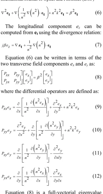
Equation (6) can be written in terms of the two transverse field components exand ey as:
2
Pxx Pxy ex ex
e e
Pyx Pyy y =β y
⎡ ⎤ ⎡ ⎤ ⎡ ⎤
⎢ ⎥ ⎢ ⎥⎣ ⎦ ⎢ ⎥⎣ ⎦
⎣ ⎦ (8)
where the differential operators are defined as:
( )
2 21 2 2
2 2
n ex ex
P exx x n k ex
x n x y
∂ ∂ ∂ = + + ∂ ∂ ∂ ⎡ ⎤ ⎢ ⎥ ⎢ ⎥ ⎣ ⎦ (9)
( )
2 21 2 2
2 2
n e
ey y
P eyy y n k ey
y y x n ∂ ∂ ∂ = + + ∂ ∂ ∂ ⎡ ⎤ ⎢ ⎥ ⎢ ⎥ ⎣ ⎦ (10)
( )
2 2 12
n ey ey P exy y
x n y x y
∂ ∂ ∂ = − ∂ ∂ ∂ ∂ ⎡ ⎤ ⎢ ⎥ ⎢ ⎥ ⎣ ⎦ (11)
( )
2 2 12
n ex ex
P eyx x
y n x y x
∂ ∂ ∂ = − ∂ ∂ ∂ ∂ ⎡ ⎤ ⎢ ⎥ ⎢ ⎥ ⎣ ⎦ (12)
Equation (8) is a full-vectorial eigenvalue equation which describes the modes of propagation for an optical waveguide. The two coupled transverse field components ex and ey
taken together are the eigen functions, and the corresponding eigenvalue is β2. The non-zero diagonal terms Pxy and Pyx reveal that the two field components ex and eyare coupled, that is,
the eigenvalue equation cannot be divided into two independent eigenvalue equations to be solved separately for exand ey. Because of this
coupling, the eigen modes of an optical waveguide are usually not purely TE or TM in nature. Nevertheless, often one of the two transverse field components is much larger than the other, and the mode can be treated as quasi TE or TM.
B. OPTICAL WAVEGUIDE STRUCTURE FOR
TWEAM AND FINITE DIFFERENCE SCHEME
The p-i(MQW)-n structure of the mushroom-type electro-absorption waveguide modulator
is shown schematically in Fig. 1. The optical waveguide is described by a refractive index profile n(x,y). The refractive index profile has been broken up into small rectangular elements or pixels, of size Δx×Δy. Over each of these elements, the refractive index is constant. Thus, discontinuities in the refractive index profile occur only at the boundaries between adjacent pixels. Because the index profile is symmetric about the y-axis, only half of the waveguide needs to be included in the computational domain.
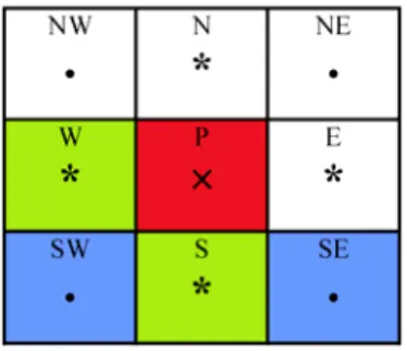
The finite-difference grid points, i.e., the discrete points at which the fields are sampled, are located at the center of each cell. The general situation for an arbitrary grid point P with its neighboring points N, S, W, E, NW, NE, SW, and SE is illustrated in Fig. 2. The refractive indices for these points are labeled here as nP, nN, nS, nW, nE, nNW, nNE, nSW, and
nSE, respectively.
Now we convert the partial differential Eq. (8) into a corresponding finite difference equation. We first deal with the differential operator Pxy which operates on ex. Because ex is continuous across horizontal interfaces, the ∂2ex/∂y2 term may be approximated with the simple three point difference, that is,
( )
(
)
2 1 2 2 2 Pex N P S
ex ex ex
y y
∂
≈ − +
∂ Δ (13)
Fig. 1 Schematic structure of mushroom traveling-wave electro-absorption modulator.
However, when there is an index discontinuity between W and P or between P and E, the finite difference equations must be
modified to account for the discontinuity in ex. One of the most straightforward techniques for deriving finite difference approximations is the Lagrange interpolation.
Fig. 2 Labeling scheme used for the finite difference model.
The Lagrange interpolation is simply the lowest order polynomial which goes through all of the sample points. The derivatives can then be easily computed from the polynomial coefficients of the interpolating function.
To accomplish this, we use a modified interpolation procedure in which we fit the points exW, exP and exE with a piecewise quadratic polynomial function (ex) as:
( )
2 in cell W 2 in cell P 2 in cell E
AW Bx Cx
x AP Bx Cx
AE Bx Cx
φ + + = + + + + ⎧ ⎪⎪ ⎨ ⎪ ⎪⎩ (14)
The function φ
( )
x is satisfied with the following conditions:( )
( )
2
2
exW AW B x C x exP AP
exE AE B x C x
= − Δ + Δ
=
= + Δ + Δ
(15)
Considering that n2e
x to be continuous at x= ± Δx/2, that
is,
( )
{
}
{
( )}
( )
{
}
{
( )}
1 1 2 1 1 2
2 2
2 4 2 4
1 1 2 1 1 2
2 2
2 4 2 4
nW AW B x C x nP AP B x C x
nP AP B x C x nE AE B x C x
− Δ + Δ = − Δ + Δ
− Δ + Δ = − Δ + Δ
(16) Equations (15) and (16) together give five linear equations which can be solved for the five unknown polynomial coefficients. After summarizing the results, we have
( )
(
)
( )
(
)
1
2 2
1 2 2
2 2
W P E
P exx xP Wex Pex Eex x
N P S
ex ex ex k nP P y
α α α
= − + +
Δ
− + +
Δ
(17)
where the constant αW, αP and αE are dimensionless
ratios defined by:
(
)
(
)
(
)
2 2 2 2
4
4 2 2 2 2 2 2
2 2 3
4 2 2 2 2
2 2
4 2 2 2 2 2 2
2 2 3
2 2 2 2
4
E 4 2 2 2 2 2 2
2 2 3
n nW P n nE W W
nP n nE P n nW P n nE W nP n nW P n nE P P
nP n nE P n nW P n nE W n nE P n nE W nP n nE P n nW P n nE W
α α α + ≡ + + + + + ≡ + + + + ≡ + + + (18)
A similar procedure can also be used to derive the finite difference equations for pyyey,
pxyey and pyxex. Then (7) is converted into a standard matrix eigenvalue equation.
This developed finite difference approximation can be applied even in the presence of abrupt dielectric interfaces where the field is discontinuous. The technique described here involves fitting a piecewise-quadratic polynomial to three adjacent grid points.
III. TWEAMFREQUENCY RESPONSE TWEAMs are devices to modulate light waves corresponding to traveling electric fields along the electrode consisting of a transmission line. Because the absorption coefficient of TWEAMs depends on the electric voltage, the modulation of optical wave occurs by the absorption change due to modulated electric signals. Fig. 3 shows the principle of operation and circuit model for a unit length of TWEAM transmission line [17, 3].
The circuit model contains the conduction resistance Rcon, the inductance Lm, the vertical series resistance RS, the junction capacitance
Cm, an outer parasitic capacitance Co, and a differential resistance Ro parallel to Cm which is caused by photo-generation of carriers in the intrinsic layer. The effect of junction resistance
Ro becomes significant only at high incident optical power.
The small signal frequency response for TWEAM can be obtained as follows [4,3]:
( )
0
2 1 _ 2
1
j n i l n c o eff
Pac V ei l
i
ω − Δ
∑
= Δ
=
⎛ ⎞
⎜ ⎟
⎜ ⎟
⎝ ⎠ (19)
where Vi is the modulating voltage in i section. The calculation of the small signal modulation response requires the knowledge of the optical index no_eff and the circuit model elements for calculation of Vi. The circuit elements can easily be extracted from the TWEAM transmission line microwave properties Z0 (characteristic impedance) and γ (propagation constant) [18], which are obtained via full-wave simulations of the given geometry.
(a)
' ' i i
V , Z ' '
n n V , Z
i
V
L
Z
O
C
m
C O
R
S
R m
L
con
R
S
Z
(b)
Fig. 3 (a) Principle of operation, and (b) circuit model for a unit length of TWEAM transmission line.
IV. RESULTS AND DISCUSSIONS
In this section, we use the full-vectorial finite difference optical mode solver to calculate the fundamental effective index and transverse mode confinement factor of a mushroom-type and traveling wave electro-absorption modulator.
The main material parameters in order to perform waveguide simulations are the refractive indices. The waveguide simulation considers 2-dimensional structures. The active region with thickness hiis composed of MQW.
The thickness of the active layer is considered to be 0.2 μm. In order to improve the junction capacitance, we use a small intrinsic buffer layer on top of the active layer with thickness of 0.2 μm [4]. The width of the active layer (Wa) is taken as 2 μm and simulation is carried out for the wavelength of 1.55 μm.
(a)
(b)
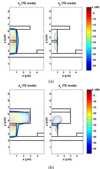
Fig. 4 Transverse electric field components ex and ey
for the fundamental quasi TE mode (a) ridge-type TWEAM, (b) mushroom-ridge-type TWEAM. Figure 4 depicts the waveguides cross-section and the calculated TE field contour of ridge-type and mushroom-type waveguides for
ex and ey. As mentioned before, the ex transverse field component is much larger than the ey component and the mode is treated as
quasi TE.
The effective index defines the optical speed, which should be known in the design of a traveling wave modulator. After computing modal eigenvalue β2 of traveling wave electro-absorption modulator, by solving (6), the effective index can be calculated as follows.
0 _
no eff = kβ (20)
Figure 5 shows the calculated effective index of mushroom-type and ridge-type structures for fundamental mode of TE polarization.
Fig. 5 Optical effective index for fundamental mode vs. active region thickness.
Figure 6 shows the optical confinement factor as a function of the active region thickness. 0.2 μm of MQW thickness yields an optical confinement factor of %19.1 for mushroom-type and %21.6 for ridge-type TWEAM. This is due to better confinement of the electric field in the intrinsic region of ridge-type compared to that of mushroom-ridge-type.
Fig. 6 Optical confinement factor vs. active region thickness
Typical values for the active region thickness are 0.2 to 0.5 μm [5].
Figure 7 shows the calculated microwave loss for mushroom-type and ridge-type TWEAM using finite element method. As the p-cladding layer width increases, the microwave loss decreases.
Fig. 7 Microwave loss vs. frequency.
The variation of microwave loss vs. P-layer width is illustrated in Fig. 8. In this analysis, the microwave frequency is assumed to be 80 GHz. As shown in the figure, increasing P-layer width leads to decrease microwave loss. As the P-layer width is increased the junction capacitance Cm increases because of the higher parasitic capacitance as shown in Fig. 9.
Fig. 8 Microwave loss vs. p-layer width.
Fig. 9 Junction capacitance vs. frequency. Figures 10 and 11 show the real parts of the characteristic impedance and microwave refractive index. As the p-cladding layer width increases, the microwave velocity and characteristic impedance of waveguide decrease due to increased junction capacitance in waveguide.
Fig. 10 Real part of characteristic impedance vs. frequency.
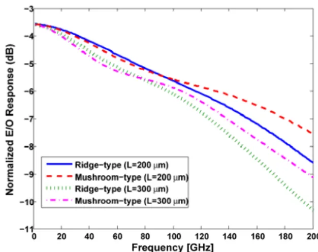
Figure 12 shows the calculated frequency response for mushroom-type and ridge-type TWEAM with different lengths and ZL=25 Ω. In this case, all the waveguide parameters are the same. The overall waveguide loss and velocity mismatch increase as the device length increases. The microwave loss and velocity mismatch reflect the decrease in optical modulation, as shown in the plot. The 3dB bandwidths for ridge-type and mushroom-type TWEAM are about 139 GHz and 166 GHz for 200 μm and 114 GHz and 126 GHz for 300 μm waveguide length, respectively.
Fig. 11 Microwave refractive index vs. frequency. Higher electro-optical response and speed indicates that better performance of mushroom-type is mainly due to the lower microwave loss.
Fig. 12 Frequency response for ridge-type and mushroom-type TWEAM with different waveguide lengths.
V. CONCLUSION
We have presented a full-vectorial finite-difference-based optical mode solver to analyze mushroom-type travelling wave electro-absorption modulator. Here, the discontinuities of the normal components of the electric field across abrupt dielectric interfaces have been considered in contrast to the scalar and semivectorial approximation methods. The important parameters in the high-frequency TWEAM design such as optical effective index which defines optical velocity and transverse mode confinement factor were calculated. The modulation response of mushroom-type TWEAM was calculated by
considering interaction between microwave and optical fields in waveguide and compared with conventional ridge-type TWEAM. Numerical values showed higher bandwidth for the mushroom-type TWEAM compared to the ridge-type of the same active region. The calculated 3dB bandwidths for ridge-type and mushroom-type TWEAM are about 139 GHz and 166 GHz for 200 μm and 114 GHz and 126 GHz for 300 μm waveguide length, respectively.
ACKNOWLEDGMENT
This work was supported in part by Iran Telecommunication Research Center (ITRC) under the Grant T-500-2984.
REFERENCES
[1] K. Kawano, M. Kohtoku, M. Ueki, T. Ito, S. Kondoh, Y. Noguchi, and Y. Hasumi, “Polarization-insensitive traveling-wave electrode electro-absorption (TW-EA) modulator with bandwidth over 50 GHz and driving voltage less than 2 V,” Electron. Lett., Vol. 33, pp. 1580– 1581,1997.
[2] S. Z. Zhang,Y. J. Chiu, P. Abraham, and J. E. Bowers, “25 GHz polarization-insensitive electro-absorption modulators with traveling-wave electrodes,” IEEE Photon. Technol. Lett., Vol. 11, pp. 191– 193, 1999.
[3] G. L. Li, S. K. Sun, S. A. Pappert, W. X. Chen, and P. K. L. Yu, “Ultrahigh-Speed Traveling-Wave Electro-absorption Modulator Design and Analysis,” IEEE
Trans. Microw. Theory Tech., Vol. MTT- 47, pp. 1177-1183, 1999.
[4] S. Irmscher, R. Lewén, and U. Eriksson, “Microwave properties of ultra high speed
traveling-wave electro-absorption modulators for 1.55 µm,” Proc. Integrated
Photonics Research (IPR’01), Monterey, California, Paper IME2-1, 2001.
[5] R. Lewén, S. Irmscher, and U. Eriksson, “Microwave CAD circuit modeling of a
traveling-wave electro-absorption modulator,” IEEE Trans. Microw. Theory
Tech., Vol. 51, pp. 1117–1128, 2003.
[6] K. S. Giboney, M. J. W. Rodwell, and J. E. Bowers, “Traveling-wave photodetector design and measurements,”
IEEE J. Sel. Top. Quantum Electron. , Vol. 2, pp. 622-629, 1996.
[7] Y. J. Chiu, T. H. Wu, W. C. Cheng, F.J. Lin, and J.E. Bowers, “Enhanced performance in traveling-wave electro-absorption Modulators based on undercut-etching the active-region,” IEEE Photon. Technol. Lett., Vol. 17, pp. 2065-2067, 2005.
[8] J. Piprek, Yi-Jen Chiu, and J. E. Bowers, “Analysis of Multi-Quantum Well Electroabsorption Modulators,” SPIE Proc. 4646-77, Physics and Simulation of Optoelectronic Devices X, Photonics West, San Jose, CA, 2002.
[9] Y. C. Chiang, Y. P. Chiou, and H. C. Chang, “Improved full-vectorial finite-difference mode solver for optical waveguides with step-index profiles,” J. Lightwave Technol., Vol. 20, pp. 1609-1618, 2002.
[10]J. Xiao and X. Sun, “A Modified full-vectorial finite-difference beam propagation method based on H-fields for optical waveguides with step-index profiles,” Opt. Commun., Vol. 266, pp. 505-511, 2006.
[11]S. S. A. Obayya, “Novel finite element analysis of optical waveguide discontinuity problems,” J. Lightwave Technol., Vol. 22, pp. 1420-1425, 2004.
[12]S. Jungling, and J. C. Chen, “A study and optimization of eigen mode calculations using the imaginary-distance beam-propagation method,” IEEE J. Quantum Electron., Vol. 30, pp. 2098-2105, 1994.
[13]J. Xiao and X. Sun, and M. Zhang, “Vectorial analysis of optical waveguides by the mapped Galerkin method based on
E fields,“ J. Opt. Soc. Am., Vol. B21, pp. 798-805, 2004.
[14]C. Vassallo, “Improvement of finite difference methods for step-index optical waveguides,” IEE Proc. J., Vol. 139, pp. 137-142, 1992.
[15]S. Sujecki, T. M. Benson, P. Sewell, and P. C. Kendall, “Novel vectorial analysis of optical waveguides,” IEEE J. Lightwave Technol., Vol. 16, pp. 1329-1335, 1998.
[16]R. Scarmozzino, A. Gopinath, R. Pregla, and S. Helfert, “Numerical Techniques for Modeling Guided-Wave Photonic Devices,” IEEE J. Select. Topics Quantum Electron., Vol. 6, pp. 150-162, 2000.
[17]Y.-J. Chiu, S. Z. Zhang, V. Kaman, J. Piprek, and J. E. Bowers, “High-Speed
Traveling-Wave Electroabsorption
Modulators,” Symposium on Radio Frequency Photonic Devices and Systems II, 46th SPIE Annual Meeting, San Diego, CA, 2001.
[18]S. Irmscher, R. Lewén, and U. Eriksson, “Influence of Electrode Width on High Speed Performance of Traveling-wave Electro-absorption Modulators,” Proc. Indium Phosphide and Related Materials (IPRM’01), Nara, Japan, Paper WA3-3, 2001.