Acknowiedgements
I would like to thank Dr. Singer for his patient guidance and assistance during the course of this research project. I would also like to thank Dr. Michael Aitken and Dr. Donald Francisco for being on my review committee.
I would like to thank Jim Nix and Michael Hacker for their roles in the laboratory and field testing that was performed during this research.
This research project was funded by EIMCO Process Equipment
Manufacturing Company and the consulting firm of Camp Dresser & McKee. Technical assistance was also provided by Chris Schuiz of CDM and Hollie
Chapterl INTRODUCTION...1
Chapter 2 Background and Theory...5
Brief History...5
Theory of Coagulation...5
Background...5
Coagulants...6
Polymers...7
Theory of Flocculation...9
Background...9
Mechanical FlocculationA/elocity Gradients...9
Floe Volume Concentration...13
Hydraulic Flocculation...15
Sludge Blanket Clarifiers...16
Performance Evaluation...17
Pilot Plant Studies...18
Objectives...18
Scale Effects...19
Chapters Experimental Procedures...21
Design of Pilot Plant...21
Media Selection and Tank Configuration...25
Field-Test Locations...27
Flocculation Test Procedures...29
Chapter 4 Results and Discussion...33
Introduction...33
Results...33
OWASA Testing...33
Durham Testing...37
Discussion of Results...44
Coagulant Chemistry/Source Water Quality...44
Polymer Addition...48
Media Selection, Stratification, and Bed Depth...50
Bed Configuration...52
Water Temperature...58
Loading Rates...59
Reproducibility...63
Engineering Implications...68
Chapter 5 Conclusions and Recommendations...70
Conclusions of Study...70
Recommendations...71
References...73
page no.
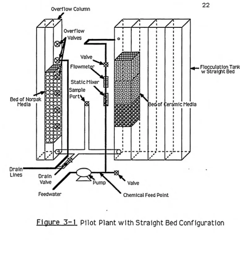
Figure 3-1 Pilot Plant with Straight Bed Configuration 22
Figure 3-2 Pilot Plant with Tapered Bed Configuration 23
Figure 4-1 The Effect of Coagulant Addition and Source Water 45
Quality on Head Loss Accumulation
Figure 4-2 The Effect of Coagulant Addition and Source Water 45
Quality on Fiocculator Effluent Turbidity
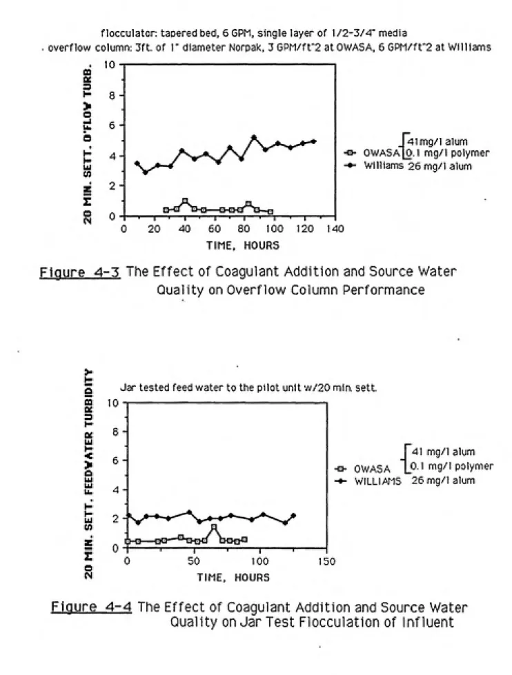
Figure 4-3 The Effect of Coagulant Addition and Source Water 46
Quality on Overflow Column Performance
Figure 4-4 The Effect of Coagulant Addition and Source Water 46
Quality on Influent Jar Test Performance
Figure 4-5 The Effect of Polymer Addition on Head Loss Accumulation 49 in Pilot Plant Tests at the Williams Plant
Figure 4-6 The Effect of Polymer Addition on BCM Fiocculator 49
Performance at the Williams Plant
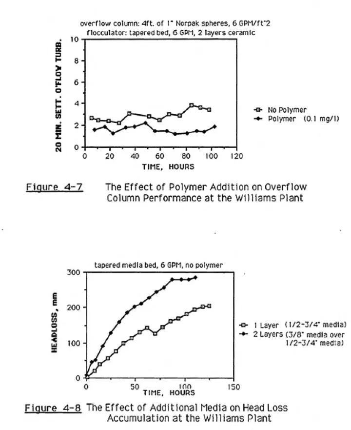
Figure 4-7 The Effect of Polymer Addition on Overflow Column SI
Performance at the Williams Plant
Figure 4-8 The Effect of Additional Media on Head Loss Accumulation 51
at the Williams Plant
Figure 4-9 The Effect of Additional Media on Fiocculator Performance 53
at the Williams Plant
Figure 4-10 The Effect of Additional Media on Overflow Column 53 Performance at the Williams Plant
Figure 4-11 The Effect of Additional Media on Head Loss 54 Accumulation at the OWASA Plant
Figure 4-12 The Effect of Additional Media on Fiocculator 54 Performance at the OWASA Plant
Figure 4-13 The Effect of Additional Media in Fiocculator on 56
Overflow Column Performance at the OWASA Plant
Figure 4-14 The Effect of Bed Configuration on Fiocculator Head Loss 56
Figure 4-16 The Effect of Bed Configuration on Overflow Column 57 Turbidity at the Williams Plant
Figure 4-17 The Effect of Temperature on Treatability of Pilot Plant 60 Influent at the Williams Plant
Figure 4-18 The Effect of Flow Rate on Head Loss Accumulation 60
at the Williams Plant
Figure 4-19 The Effect of Flow Rate on Effluent Turbidity from the 61
BCM Flocculator at the Williams Plant
Figure 4-20 The Effect of Flocculator Loading Rate on Overflow 61 Column Turbidity at the Williams Plant
Figure 4-21 The Effect of Flow Rate on Head Loss Accumulation 62
at the OWASA Plant
Figure 4-22 The Effect of Flow Rate on Effluent Turbidity from the 62
BCM Flocculator at the OWASA Plant
Figure 4-23 Consistency of Flocculator Effluent During Stress- 64
Testing of Overflow Column at the Williams Plant
Figure 4-24 The Effect of Loading Rate on Overflow Column 64
Effluent at the Williams Plant
Figure 4-25 The Effect of Loading Rate on Overflow Column 66
Performance at the OWASA Plant
Figure 4-26 Head Loss Accumulation During Sequential Identical 66
Tests at the OWASA Plant
Figure 4-27 Flocculator Effluent Turbidity Dunng Sequential 67
Table 4-1 Summary of Results of OWASA Field Tests with 34
Tapered Bed Configuration
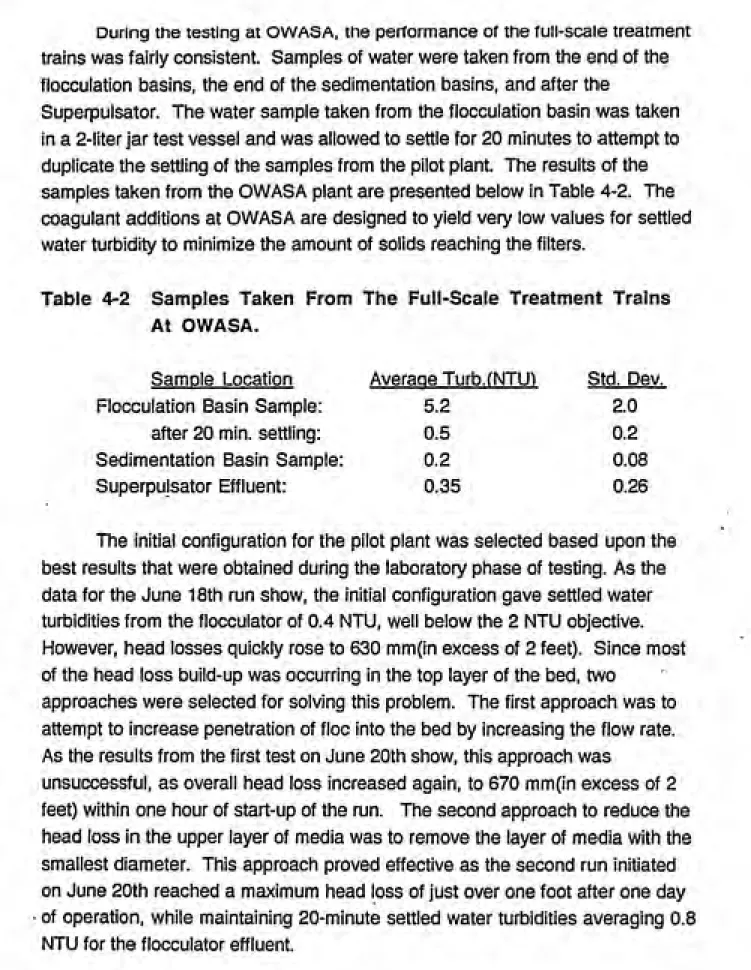
Table 4-2 Samples Taken from the Full Scale Treatment Trains 35
at OWASA
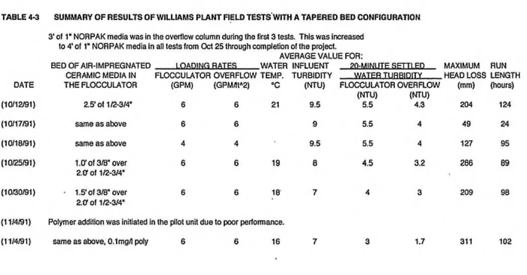
Table 4-3 Summary of Results of Williams Plant Field Tests with a 38
Tapered Bed Configuration
Table 4-4 Samples Taken from the Full Scale Treatment Trains 39
at Williams
Table 4-5 Effect of Polymer Dose on Settled Water Turbidity for 40
Durham Jar Tests
Table 4-6 Summary of Results of Williams Plant Field Tests with a 42
The roots of this research stem from the theories of hydraulic flocculation developed by Smoluchowski in the early portion of the twentieth century as well as later research by Camp and Stein in the 1940's. Their work was aimed at better understanding the principles involved during the flocculation stage of drinking water treatment. The combination of coagulation and flocculation followed by sedimentation, filtration and disinfection have been the norm in the treatment of drinking water since the 1920's. While this project was focused on improving the flocculation step of the drinking water treatment process, it is important to note that changes in any stage of treatment affect every subsequent stage. This report will attempt to keep that notion in mind and not lose sight of the larger picture which is overall treatment and finished water quality.
Flocculation is the process of causing small particles to aggregate into larger ones through particle collisions. These larger particles can then be settled or filtered out of the water. Included in these particles that are removed are many of the pathogenic organisms in the raw water along with many of the organic precursors to the formation of disinfection byproducts. Flocculation is therefore a critical step in insuring the safety of the water we drink. Also, in recent years, the overall quality of drinking water produced in the United States has increased to a point where the public has come to expect water of the highest quality available. Thus the success of any new technology will not only be measured by its ability to meet the standards of the Safe Drinking Water Act
but also the personal standards set by the consumer.
The flocculation technology that was investigated in this research is a recently patented process termed buoyant coarse media(BCM) flocculation. Buoyant coarse media flocculation operates on the same basic physical principles as gravel bed flocculators that have been used in many Third World countries. The media bed used in these types of hydraulic flocculation
processes acts similar to a coarse filter bed. In buoyant coarse media
flocculation, the water is passed through a bed of buoyant media that is several feet deep. There is a head loss or a loss of energy that is associated with passing the water through the bed. This head loss is due to fluid shear as the
is believed to be superior to traditional mechanical flocculation with respect to the hydraulic residence time required for effective flocculation to occur. It also
has the advantage of eliminating equipment and moving parts that are common
to mechanical flocculation and are susceptible to mechanical failure while in
use.
The key feature of the buoyant coarse media flocculator as opposed to a
gravel bed flocculator is the buoyancy of the media bed. This makes cleaning the bed much easier. Traditional gravel bed flocculators must be excavated and cleaned or replaced to remove material that becomes trapped within the bed. This is a very costly and time-consuming process and it is one of the greatest drawbacks of media bed flocculators that have been tested to date. The buoyant media bed can be expanded in place by air-scouring and/or increasing the flow rate through the bed. This will remove particles which have become trapped in the bed, analogous to the backwashing of filters. By
regularly cleaning the bed to remove trapped particles, it is possible to prevent excessive head loss from building up within the media bed. This is a crucial point as the amount of head available in a conventional water treatment plant is typically a limiting factor. Increasing the available head increases power costs associated with pumping if this option is even possible at a given treatment
plant.
The research in this project deals with many aspects of buoyant coarse media flocculation. This was a pilot-scale study performed to determine the optimal type of media, sizes of media and media bed depths, as well as the best
flow rates for operating a buoyant coarse media flocculator. The effectiveness of the process under various operating conditions was evaluated on the basis of
effluent turbidity and head loss buildup. The experimental work was performed using a pilot-scale flocculation unit capable of being moved to different sites. The testing performed consisted of two distinct phases, a laboratory study and a
field study.
The laboratory portion of the research was conducted first. During this stage, the pilot plant was operated on a simulated raw water dosed with a
tapered media bed to help taper the velocity gradients was investigated. One of
the goals of this stage of testing was to determine an optimal, or at leastacceptable, configuration of the pilot-scale unit for testing on natural waters.
Many standard jar tests were performed during this phase of testing. They were
conducted to ensure that proper coagulant doses were added to the raw water
and to determine the effect of varying the coagulant dose. A detailed
description of this work is contained in another University of North Carolina Masters report entitled A Laboratory Studv of Buoyant Coarse Media
Flocculation. written by James Nix (1992).
The field studies which followed the laboratory studies consisted of
transporting the pilot plant to two local water treatment plants: the Orange Water
And Sewer Authority (OWASA) Water Treatment Plant on Jones Ferry Road in
Carrboro, North Carolina and the Williams Water Treatment plant located in Durham, North Carolina. The pilot plant was operated on coagulated/rapid-mixed water at each of these plants and its performance was compared to the performance of the full-scale flocculation processes. The pilot plant utilized therapid mix of the full-scale plant by drawing effluent from the full-scale rapid-mix
basin. Several different media beds were tested at each location, and each bed
was run at various loading rates to evaluate the pilot-plant performance under
varying levels of stress.
Buoyant coarse media flocculation is desirable for a number of reasons,
the most significant being very short hydraulic detention times for the
Brief History
Coagulation and flocculation processes were not well understood before the 1920's and some aspects of these processes still are not fully understood.
In the 1890's, several cities began experimenting with rapid sand filtration
which required the addition of a coagulant to enable the relatively coarse sand
to remove fine particles from the water. During these early years, the coagulant was added to the water in the settling basin, which was typically located directlyahead of the filters to remove any large solids from the water. This basin was
then referred to as a coagulation basin and, although it was not mechanically
mixed, it was observed that some flocculation was occurring in the basin. One
of the first mixing basins to be installed before sedimentation was built atJackson, Mississippi, in ISM."! By the early 1920's, the addition of flocculation
or mixing basins before sedimentation was common in almost every new facility because they improved sedimentation and increased the length of filter runs.
Theory of Coagulation
Background
The mechanism of aggregating colloidal particles into particles large
enough to settle involves two distinct processes. The particles must be brought
into contact with each other using some form of transport, and the particles must
first be destabilized to allow attachment when interparticle contact does occur.The addition of chemicals to the water to destabilize the particles occurs during
the coagulation step. A typical method of monitoring the effectiveness ofparticle destabilization is through the measurement of the zeta potential of the
particles. Coagulation is defined as the initial reaction of the coagulant with the
alkalinity and colloidal matter in the water. Often, in water treatment,
coagulation is completed by destabilization through compression of the
electrical double layer surrounding a colloidal particle, and when the double
layer is sufficiently compressed, the zeta potential will be zero.2 The charge
repulsion between the colloidal particles is thus minimized when the zeta
Rapid Mixing
The actual coagulation stage of water treatment is very short. During this
stage, very intense mixing is of utmost importance to insure that the coagulant is
evenly distributed throughout the water: Rapid, even distribution of the chemicals is needed to achieve optimal coagulation. The coagulating agent must make contact with all of the suspended particles before the reaction is complete. If this does not occur, some of the water is over-treated with
coagulant and other parts of the suspension may not be treated at all. Two facts
underlie the importance of intense mixing: coagulants hydrolyze in a fraction ofa second after being added to the water, and a milliliter of raw water typically contains more than 10,000,000 suspended particles that need to be
coagulated.3
The rapid mixing stage of water treatment was extensively studied by
Hudson. "1.3 Hudson performed tests using various types of rapid mix
chambers and varying the point of coagulant addition within the chamber. His experiments showed that moving the application point to the region of most intense mixing will significantly increase flocculation efficiency as well as
reduce the requisite coagulant dose.l Jar tests showed that the amount of alum
required to achieve a zero zeta potential was reduced by 27% simply by moving
the application point from the water surface to the level of the agitator blade.2
As a result of Hudson's work, rapid mixing chambers designed today are significantly smaller than their predecessors. There has been a trend to move away from traditional basins with high powered mixers and detention times as
long as thirty seconds. These older chambers yield large variations in the residence times of the water passing through the rapid mix stage and this is
accompanied by a corresponding variation in the extent of colloid
destabilization.4 The plug flow rapid mixers commonly used today result in
short but consistent residence times and more intense mixing immediatelyfollowing coagulant addition. An in-line blender can apply 10 HP to a 20-mgd
flow in a 24-inch line in a fraction of a second following coagulant addition.3
Coagulants
A key step in coagulation is the hydrolysis and polymerization of the
negatively charged colloidal particles. When the proper amount of coagulant is
added and evenly distributed throughout the water, the surface charges on the colloidal particles will be essentially zero. A poorly mixed system will result in variations in pH and coagulant concentration which will produce a moreheterogeneous and less reproducible variety of polymeric species than a well
mixed system.5 The correct coagulant dose is thought to be determined by
some combination of the concentration of inorganic colloids and the
concentration of natural organic matter. It is possible that due to their charge density, natural organic materials may actually be the dominant factor in
determining the amount of coagulant needed to effectively destabilize colloids.^
The entire process of particle destabilization is completed in a fraction of a second.
There is a second method of particle destabilization when hydrolyzing
metal coagulants are used, termed enmeshment precipitation. While charge
neutralization is often used in the treatment of drinking water, in some very low
turbidity waters this type of treatment is ineffective. In such waters, even after the particles are destabilized, there are so few particles in the water that they can not be brought into contact with one another quickly enough to.facilitateeffective treatment.'' For this reason, larger amounts of coagulant are added to
the water to produce a large volume of metal hydroxide precipitate which tends to enmesh the particles in the water. This type of treatment is termed sweep
flocculation and is avoided, if possible, as the large coagulant dose results in
larger sludge volumes and increased sludge disposal costs. One alternative to enmeshment precipitation for low turbidity waters is the addition of morecolloidal particles in the form of clay, such as bentonite, before the coagulant is
added. The clay increases the particle concentration and subsequent number of contact opportunities, and can be an effective coagulation aid.Polymers
Over the last thirty years, there has been a large increase in the use of
synthetic organic polymers as coagulants and coagulation aids in the treatment
of drinking water. Polymers can be purchased which are either anionic,8
the particle charge. A much more common polymer use is the addition of long-chain high molecular weight polymers which aid in flocculaton through the formation of interparticle bridges. These bridges are formed when chemical
groups on the polymer interact with sites on the surface of the colloidal particle.
When this first attachment occurs, the remainder of the long chain of the high molecular weight polymer molecule is free to attach to other colloidal particles, forming interparticle bridges. In this type of attachment, the actual colloidal particles may still contain repulsive surface charges, but they are held together
by the chain-like structure of the polymer.^
There is a certain combination of mixing and polymer dosage at which performance is optimized. If the polymer dose is too low or there is inadequate mixing, the polymer molecule may attach to the same colloidal particle in several places, preventing the formation of interparticle bridges. If the polymer dose is too high, numerous polymer molecules will attach to each colloidal particle and will leave no vacant site for the formation of bridges with other particles. If the rate of mixing is too high, interparticle bridges that are formed may be sheared by the large velocity gradients, resulting in floe fragments
which are difficult to remove from water.8 Studies have shown that once a
polymer-strengthened floe particle is sheared by a high velocity gradient, it has a much slower rate of re-formation than sheared floes that were formed usingonly inorganic coagulants. Thus, excessive mixing of waters treated with
polymers should be avoided.5 Any of the above-mentioned conditions in the
polymer addition will result in decreased solids removal later in the treatment
process. With the addition of a polymer, a very short period of rapid mixing is
required to distribute the polymer and facilitate the initial attachments.
Even waters treated with both a coagulant and a polymer require a very short rapid mix period, as both chemicals react with the particles in the water
very quickly. It is important, however, to have a separate rapid mix for each
chemical added to the water, as the order of addition and intensity of mixing are
crucial. The sequence of chemical additions should be as follows; if needed, additional turbidity in the form of clay particles should be applied first,
coagulant(metal salt) second, and polymer last.^ The most intense mixing is
required for the coagulant addition. The clay particles only need to bedispersed, and the organic polymers adsorb more slowly than the coagulant
and, unlike the coagulant, are already in their reactive form prior to addition toCoagulation is composed of both particle destabilization and particle transport in the form of rapid mixing. Flocculation, on the other hand, is most commonly considered to include only particle transport to facilitate interparticle collisions and aggregation into particles that are large enough to be removed
by either sedimentation or filtration.8 A collision efficiency factor is used to
evaluate the effectiveness of the chemical coagulation process in creating floes
that will aggregate when they are brought into contact.8 This factor gives a
value that corresponds to the percentage of particles that aggregate when theycome into contact with one another. A proper chemical addition will result in a
high collision efficiency factor and improved flocculation. It is important to note that improper coagulation creates problems that cannot be corrected at later stages of treatment, and the result of improper coagulation is a reduction in
effluent quality and overall treatment plant efficiency.^
The chemical species formed by coagulation are initially of molecular size, and consequently, the number of particles is very high at this time. For such small particles, flocculation due to Brownian motion (perikinetic
flocculation) is the predominant mechanism of flocculation. The Brownian-motion-controlled phase of flocculation/coagulation is completed in several
seconds or less.2-9 Once the particles are of larger than molecular size,
flocculation due to turbulent shear (orthokinetic flocculation) is typically the dominant method of particle aggregation. As an example of this, 5-mm
diameter particles flocculated under normal water treatment plant conditions will
be transported roughly 50,000 times more quickly by orthokinetic transport than by perikinetic transport. For this reason, orthokinetic flocculation is of vital importance in the efficient formation of settleable floes.5
Mechanical FlocculationA/elocity Gradients
During orthokinetic flocculation, the rate of aggregation at any given location in the suspension is directly proportional to the absolute velocity gradient and the concentration of particles at that point. The absolute velocity
gradient varies greatly at different points in a flocculation basin. There are two
decrease in head for the water as their energy source to impart mixing while mechanical flocculators have an outside power source(such as a vertical-shaft mechanical mixer) which imparts the energy needed for mixing. In a
mechanically-mixed flocculator, the maximum velocity gradients will occur at the edges of the paddle blades, while the lowest velocity gradients will occur in the
corners of the basins where there is very little water movement. 9 For this
reason, the velocity gradients for any flocculation basin are typically given as a
single effective velocity gradient for that basin operated at steady-state. This velocity gradient is the root mean-square of all the velocity gradients in the chamber and it is proportional to the amount of power utilized in mixing the
suspension in the basin. For a mechanically-mixed flocculation basin, the root
mean-square velocity gradient(G) is computed by taking the square root of the power dissipation per unit volume of basin(w) divided by the absolute viscosity
of the fluid(ti).9
G=(w/fx)1/2 (2-1)
Very seldom, if ever, would a plant operator attempt to measure the actual
velocity gradient at various points in a flocculation basin.
The calculation of velocity gradients for a hydraulic flocculator is
somewhat more complicated than for a mechanically-mixed basin. Assuming laminar flow through the flocculator, the velocity gradients for any hydraulic
flocculator can be determined using the following equation:''0
G=[(hpgQ)/(naV)](1/2) (2-2)
For the case of the hydraulic media bed flocculator, assuming laminar flow
across the bed of media, the head losses can be calculated using the following
equations:''0
h=[(f/e)*((1-a)/a3)*((Lv2)/(dg))] {Carmen-Kozeny Equation} (2-3)
f=[150((1-a)/RN)]+1.75 (2-4)
p = density of water(kg/m3)
g = gravity constant(9.8 m/s^)
Q = flow rate (m^/sec)
\i = dynamic viscosity (kg/m s) a = porosity (sO. 4)
V = volume of bed (m^) f = friction factor
L = depth of bed (m) 0 = shape factor (sO.S) Rn = Reynolds number
d = average size of media (m)
V = face velocity (m/sec)
Because the rate of flocculation is proportional to the root mean-square velocity gradient, it is desirable to design flocculation basins using the
maximum practical velocity gradient. By increasing the root mean-square velocity gradient, it is possible to minimize the size of the flocculation basin and consequently minimize the construction cost of the basin. The factor that limits the maximum practical velocity gradient is the size of the floes that are needed. As the velocity gradients increase, the maximum size of the floes that can be formed decreases. This is attributed to the fact that increasing velocity gradients result in increasing shear forces on the floe particles. As floe particles grow larger, they become more susceptible to shearing. Thus, there is effectively a maximum floe size that can be achieved at any given velocity gradient in a particular water. This characteristic of flocculation has led to the development of tapered velocity gradients. In this treatment scheme, the water is subjected to
very high velocity gradients initially, before any large floes have had an
opportunity to form, and incrementally smaller velocity gradients as the floe size increases. This results in shorter total hydraulic residence times for the same
degree of flocculation. The standard design recommends no less than three
separate flocculation chambers to fully benefit from tapered flocculation.^
A common way of evaluating the degree to which a water has been
velocity gradient multiplied by the hydraulic detention time of the basin. The
design parameter GT, as suggested by Camp9, remains the preferred
parameter for flocculation basins today. It has been shown to be a reasonably
useful parameter for measuring the effectiveness of mechanical flocculators.
Although there have been some recent challenges of the simplifying
assumptions made by Camp in developing the equation''^.l^^ jt has served
design engineers well over the years. There are certain other factors to
consider when using the GT parameter. The composition of the turbidity in a
water can have a dramatic impact on the velocity gradient at which significant
particle shearing begins to occur. Field tests of velocity gradients have
indicated that toward the end of flocculation, the maximum tolerable velocity
gradient varies from as low as 7 sec'' for Piedmont area waters to as high as
100 sec"'' for Great Lakes waters.^ A study published in 1950 showed that
floes composed of aged latex particles begin shearing at G values of 10 sec'',
while those composed of wood pulp fibers did not begin shearing significantly
until they were exposed to velocity gradients in excess of 50 sec'' .^ These
results clearly show the effect of the type of colloidal matter suspended in a
water on the maximum shearing forces that the floes will later be able to
withstand. Also, it has been observed that for equal mixing times, the optimal G
value for a water decreases as coagulant(alum) dose increases.'''' Other
experimental data have indicated that for waters flocculated at their optimal G
value, residual turbidity decreases as mixing time increases, but the rate of
decrease falls dramatically after about 20 minutes of mixing.'''' These facts
show the importance of having a thorough knowledge of the source water
characteristics before designing any flocculation unit.
Another serious issue that must be discussed is that of variations in the
velocity gradient within a mixing basin. While the root mean-square velocity
gradient is an easy way to compare the amount of mixing occurring In different
flocculation basins, it completely neglects the issue of the differential in velocity
gradients throughout the basin. When one considers the fact that it is the
absolute velocity gradient at a given point in the basin that determines whether
or not a floe particle at that point will shear, the importance of having an evenly
distributed velocity gradient becomes clear. For this reason, there has been
considerable time and effort spent on optimizing the size and number of
paddles that should be used in a particular size of basin. Nearly ail mechanical
actual values of the velocity gradient at these points are not known. The
standard design practice has been to design for maximum tip speeds of 2 ft/s for
weak floe and 4 ft/s for strong floc3This is one area where buoyant coarse media flocculation could have an
advantage over traditional mechanical flocculation. Passing the water through
the media bed creates many small micro-eddies which are responsible formixing. These micro-eddies should provide more consistent velocity gradients
than large mechanical paddle flocculators. This will in turn maximize thedegree of mixing that occurs while minimizing floc-shearing. This will be true at
any flow rate. While increasing the flow rate results in a corresponding increase
in the average G value, the variation in the G value can still be kept to aminimum.
The implications of the relationship between velocity gradients and
construction cost may not be intuitively obvious. Increasing the velocity
gradients within the flocculation basins to minimize the size and construction
cost of the basins results in the formation of smaller floes which will
subsequently have slower settling velocities. This forces the construction of
larger, more costly settling basins to achieve adequate settled water turbidities.
There is a challenging optimization problem in sizing the flocculation and settling basins in a water treatment plant to minimize total construction cost. Itwould be possible to develop a standard model for sizing these basins if all
waters had the same characteristics. Unfortunately they do not. In fact, with
today's knowledge of water chemistry, very few source waters would be similar
enough to be effectively modeled in such a manner.
Floe Volume Concentration
The other very important factor in the rate of flocculation is the
concentration of floe in suspension. This factor is sometimes ignored when
evaluating flocculation parameters. The effectiveness of the parameter GT for
estimating flocculation efficiency depends upon the volume of particles initially
present in the raw water, as well as the volume of particles remaining in
basins as there is typically no sludge removal system in mechanical flocculation
basinsJ^
The addition of turbidity in the form of clay to low turbidity source waters
is practiced by some treatment plants to increase the floe concentration and improve their flocculation efficiency. When sweep flocculation is practiced, the
floe volume concentration is increased through the presence of increased numbers of metal hydroxide floe formed from the high doses of coagulant added. While sludge recirculation could be used to increase floe volume concentration, it is not recommended as the aged floe will have a different
chemical composition and different chemical properties. It is believed that this
leads to a considerably lower collision efficiency factor than that for freshly
formed floe.2 Thus, recirculated floe that are sheared may become very difficult
to remove from solution.
Tests have been performed comparing step-up and step-down tapered flocculation. In step-up tapered flocculation, the velocity gradient is stepped up,
or increased, as flocculation progresses. In step-down tapered flocculation, the opposite occurs. The reasoning behind testing step-up flocculation is that this type of mixing scheme will keep the large floe in suspension, increasing the total floe volume and allowing for contacts between these large floe and the small particles remaining in suspension. The results of a study by TeKippe and
HamS showed that the step-up flocculation scheme produced lower 5-minute
settled water turbidities than step-down tapered flocculation, but resulted in higher 30-minute settled water turbidities. Water treatment plants having
sedimentation basins with detention times of 30 minutes or greater (most well-designed plants) would therefore benefit from using the step-down tapered
flocculation scheme instead of the step-up scheme tested.
The importance of floe volume concentration in flocculation effectiveness
is one major advantage of using a media bed for hydraulic flocculation. While the mean residence time for the water moving through the bed is quite short, the mean residence time for the floe particles is much longer and the concentration of retained floe in the bed is relatively high, causing greater opportunities for contacts. This process is thus able to increase performance for a given GT value by increasing the concentration of floe particles in the region of mixing.
Due to this consideration, it has been proposed^ that it may be more
mechanical flocculation basins where the two residence times are equal, but
would account for the improved performance obsen/ed in treatment processes
where solids residence times are longer than hydraulic residence times.Hydraulic Flocculation
There are several designs of hydraulic flocculation units other than
buoyant coarse media flocculation. Baffled channel flocculation is one early
form of hydraulic flocculation. In a baffled channel floccuiator, velocity gradients
are intentionally intensified by forced changes of direction of the flow. One
shortcoming of baffled channel flocculation is the absence of a large solids
volume to increase flocculation efficiency. As a result of this, baffled channels
typically have larger hydraulic residence times than media bed flocculators.
The head loss for a baffled channel floccuiator typically is in the range of 0.5-2.0
feet, and typical detention times are 10-60 minutes. The baffled channel can be
designed with either over-and-under or around-the-end baffles. "I^ The baffles
in the channel can be either evenly-spaced, or the spacing can get larger as the
water passes through the basin, in order to gain the beneficial effects of tapered
flocculation. Baffled channel flocculators have the added benefit of requiring
very little operation or maintenance. The occasional removal of sludge from
some smaller baffled channel flocculators has proved challenging, as it is
difficult to fit equipment between the baffle plates. Several more recent design
options have been implemented to alleviate this problem.Another form of hydraulic flocculation that was developed before buoyant
coarse media flocculation is gravel bed flocculation. Gravel bed flocculators
utilize a bed of pebbles which imparts energy to the water in the form of
hydraulic mixing as the water flows around the many pebbles. The amount of
energy imparted to the water is proportional to the head loss across the bed of
media. This type of treatment has been used in many developing countries as a
low-capital means of treating drinking water. Gravel bed flocculation also
utilizes the increased solids residence time and uniformity of velocity gradients
to reduce the time needed for effective flocculation. The head loss across the bed of media increases with time in service as more and more floe become
trapped within the bed. The efficiency of a gravel bed floccuiator will improve as
head loss increases until the head loss reaches some maximum value at which
time the bed must be cleaned. The major drawback of gravel bed flocculation in
operating. Whenever the gravel bed becomes clogged with sludge, it Is
necessary to either attempt to flush the bed with high flow rates or eventually to
excavate the gravel bed and wash the sludge from the gravel. Gravel bed
flocculation has been investigated recently by RichterlS as a cost savings
alternative for water treatment in small communities. He found the best results
using a bed of pebbles 1/2 to 3/4" in diameter. While the results were
promising, he has since shifted his efforts to a similar flocculator constructed of
screens.All forms of hydraulic flocculation have the limitation of requiring
relatively stable flow rates. In hydraulic flocculation, it is not possible to
compensate for changes in flow by increasing the degree of mixing as inmechanically-mixed flocculation. This is because the head loss across
hydraulic flocculators varies with changes in flow rate.
Sludge Blanket Clarifiers
Sludge blanket clarification is a water treatment option that utilizes the
concept of maximizing the floe volume concentration to increase the rate of
agglomeration. While the computed GT value for a sludge blanket clarifier is
quite small, the volume and concentration of floe particles present is highenough to insure sufficient interparticle contacts for the aggregation of colloidal
particles into settleable floe. Typical upflow clarification units will be tapered to
reduce the overflow rate as water passes up through the unit. This results in the
formation of a stable sludge blanket within the clarifier as floe stop rising at the
point where their settling velocity is equal to the overflow rate. The sludgeblanket clarifier operates on a principle similar to that of a media bed flocculator,
only in this case the floe actually comprise the media. This allows sludge
blanket clarifiers to have the maximum possible floe volume concentration.
The operational variables in sludge blanket clarification are aimed at
controlling floe growth, the positioning of the sludge blanket surface, and the
regulation of floe-shearing. Hydraulic control is maintained by adjusting the
loading rate and the depth of the sludge blanket. The angle of tapering for the
clarifier is a design variable. Side walls are typically oriented 25-45 degrees
from the vertical."'4 The clarifier should be designed such that there is sufficient
mixing for flocculation to occur in the inlet zone, but not enough turbulence to
use in Europe much earlier than in the United States. Engineers often assume that due to their high floe volume concentration, sludge blanket clarifiers will be far superior to mechanical flocculators for the treatment of low turbidity waters.
This assumption overlooks the fact that it is very difficult to form and maintain a
sludge blanket when treating a low turbidity water. The microfioc formed when
the clarifier is initially started up have a tendency to overflow the clarifier weirs.
Operational data collected by Amirtharajah^ indicated that several days of
operation with a consistent 80-200 NTU raw water will form an excellent sludge blanket. To achieve turbidities this high with a low turbidity source would
require the addition of large amounts of turbidity for the first several days. It might even be necessary to add turbidity intermittently to maintain an effective sludge blanket in a very low turbidity source water. Sludge blanket clarifiers are
also susceptible to sudden changes in flow, and a rapid increase in flow can
result in the entire sludge blanket being carried out of the clarification zone and onto the filters that typically follow the clarifier.
Performance Evaluation
Proof of the effectiveness of coagulation, flocculation, and sedimentation
is in the quality of the settled and filtered water, not the appearance of the
flocculated water. In many cases, a relatively small dense floe produce better
filtered water quality than large bulky floe formed by gentle stirring.3 Filtration
studies have shown that the dose of coagulant needed to produce a filterable effluent is considerably lower than that needed to produce a readily settleable
effluent.''2 While rate of settling is not the best measure of flocculator
performance, it can safely be assumed that floe remaining in suspension for longer than 15-20 minutes following gentle mechanical agitation in a jar test
probably would not settle out in the sedimentation basin of the treatment plant
and thus would increase the loading to the filters.''2 it has been observed that
for G values in the range of 0-40 sec"'', filter performance is more sensitive to G
value than to sedimentation time.''5 From this, it is obvious that the effective
operation of rapid sand filters depends greatly upon the efficiency of thepreceding flocculation and sedimentation or clarification processes.''''
has resulted in plants typically being designed on a unit by unit basis. This is
one area where increased efficiency in treatment plant design can be attained.
By designing the plant to operate at the global performance optimum rather
than designing each process unit at its local performance optimum, the total
cost of the plant should be reduced for a given level of treatment.''5
Pilot Plant Studies Objectives
Pilot plant studies are typically used to determine the optimal treatment
configuration for a given raw water source. The pilot study will be limited by
available technology and the financial resources of the utility for whom the study
is conducted. Pilot studies are typically performed in one of two contexts: to test
the applicability of a new treatment technology on a known source, or to test the
applicability of a known treatment technology on a new source.^ in the case of
buoyant coarse media flocculation, the target water type is believed to be a
fairly low turbidity source. Buoyant coarse media flocculation is believed to
have an advantage over both mechanical flocculation and sludge blanket
clarification in the treatment of this type of water. The low floe volume associated with low turbidity water would increase the time required formechanical flocculation, and would also make the creation and maintenance of
a sludge blanket very difficult. Increased hydraulic mixing in buoyant coarse
media flocculation can aid in the process of ripening the media bed. Once the
bed has ripened, the increased floe volume that the water is exposed to will
speed the flocculation process to result in more efficient treatment. Thus, buoyant coarse media flocculation exhibits some of the best features of both tapered mechanical flocculation and sludge blanket clarification.Engineers have several decades of experience to use as a basis for new
designs. However, when an innovative process is being considered for a
particular project, a prototype study of some sort is required. There are too
many unknowns to attempt to design a full-scale model of a new treatment
scheme without first modeling it at some smaller scale to demonstrate its
effectiveness. For a new process such as buoyant coarse media flocculation,
the first objective of a prototype study is to evaluate the technical feasibility of
the process. An efficient evaluation will typically involve a combination of
bench- and pilot-scale tests to develop a technologically feasible configuration.
of the process being considered. ^ 6 por a process such as buoyant coarse
media flocculation, the maximum loading rates and minimum bed depths will
determine the cost competitiveness of the process as compared to existing technologies. A side-by-side evaluation next to an existing treatment train allows for a convenient comparison of the two processes on the basis of cost
and effectiveness.
The cost of performing prototype tests on a new process is high, but if the new process yields higher capacities than the alternatives, the final savings at full-scale might be significant. Technical feasibility studies involve a great deal of risk as it is not known whether the process being tested will be successful.
This results in a reluctance to test new technologies. "• ^ However, if a new
technology is being evaluated/screened, it is much better to learn of its
shortcomings in a prototype test than at full-scale. A great deal of knowledge can be gained from prototype studies; however, it is important to realize that the results obtained at the pilot-scale are only an approximation of the results that
will be obtained at full-scale. The change in performance associated with
scaling up a process makes it difficult to compare processes that yield similar
results at the pilot-scale, as increasing size may improve the performance of one process while the performance of the other process decreases.
Scale Effects
The effects of scale on the performance of any pilot plant are a major
concern. In this study, wall effects were one consideration that had to be taken
into account. The standard recommendation for the minimum size of pilot filter
columns is for a 50:1 ratio between column diameter and media diameter."!6 in
this study of buoyant coarse media flocculation, two very different types of
media were being tested. The first type was a buoyant air-impregnated ceramic
that is similar to traditional filter column media in appearance, only larger in
diameter. For this media, it seemed reasonable to follow the filter column
guidelines. However, the second type of media being tested was a high
porosity packing media which is typically used in air-stripping applications. The
minimum recommended size requires a ratio of only 10:1 between columndiameter and media diameter if the treatment unit behaves the same as an
air-stripping tower. 16 When the buoyant coarse media flocculator operates in a
be on the order of between 10:1 and 50:1. Probably the best method for
evaluating short-circuiting and wall effects is through the use of dye tests which
allow for actual observation of the performance of the bed.
Short-circuiting along the sidewalls is not the only area of concern; other effects of scale could come into play as well. For example, the degree of
expansion that occurs within the bed determines the extent to which floe are retained or released. The buoyant coarse media flocculation bed of the pilot-scale plant had a considerably larger perimeter to area ratio than a full-pilot-scale
unit would have. This results in increased wall friction on the bed of media that could hamper bed expansion. The amount of bed expansion will also
dramatically affect the overall head loss that develops across the bed. A difference such as this could be compensated for in a full-scale application by incorporating a retainer below the bed of media or selecting a more buoyant
media type to limit expansion.
This summary of the theory of coagulation and flocculation processes
and their integration within the overall drinking water treatment process shows
that there are many factors that must be taken into consideration before
designing a new treatment process. The design and testing procedures used for this study were developed in an attempt to address as many of these factors
Chapter 3 Experimental Procedures
Design of Pilot Plant
The pilot plant used in this research was designed by the consulting firm of Camp Dresser & Mckee of Annandale, VA. The pilot plant consisted of a large tank, referred to hereafter as the flocculation tank, and an overflow column
used to establish the water level in the floccuiator and later as an upflow
clarifier. In addition to this tankage, a considerable amount of piping and valves were provided to effectively handle the flow of water to and from the tanks. Also,
a number of different types and sizes of buoyant media were selected for testing
as floccuiator packing.
The flocculation tank used was eight feet high by four feet wide by one foot deep. The tank was constructed of one-inch-thick clear acrylic, which facilitated visual monitoring of the phenomena occurring within the floccuiator. The inside of the floccuiator contained 5/16-inch thick acrylic dividers which allowed the floccuiator to be arranged in several different configurations. One configuration consisted of two vertical columns of buoyant coarse media, each one foot square, which could be operated in parallel. This was the primary configuration that was used during the laboratory phase of the project to allow for side-by-side comparisons of the different types of media (see Nix, 1992). After the pilot plant was moved to the field sites, some tests were again performed with the straight column configuration; however, only one column was operated during these later tests. This arrangement of the pilot plant can
be seen in Figure 3-1.
The second configuration consisted of a single tapered column of media
which allowed the floccuiator to be operated with tapered velocity gradients as
the water passed down through the bed. The bed of media was tapered at 30 degrees from the vertical and allowed for bed widths from 1 foot at the top of the bed to 4 feet at the bottom of the bed. This arrangement of the floccuiator was used in the majority of the field tests as it provided the best treatment in the
laboratory studies (see Nix, 1992). The floccuiator is shown in this configuration
Overflow Column 22
Drain
Lines
Overflow Valves
valve
Flowmet
r*Tj
Static Mixer
Sample
\>
,eram\
DrainValve
Flocculation Tanl<
w Straight Bed
Bed of Norpak
Media amic Media
Feedwater
Valve
Chemical Feed Point
Bed of Norpak
Media
Drain
Lines
Overflow Valves
.xixixixi?* *»•;!?:??*?**:
Valve
^^^^Jt^^^^^£^ Flowmeter
Static Mixer w
Sample
^]
Bed of Ceramic Media
\
Drain
Valve Valve
Flocculation Tank
w/ Tapered Bed
Feedwater Chemical Feed Point
The pilot unit included a pump, piping, valves and flow meters that allowed for hydraulic flexibility in the operation of the system. The feed line to the pilot plant originated at a point in the full-scale plant that was after coagulant addition in the rapid mix basin and before the flocculation stage. The feed line contained a magnetic drive centrifugal pump (Little Giant Pump Company, Oklahoma City, OK, Model TE 7 MDHC) capable of producing over fifty feet of static head. The performance curve for the pump used was as follows:
Head in feet: 1 10 20 25 30 40 50
Flow in GPM : 53 47 43 40 38 31 20
The pump was followed by 1-1/2-inch diameter PVC pipe. After the pump, the piping split to feed the two separate inlet pipes at the top of the flocculation tank. Each pipe contained a static mixer which was followed by a flow meter and a gate valve. The flow meters were Rotameter series K 72, manufactured by the King Instrument Company (Sacramento, CA) and each was capable of measuring flow rates between three and thirty gallons per minute. The 1-inch diameter brass gate valves on each of these feed lines enabled the flow rates entering the flocculator to be varied in one or both of the feed lines, depending upon the media configuration used. Throughout the testing performed in this project, only one feed pipe to the flocculator was in use at any given time. The gate valve on the other inlet pipe was kept closed during the tests. The gate valves were followed by 1-1/2-inch diameter PVC pipe which discharged into the sides of the flocculation tank approximately one foot below the top. After entering the flocculator, the feed water passed down through a fiberglass grid that acted as a retainer for the bed of buoyant coarse media, and down through the bed where hydraulic flocculation occurred. The bed of media varied from 1-1/2 to 4 feet in depth during the course of the study. The flocculation tank had a pair of 4-inch diameter drain lines which exited the tank near the bottom, one on each side. These lines were intentionally
designed to be larger than the feed lines so that the water would exit the tank at sufficiently low velocities to prevent shearing of floe. The flocculator was also equipped with six 1/4-inch diameter sampling ports located on each side of the tank at 1-foot intervals from the bottom. Because only one side of the flocculator was operated during the field testing, the drain valves for the other half of the
The 4-inch PVC drain line ran between the flocculator and the overflow column. Along this section of piping were a T-shaped coupling with a 2-inch vertical PVC pipe containing a ball valve, and a second T-shaped coupling with a 1 -inch gate valve. The gate valve allowed flocculated water to be bled from the line, thereby allowing the overflow column to be operated at a flow rate that was independent of the flow through the flocculator. The other line, with the ball valve, was used for taking turbidity samples of the effluent from the flocculator. These pipes were kept as short as possible to limit the hydraulic detention time in the piping and also to minimize the amount of floc-shearing or additional
flocculation that could occur within the pipes.
The tank used as the overflow column was 8 feet high by 1 foot square. It was constructed of 3/4-inch-thick clear acrylic, and was divided into two
identical vertical columns. Each half of the overflow column was approximately 1/2 square foot in cross-sectional area. During the field testing, only one side of
the overflow column was used. The overflow column was fed from the side,
near the bottom, by the 4-inch line that drained the flocculation tank. Each side of the overflow column contained six 1-1/4-inch diameter ball valves located at 1-foot intervals beginning six inches below the top of the tank. These valves
were used to drain the overflow column and also to maintain the water elevation in both tanks. The water level in the overflow column could be lowered one or more feet to allow for an increased buildup of head loss in the flocculation tank.
The effluent was carried from the overflow column to the drain using 1-1/4-inch
diameter flexible polyvinyl tubing.
Media Selection and Tank Configuration
The types and sizes of buoyant coarse media tested in both the
flocculator and the overflow column were critical design parameters. The basis for selecting media was the theoretical range of GT values that could be
obtained based on the media diameter, the bed depth, and the flow rates
attainable in the pilot unit. Theoretical GT values in the range of 0-10,000 were the guideline for choosing different types and sizes of media. Given the existing constraints on flow rate of 3-30 GPM, and possible bed depths ranging from 0-5 feet, a group of media were selected for testing in the laboratory phase of the
The laboratory tests were performed on a water spiked with a simulated turbidity source(kaolinite clay slurry). Three distinct types of media were tested
in the laboratory phase of the study. The first type of media tested was a high
porosity polyethylene media(Norpak Media, manufactured by NSW Corp.,
Roanoke, VA) typically used in air-stripping towers. The Norpak media came in two different shapes, open spheres with a 1-inch diameter and open cylinders
with a 1/2-inch diameter. During the preliminary testing of the flocculation tank
in the laboratory, it was quickly determined that, due to their high porosities, neither of the NORPAK media created large enough head losses and velocity
gradients to bring about effective flocculation. A detailed description of these tests is presented in Nix (1992). For this reason, the two types of NORPAK
media were eliminated from further testing.
The other two types of media tested were polypropylene spheres (University Plastics, Inc., Ann Arbor, Ml), and air-impregnated ceramic media that was roughly spherical(3M Chemical Co., St Paul, MN). Both types of media had similar bed porosities and the diameters tested were in the 1/4 to 3/4-inch
range. The laboratory testing of the polypropylene and ceramic media showed
that there was little difference in flocculator performance between equivalent sizes of the two types of spherical media. The most significant differences between the polypropylene and ceramic media were cost and availability. The results of side-by-side tests of the two types of spherical media are presented in
the report by Nix (1992). Based on these findings, it was decided to focus the
laboratory testing of the flocculator on the ceramic media, which cost
considerably less than the polypropylene media and was more readily
available.
In the laboratory, the best performance was obtained using a tapered,
stratified bed of ceramic media. In these tests, the flocculator was packed with a tapered bed consisting of 1-1 A3 feet of 3^-inch media over 1-2^ feet of 1/2-inch media over 1-1/2 feet of 3/4-inch media. Even when operated with this optimal configuration, the treatment objective of a 20-minute settled water turbidity below 2 NTU was not met. The lowest twenty-minute settled water turbidities
obtained from the flocculator were in the range of 4 NTU for a 20-NTU source water (Nix, 1992).
In an attempt to improve performance, the overflow column was packed
approximately one to two feet above the base of the column. Due to the upfiow configuration of this bed of media, the inertial forces of the water and the force of gravity on the particles worked against one another to make it easier for the
media to retain floe. Once a considerable volume of floe had accumulated on
this second bed of media, it acted as a sludge blanket clarifier and served to further reduce the effluent turbidity. The addition of an upfiow packed-bed column following the flocculator resulted in twenty-minute settled water turbidities that were consistently below the 2 NTU goal (Nix, 1992). Because
this second bed yielded considerable improvement in effluent quality and
added very little to the overall head loss of the pilot plant, it was selected for use
following the tapered, stratified ceramic media bed in the flocculator as the starting condition for the field testing. It was decided that verification of the
performance of the optimal laboratory configuration would be a good starting
point for the field-testing.
Field-Test Locations
The field tests of the pilot-scale flocculator were performed at two
different water treatment plants. The first field location was the OWASA (Orange Water and Sewer Authority) Water Treatment Plant on Jones Ferry Road in
Carrboro, North Carolina. The second site was the Williams Water Treatment
Plant located in Durham, North Carolina. For comparative purposes, it is necessary to discuss the design of the full-scale treatment units present at both
plants where field-testing was performed.
The source waters for the OWASA water treatment plant are University Lake and Cane Creek Reservoir. Both are fairly well-protected watersheds that
yield a relatively consistent water supply. The testing began on June 18, 1991
and ran through August 7, 1991. The temperature varied between 25°C and
29°C over the course of the testing and averaged approximately 27°C. The
turbidity of the raw water ranged from 2.5 NTU to as high as 12 NTU, but
averaged approximately 3.5 NTU. The pH of the raw water ranged from 6.7 to 7.1 over the period of the study. The TOC in the raw water was typically in the range of 6-9 mg/1.
The only chemicals applied to the water were those added by OWASA
potassium permanganate(KMn04). After the water enters the treatment plant and undergoes coagulation and rapid mixing in a vertical-shaft mechanical mixing basin, the flow is split between two distinct process trains. Some of the water enters a relatively new Superpulsator sludge blanket clarifier while the rest of the water is directed to traditional vertical-shaft mechanical flocculators. The water from the Superpulsator then flows directly to the filters while the mechanically-flocculated water is sent through traditional rectangular
horizontal-flow sedimentation basins before being filtered. At normal flow rates, approximately half of the plant's flow is sent through each process train.
However, each train is capable of producing water of acceptable quality at approximately twice the normal application rate. One feature of this type of system is that the mechanical flocculators can be used to handle any sudden changes in flow rate which would disrupt the sludge blanket clarifier. During the course of the testing, the amount of water treated daily at the OWASA water treatment plant varied from a low of 6.5 MGD to a high of 10.2 MGD. During the pilot-plant testing, the BCM flocculator was located in a chemical feed room next to the rapid mix basin. The influent to the flocculator was taken from a sample
port at the end of the rapid mix basin, and was pumped a short distance to the
flocculator(approximately 15 feet).
The Williams Water Treatment Plant in Durham, N.C. utilizes a somewhat
unusual treatment process. The raw water is pumped from Lake Michie into a holding pond on the site of the plant where it undergoes equalization and
preliminary aeration and settling to improve the consistency of the plant influent. The testing for this study was performed duhng the period from October 12,
1991 to November 24, 1991. During this period, the temperature of the plant
influent fell from a maximum of 24°C at the start of the testing to 13°C by the end
of the study. The turbidity of the plant influent ranged from 2 NTU to 7 NTU with an average of approximately 4.5 NTU. The pH of the influent water to the
Williams Plant varied from 6.6 to 7.4, but most days the pH was very near the
average value of 7.1.
located at the front end of each of the rectangular sedimentation basins. Following sedimentation, the water is applied to the filters. This treatment scheme was observed to provide effective treatment over a wide range of flow
rates. During the course of the testing, flow rates at the plant varied dramatically
from day to day, with measurements as low as 6.2 MGD and as high as 25.5
MGD. The primary reason for the large variations during this period was irregular production at the other Durham water treatment plant, which had
recently been upgraded and was being brought back on-line.
During the pilot-plant testing at the Williams Plant, the BCM flocculator was located in a second-story chemical storage room above the rapid mix basin. The influent to the flocculator was taken from the end of the rapid mix basin, and was pumped up to the flocculator (a distance of approximately 40
feet).
Flocculation Test Procedures
The procedures used in the field-testing stage of this research project were largely developed during the laboratory phase of testing (see Nix, 1992). The general procedure used in preparing for a flocculation run consisted of selecting a combination of media and flow rates that showed promise for
meeting the objectives of low settled water turbidity (less than 2 NTU) at the end of treatment combined with an acceptable steady-state head loss. Initially, selection of the media, bed configuration, and flow rates were based on the results of the laboratory studies, but later they were modified based on the field
test results obtained. For example, if excessive head loss was a limiting factor
in the previous run, either a shorter bed of media, a lower application rate, or a
bed of larger diameter media would be selected for the subsequent run. If the settled effluent turbidity was not low enough, but head loss was lower than the
maximum allowed by the configuration, a deeper bed of media or a smaller diameter media would be tested in the next run.
After filling the pilot unit with an appropriate media, a flow rate or range of
flow rates was selected for both the flocculator and the overflow column. Once
the pilot unit was started up under a selected set of operating conditions, it would typically be operated under those same conditions until it performed consistently over an extended period of time. The parameters that were
twenty minutes of settling) at several points in the treatment process, as well as
the head loss across the beds of media. Measurements of these parameters
were taken at intervals ranging from once per hour to only three or four times
per day, depending upon the amount of change observed. Additionally,
samples of the coagulated water feeding the pilot plant were taken on a regular
basis and were mechanically-flocculated using a standard jar testing mixing
procedure. This was done to ascertain consistent quality in the feed water and to verify that the coagulant doses were appropriate. The pilot plant results were
also compared to the quality of the settled and flocculated water produced by the full-scale treatment units at the plant during the same period of time. The
testing procedures selected were those which would give the most meaningful
comparisons between different flocculation runs and between the buoyant
coarse media treatment method and traditional treatments.
Throughout the course of each flocculation experiment, the head loss across the beds of media was monitored. These measurements were taken by
measuring the difference in water elevation between the surface of the influent water and the level of the water in lengths of 3/8-inch Tygon tubing connected to
the 1/4-inch diameter sample taps drilled into the side of the flocculation tank.
This allowed for the measurement of the overall head loss across the bed to
determine when a given experiment should be terminated. It also provided
more detailed information about the distribution of the head loss within the bed
of media. This was very useful when deciding what actions should be taken to improve the rate of head loss accumulation.
Flocculator influent and effluent samples were taken in standard square
two-liter jar test containers at regular intervals during the experiments. Samples
of the effluent from the full-scale flocculation basins at the water treatment plants
were similarly collected in the two-liter containers. These jars were used so that
the twenty-minute settled water turbidities of the pilot plant effluent could be compared with the twenty-minute settled turbidity for the coagulated influent
water which was mechanically flocculated with a Phipps and Bird jar test apparatus. The flocculation performed in the jar tests was done according to a standard procedure calling for five minutes of mixing at speeds of sixty, thirty, and fifteen rotations per minute(RPM). This type of tapered flocculation allows for rapid floe growth with a minimal amount of floc-shearing.
was located four inches below the surface. Twenty minutes of settling was
chosen because this has proved to be a fairly good representation of the rate of settling needed to remove solids in a sedimentation basin. A 100-ml sample of the water would be taken from a 1/4-inch diameter tubing extending from the sample port in the two-liter jars. These samples were taken immediately after filling the two-liter jars and instantaneous turbidity would be measured using a
Hach Ratio Turbidimeter(Hach Company, Loveland, CO). Another turbidity measurement was taken after the suspension in the two-liter jar had settled quiescently for twenty minutes.
The most difficult aspect of taking samples from the pilot unit was
removing samples in a manner that would eliminate or minimize shearing of the floe that had been formed. Floc-shearing was not a problem with the flocculator influent samples as large floe were very seldom found in the water at this stage. In the case of the effluent from the flocculator, shearing of large floe was a very serious concern. Initially, these samples were taken from one of the sample ports on the side of the flocculator that was used for head loss measurements. The small inside diameter of this sample port(approximately 1/4-inch) made sampling very difficult and time-consuming. The velocity at which the sample flowed was dependent upon the height at which the sample tubing was held relative to the height of the water in the flocculator. This velocity needed to be kept very low to prevent the velocity gradients within the tubing and the sample
port from becoming too large. Thus, it was decided that a larger sample port
and sample tubing were needed in order to minimize the velocity at which the water flowed through the tubing while still allowing the sample to be taken in a reasonable amount of time. The new sampling port consisted of the two-inch PVC pipe that extended upwards from the four-inch flocculator effluent line.
This two-inch PVC pipe was connected to a 1-1/4-inch diameter flexible tubing which allowed the height of the sample tubing to be adjusted during sampling.
An additional sampling concern was the short free-fall of the water from