4 Building HVAC Requirements
4.1 Overview
4.1.1 Introduction and Organization
This chapter addresses the requirements for heating, ventilating, and air
conditioning (HVAC) systems. The requirements are presented in this chapter so that it may serve as a single source of information for mechanical engineers and mechanical contractors.
The chapter is organized under the following topics:
1. Heating Equipment. The first section addresses the requirements for heating equipment, including mandatory measures, prescriptive requirements, and compliance options.
2. Cooling Equipment. The second section addresses cooling equipment requirements.
3. Air Distribution Ducts and Plenums. This section covers mandatory requirements such as duct insulation and duct system construction practices. This section also covers prescriptive requirements such as duct diagnostic testing and sealing, and specifications for access holes in the supply and return plenums to accommodate pressure and temperature measurements by installers and HERS raters.
4. Controls. This section addresses the requirements for thermostats and the compliance option for zonal control.
5. This section covers mandatory requirements for indoor air quality including mechanical ventilation. All low-rise residential buildings are required to have mechanical ventilation complying with ASHRAE Standard 62.2.
6. Alternative Systems. This section covers a number of systems that are less common in California new construction, including hydronic heating, radiant floor systems, evaporative cooling, gas cooling, ground-source heat pumps, and wood space heating.
7. Compliance and Enforcement. In this section the documentation requirements at each phase of the project are highlighted. 8. Refrigerant Charge Testing. More information on the refrigerant
charge testing procedure is included in this section, Glossary/Reference.
9. Chapter 8 covers the heating and cooling requirements for additions to existing dwellings and for alterations to existing heating and cooling systems.
4.1.2 Prescriptive Packages
The prescriptive requirements for HVAC systems vary depending on the
prescriptive package selected. Both packages D and E are to be used for low-rise residential buildings that have natural gas available to them. Building envelope and duct insulation requirements differ between these two packages, but field verification and diagnostic testing of the duct system is required for all climate zones in both packages.
Package C permits electric resistance space heating, but requires significantly greater insulation levels and other measures when compared to packages D and E. Field verification and diagnostic testing of ducts is also required in all climate zones under Package C.
4.1.3 Performance Method
By using the performance compliance method, designers can take credit for a number of HVAC efficiency improvements. These compliance credits are
described below under the individual Compliance Options sections. Examples of measures that receive credit include improved equipment efficiency, reduced air handler fan watt draw, good duct design, cooling coil airflow, and properly sized cooling capacity.
In addition to offering compliance credits, the performance method described in Chapter 7 provides flexibility for designs that do not necessarily meet all the prescriptive requirements.
4.1.4 What’s New for 2008
The following is a summary of the new HVAC measures for 2008. The following summary also includes new compliance options that provide greater flexibility in complying with the Standards when using the performance method:
1. A new prescriptive package is introduced, package E. This package requires an increase in duct insulation from R-6 to R-8, when compared to package D, in climate zones 1, 3, and 11 through 13.
2. Package D no longer contains alternatives to duct sealing; rather duct sealing is a prescriptive requirement in all climate zones for all prescriptive packages C, D and E.
3. Performance compliance credits are available for Low Leakage Ducts in conditioned space and Low Leakage Air Handlers (Furnaces).
4. For split system air conditioners in climate zones 2 and 8 through 15, refrigerant charge measurement is a prescriptive requirement. Thermostatic expansion valves can no longer serve as an
alternative to the refrigerant charge verification requirement. However, the installation of a charge indicator display can serve as an alternative.
5. All prescriptive packages with central forced air handlers in climate zones 10 through 15 are required to meet the cooling coil airflow
and fan watt draw criteria. See Reference Residential Appendix RA3.3.
6. Compliance performance credits are available for cooling coil airflows that exceed the prescriptive requirements and for fan watt draws that are less than the prescriptive requirements.
7. Energy Commission sponsored research in California homes has shown that a significant number of home occupants do not
regularly open their windows for ventilation. Starting with the 2008 update, it is mandatory to meet the requirements of ASHRAE Standard 62.2 which include mechanical ventilation and minimum openable window area requirements. This mandatory measure is discussed in greater detail in Section 3.5. Also see Section 4.6 for mechanical ventilation requirements.
8. If a central fan integrated ventilation system is used to meet the ASHRAE 62.2 Standard, the watt draw of the furnace fan in ventilation mode is limited.
9. Added to the compliance performance credit for air conditioners with EERs higher than the prescriptive standard are credits for evaporatively cooled condenser systems and ice storage systems. 10. The maximum rated total cooling capacity performance credit has
been modified.
4.1.5 Common System Types
The typical new California home in the central valley and the desert has a gas furnace and a split system air conditioner. In some areas, a heat pump provides both heating and cooling, eliminating the furnace. In coastal climates and in the mountains, air conditioning is rare and most new homes are heated by gas furnaces. Heating and cooling is typically distributed to each of the rooms through air ducts. Most of the mandatory measures and prescriptive requirements are based on this type of system.
Although the Standards focus on the typical system, they also apply to other systems as well, including hydronic systems where hot water is distributed to provide at least some of the heat to conditioned space; in contrast with ducted systems that distribute heated air to heat the space. Electric resistance systems are also used in some areas and applications, although it is difficult for them to comply under the Standards. Ground-source heat pump (geo-exchange) systems are also used, especially in areas where there is no gas service. This chapter focuses mostly on typical systems, but a section is provided to deal with the alternative systems as well.
4.1.6 Appliance Standards and Equipment Certification §110 – General
§111 – Appliance Efficiency Regulations
Most heating and cooling equipment installed in new California homes is
regulated by the National Appliance Efficiency Conservation Act (NAECA) and/or the California Appliance Efficiency Regulations. Both the federal and state
appliance standards apply to the manufacture of new equipment and are
applicable for equipment used in replacements, repairs or for any other purpose. The Appliance Efficiency Regulations are enforced at the point of sale, while the Energy Efficiency Standards covered by this compliance manual are enforced by the enforcement agency.
The following types in the table of heating and cooling equipment are covered by the Appliance Efficiency Regulations. For this equipment, the manufacturer must certify that the equipment complies with the Appliance Efficiency Regulations at
the time of manufacture.
Appliances Covered by the Appliance Efficiency Regulations: • Room air conditioners
• Room air conditioning heat pumps • Central air conditioners with a cooling
capacity of less than 135,000 Btu/hr • Central air conditioning heat pumps
• Gas-fired central furnaces • Gas-fired boilers • Gas-fired furnaces • Gas-fired floor furnaces • Gas-fired room heaters • Gas-fired duct furnaces • Gas-fired unit heaters
The Appliance Efficiency Regulations do not require certification for:
• Infrared heaters
• Electric resistance heaters
• Oil-fired furnaces (some are voluntarily listed with certified gas-fired furnaces).
Equipment that does not meet the Federal Appliance Efficiency Standards may not be sold in California. Any equipment covered by the Appliance Efficiency Regulations and sold in California must have the date of manufacture
permanently displayed in an accessible place on that equipment. This date is frequently included as part of the serial number.
Note: Equipment manufactured before the effective date of a new standard may
be sold and installed in California indefinitely, as long as the performance and prescriptive approach demonstrates energy compliance of the building using the lower efficiency of the relevant appliances.
4.2 Heating Equipment
This section addresses the requirements for heating equipment, including furnaces, boilers, heat pumps and electric resistance equipment.
4.2.1 Mandatory Measures Equipment Efficiency
Appliance Efficiency Regulations
The efficiency of most heating equipment is regulated by NAECA (the federal appliance standard) and the California Appliance Efficiency Regulations. These regulations are not contained in the Building Energy Efficiency Standards but are published separately. These regulations are referenced in §111. The Appliance Efficiency Regulations include definitions for all types of equipment. The energy efficiency of larger equipment is regulated by §112(a). Also, see the
Nonresidential Compliance Manual for more information on larger equipment.
Gas and Oil Space Heaters
The current Appliance Efficiency Regulations require that the Annual Fuel
Utilization Efficiency (AFUE) of all new central furnaces be at least 78 percent for equipment with output capacity less than 225,000 Btu/hr. Central furnaces with outputs greater than or equal to 225,000 Btu/hr are rated according to their Thermal (or Steady State) Efficiency. Gas and oil-fired central boilers have the following AFUE or Combustion Efficiency requirements listed in Table 4-1.
Table 4-1 – Minimum Heating Efficiency for Boilers
Type Capacity AFUE
Combustion Efficiency
Gas Steam Boilers (Single
Phase) Less than 300,000 Btu/h 75%
Gas Packaged Boilers 300,000 Btu/h or larger 80% Other Boilers (Single Phase) Less than 300,000 Btu/h 80%
Oil Package Boilers 300,000 Btu/h or larger 83%
Source: California Appliance Efficiency Regulations Table E-3
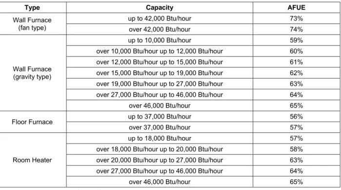
Non-central gas space heaters shall be certified to have AFUE values greater than or equal to those listed in Table 4-2 below:
Table 4-2 – Minimum Heating Efficiency for Non-Ducted, Non-Central Gas Fired Heating Equipment
Type Capacity AFUE
Wall Furnace (fan type) up to 42,000 Btu/hour 73% over 42,000 Btu/hour 74% Wall Furnace (gravity type) up to 10,000 Btu/hour 59% over 10,000 Btu/hour up to 12,000 Btu/hour 60% over 12,000 Btu/hour up to 15,000 Btu/hour 61% over 15,000 Btu/hour up to 19,000 Btu/hour 62% over 19,000 Btu/hour up to 27,000 Btu/hour 63% over 27,000 Btu/hour up to 46,000 Btu/hour 64% over 46,000 Btu/hour 65% Floor Furnace up to 37,000 Btu/hour 56% over 37,000 Btu/hour 57%
Room Heater
up to 18,000 Btu/hour 57% over 18,000 Btu/hour up to 20,000 Btu/hour 58% over 20,000 Btu/hour up to 27,000 Btu/hour 63% over 27,000 Btu/hour up to 46,000 Btu/hour 64% over 46,000 Btu/hour 65% Source: California Appliance Efficiency Regulations Table E-2
The AFUE of mobile home furnaces shall be certified not to be less than 75 percent.
Heat Pumps and Electric Heating
Table 4-3 summarizes the energy efficiency requirements for heat pumps. There are no minimum appliance efficiency standards for resistance or electric-radiant heating systems.
Table 4-3 – Minimum Heating Efficiency for Heat Pumps Equipment Type Appliance Efficiency Regulations Reference Configuration /
Size Minimum Heating Efficiency Room heat pumps Table B-2 Any Cooling standard only Packaged terminal heat
pumps Table B-3 Any 1.3 +[0.00016 x Cap)] COP
Single phase air source heat pumps (NAECA)
< 65,000 Btu/h Cooling Capacity Packaged 7.7 HSPF
1
Split 7.7 HSPF 1 Table C-2 < 65,000 Btu/h Cooling Capacity Through-the-wall See Appliance Efficiency Regulations
Small duct high velocity
< 65,000 Btu/h Cooling Capacity See Appliance Efficiency Regulations Three-phase air source
heat pumps Table C-3 < 65,000 Btu/h
See Appliance Efficiency Regulations Water-source heat
pumps Table C-5
< 135,000 Btu/h 4.2 COP
≥ 135,000 Btu/h, < 240,000 Btu/h 2.9 COP
1. HSPF values in parentheses indicate minimum efficiency effective January 23, 2006.
Source: California Appliance Efficiency Regulations
Heat Pump Controls §112(b), Exception to §112(c)
Any heat pump with supplementary electric resistance heating must have controls that have two capabilities to limit the electric resistance heating. The first is to set the cut-on and cut-off temperatures for compression and supplementary heating at different levels. For example, if the heat pump begins heating when the inside temperature reaches 68°F, the electric resistance heating is set to come on if the temperature gets below 65°F; and there is an opposite off mode such that if the heat pump shuts off when the temperature reaches 72°F, the back-up heating shuts off at 68°F.
The second control capability prevents the supplementary electric resistance heater from operating when the heat pump alone can meet the heating load, except during defrost. There is a limited exception to this second function for “smart thermostats” that provide the following: intelligent recovery, staging, ramping, or another control mechanism that prevents the unnecessary operation of supplementary electric resistance heating when the heat pump alone can meet the heating load.
To meet the thermostat requirements, a thermostat for a heat pump must be a “smart thermostat” that minimizes the use of supplementary heating during startup and recovery from setbacks.
Note: Room air conditioner heat pumps are not required to comply with the
Equipment Sizing §150(h)
The Standards do not set limits on the sizing of heating equipment, but they do require that heating loads be calculated for new heating systems. Oversized equipment typically operates less efficiently and can create comfort problems due to excessive cycling and high airflow.
Acceptable load calculation procedures include methods described in the
ASHRAE Handbook – Equipment, ASHRAE Handbook – Applications, ASHRAE Handbook – Fundamentals, SMACNA Residential Comfort System Installation Manual, or ACCA Manual J.
The Standards require that the outdoor design conditions for load calculations be selected from Reference Joint Appendix JA2, and that the indoor design
temperature for heating load calculations be 70°F. The outdoor design temperature must be no lower than the heating winter median of extremes as listed in the Reference Joint Appendix JA2. If the actual city location for a project is not included in the Reference Joint Appendix JA2, or if the data given for a particular city does not match the conditions at the actual site as well as that given for another nearby city, consult the local building department for guidance.
The load calculations must be submitted with compliance documentation when requested by the building department. The load calculations may be prepared by 1) the documentation author and submitted to the mechanical contractor, 2) a mechanical engineer, or 3) the mechanical contractor who is installing the equipment.
Standby Losses and Pilot Lights §115
Fan-type central furnaces may not have a continuously burning pilot light. This requirement does not apply to wall furnaces, floor furnaces or any gravity type furnace. Household cooking appliances also must not have a continuously burning pilot light except for those without an electrical supply voltage connection and in which each pilot consumes less than 150 Btu/hr.
§112(d)
Larger gas-fired and oil-fired forced air furnaces with input ratings ≥ 225,000 Btu/h (which is bigger than a typical residential furnace) must also have an intermittent ignition or interrupted device (IID), and either power venting or a flue damper. A vent damper is an acceptable alternative to a flue damper for furnaces where combustion air is drawn from the conditioned space. All furnaces with input ratings ≥ 225,000 Btu/h, including electric furnaces, that are not located within the conditioned space must have jacket losses not exceeding 0.75 percent of the input rating.
4.2.2 Prescriptive Requirements §151(f)6 Heating System Type
Prescriptive Packages D and E require that a gas heating system or a heat pump be installed. The minimum energy efficiency of the heating equipment is specified by the mandatory measures (see above).
Package C allows electric resistance and electric radiant heating, but insulation and other measures are more stringent.
Under the performance compliance method, a small credit is available for electric radiant panel heating systems relative to electric baseboard systems.
4.2.3 Compliance Options
With the performance compliance method, credit can be taken for selecting high efficiency heating equipment, such as a high efficiency furnace or heat pump. With a furnace, for example, the minimum requirement is an AFUE of 78 percent, but units are available with AFUE of 90 percent or better.
4.3 Cooling Equipment
This section addresses the requirements for primary cooling equipment.
4.3.1 Mandatory Measures Equipment Efficiency
§111 and §112(a)
Appliance Efficiency Regulations
The efficiency of most cooling equipment is regulated by NAECA (the federal appliance standard) and the California Appliance Efficiency Regulations. These regulations are not contained in the Building Energy Efficiency Standards but rather in separate documents. These regulations are referenced in §111. The Appliance Efficiency Regulations include definitions for all types of equipment. The energy efficiency of larger equipment is regulated by §112(a). See the Nonresidential Compliance Manual for information on larger equipment.
Central, Single Phase Air Conditioners and Air Source Heat Pumps (under 65,000 Btu/h)
The central, single phase air conditioners and air source heat pumps that are most commonly installed in residences have a smaller capacity than 65,000 Btu/h. The Appliance Efficiency Regulations for this equipment require minimum
The Seasonal Energy Efficiency Ratio of all new central, single phase air conditioners and air source heat pumps with output less than 65,000 Btu/h shall be certified not to be less than the values listed below.
Table 4-4 – Minimum Cooling Efficiencies for Central Air Conditioners and Heat Pumps
Appliance Type SEER
Central Air Conditioners Split System 13.0
Single Package 13.0
Central Air Source Heat Pumps Split System 13.0
Single Package 13.0
Source: California Appliance Efficiency Regulations Table C-2
Other Air Conditioners and Heat Pumps Appliance Efficiency Regulations
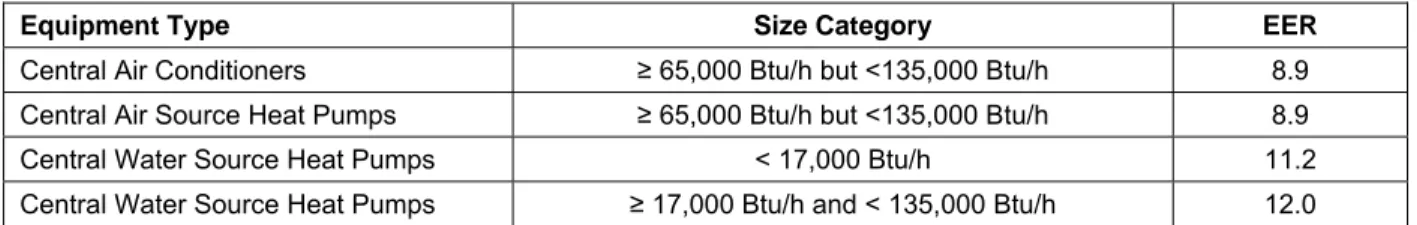
The current Appliance Efficiency Regulations for larger central air conditioners and heat pumps, and for all room air conditioners and room air conditioner heat pumps shall be certified by the manufacturer to not to be less than the values listed in Table 4-5 and Table 4-6.
Table 4-5 – Minimum Cooling Efficiency for Larger Central Air Conditioners and Heat Pumps
Equipment Type Size Category EER
Central Air Conditioners ≥ 65,000 Btu/h but <135,000 Btu/h 8.9 Central Air Source Heat Pumps ≥ 65,000 Btu/h but <135,000 Btu/h 8.9 Central Water Source Heat Pumps < 17,000 Btu/h 11.2 Central Water Source Heat Pumps ≥ 17,000 Btu/h and < 135,000 Btu/h 12.0
Table 4-6 – Minimum Cooling Efficiency for Non-Central Space Cooling Equipment
Including Room Air Conditioners; and Room Air Conditioner Heat Pumps; Package Terminal Air Conditioners (PTAC); and Package Terminal Heat Pumps (PTHP)
Equipment Type Size Category (Input) Minimum Efficiency
Room Air Conditioners, with Louvered Sides
< 6,000 Btu/h 9.7 EER
≥ 6,000 Btu/h and < 8,000 Btu/h 9.7 EER
≥ 8,000 Btu/h and < 14,000 Btu/h 9.8EER
≥ 14,000 Btu/h and < 20,000
Btu/h 9.7 EER
≥ 20,000 Btu/h 8.5 EER
Room Air Conditioners, without Louvered Sides
< 6,000 Btu/h 9.0 EER
≥ 6,000 Btu/h and < 8,000 Btu/h 9.0 EER
≥ 8,000 and <20,000 Btu/h 8.5 EER
≥ 20,000 Btu/h 8.5 EER Room Air Conditioner Heat Pumps
with Louvered Sides
< 20,000 Btu/h 9.0 EER
≥ 20,000 Btu/h 8.5 EER Room Air Conditioner Heat Pumps without
Louvered Sides
< 14,000 Btu/h 8.5EER
≥ 14,000 Btu/h 8.0 EER Casement-Only Room Air Conditioner All Capacities 8.7 EER Casement-Slider Room Air Conditioner All Capacities 9.5 EER
PTAC and PTHP
≤ 7,000 Btu/h 8.88 EER > 7,000 and
< 15,000 Btu/h 10.0 – (0.00016 x Cap) EER
≥ 15,000 Btu/h 7.6 EER Source: California Appliance Efficiency Regulations TablesB-2 and B-3
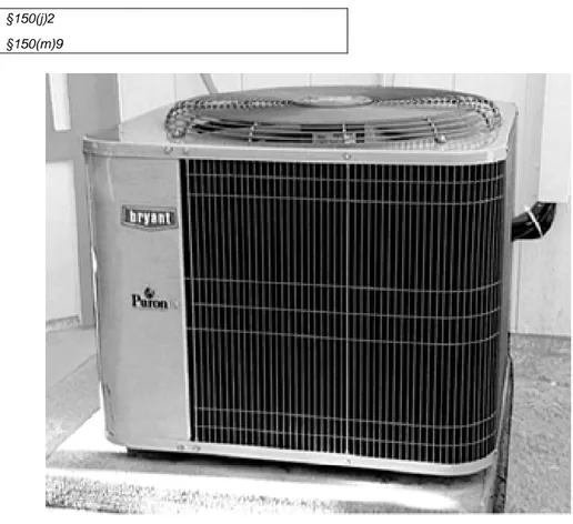
Insulation for Refrigerant Lines in Split System Air Conditioners §150(j)2
§150(m)9
Figure 4-1 – Outdoor Compressor/Condenser Unit
Two refrigerant lines connect the indoor and outdoor units of split system air conditioners and heat pumps: the liquid line (the smaller line) and the suction line (the larger line). The liquid line is at an elevated temperature, and heat escaping from it is helpful; therefore, it should not be insulated. However, the suction line carries refrigerant vapor that is cooler than ambient in the summer and (with heat pumps) warmer than ambient in the winter. This line, when less than or equal to 2 inches, (50 mm) in diameter must be insulated with at least 0.75 inches (19 mm) of insulation per the requirements of §150(j)2. When cooling systems contain suction lines greater than 2 inches in diameter, §150(j)2 requires a minimum insulation level of 1 inch (25 mm).
Figure 4-2 – Refrigerant Line Insulation
Insulation used with the suction line must be protected from physical damage or from UV deterioration. Pipe insulation in outdoor locations is typically protected by an aluminum or sheet metal jacket, painted canvas, plastic cover, or coating that is water retardant and UV resistant. See §150(m)9, and Figure 4-2.
Equipment Sizing §150(h), §151(b)
Just as for heating equipment, the Standards do not set limits on the size of cooling equipment, but they do require that cooling loads be calculated for new cooling systems. Avoiding oversizing is especially important for cooling equipment because efficiency degrades when the system cycles on and off frequently.
The Standards offer a compliance credit when the installed air conditioning equipment is sized in accordance with the Reference Residential Appendix RA1 Maximum Rated Cooling Capacity for compliance credit sizing calculations. A HERS rater field verification is required to confirm that the installed equipment conforms to the sizing criteria as reported on the CF-1R.
The outdoor design conditions for load calculations must be selected from Reference Joint Appendix JA2, Table 2-3, using values no greater than the 1.0 percent Cooling Dry Bulb and Mean Coincident Wet Bulb values listed. The indoor design temperature for cooling load calculations must be 75°F.
Cooling load calculations must be submitted with compliance documentation when requested by the building department. The load calculations may be prepared by:
1) The documentation author and submitted to the mechanical contractor, or
2) A mechanical engineer, or
3) The mechanical contractor who is installing the equipment.
4.3.2 Prescriptive Requirements §151(f)7
The prescriptive packages C, D, and E, for split system equipment in climate zones 2 and 8 through 15, require refrigerant charge measurement (RCM) and the installation of temperature measurement access holes (TMAH), and saturation temperature measurement sensors (STMS). The RCM must be HERS verified. TMAH and STMS make non-intrusive methods for HERS verification of RCM possible. The alternative to the RCM, TMAH, and STMS is the installation of a refrigerant charge indicator display (§151(f)7Aii).
Refrigerant Charge Measurement (RCM)
The prescriptive standards require that a HERS rater verify that split system air conditioners and heat pumps have the correct refrigerant charge. The RCM procedures that HERS raters are required to follow are documented in the Reference Residential Appendix RA3.2. Packaged units are not required to have refrigerant charge measurement.
The measurement and regulation of correct refrigerant charge can significantly improve the performance of air conditioning equipment. Refrigerants are the working fluids in air conditioning and heat pump systems that absorb heat energy from one area (the evaporator) and transfer it to another (the condenser).
Refrigerant charge refers to the actual amount of refrigerant present in the
system. Excessive refrigerant charge (overcharge) reduces system efficiency and can lead to premature compressor failure. Insufficient refrigerant charge
(undercharge) also reduces system efficiency and can cause compressors to overheat.
Temperature Measurement Access Holes (TMAH)
TMAH provide a non-intrusive means for refrigerant charge verification by HERS raters and other third party inspectors, since they eliminate the need for the raters/inspectors to drill holes into the installed air conditioning equipment enclosures for placement of the temperature sensors that are required by the refrigerant charge verification test procedures described in the Reference Residential Appendix RA3.2.
Installation of TMAH must be performed by the installer of the air conditioner or heat pump equipment according to the specifications given in Reference Residential Appendix RA3.2.
The TMAH feature consists of two 5/16 inch (8 mm) holes in the plenum, one upstream from the evaporator coil and one downstream from it (see diagram in Reference Residential Appendix RA3.2).
Saturation Temperature Measurement Sensors (STMS)
The STMS provide a non-intrusive means for refrigerant charge verification by HERS raters and other third party inspectors, since they eliminate the need for a rater/inspector to open the system's refrigerant service access ports to install refrigerant pressure gauges on the suction and discharge lines. The test procedures that utilize these STMS are described in the Reference Residential Appendix RA3.2.
The STMS feature consists of two permanently installed temperature sensors, one mounted on the evaporator coil and one mounted on the condenser coil. The sensors are required to be factory installed, or field installed according to
manufacturer’s specifications, or otherwise installed in accordance with an alternative installation/instrumentation specification that must be approved by the Executive Director. These STMS must be equipped with industry standard mini plugs that allow the system installers and HERS raters to use the sensors to measure the coil saturation temperature by attaching the temperature sensor mini plugs to a digital thermometer instrument.
To adjust or check the refrigerant charge on an air conditioning system using the standard charge measurement procedures in Reference Residential Appendix RA3.2, it is necessary to determine the instantaneous “saturation temperature” in the evaporator coil and in the condenser coil. A refrigeration technician typically determines this temperature by measuring the coil pressure and using a
saturation temperature chart to look up the saturation temperature at that pressure.
Another way to determine the saturation temperature in the coil is to measure the temperature of the refrigerant tubing in the saturation temperature region of one of the tubing circuits in the coil. The saturation temperature measurement is made utilizing a temperature sensor that has been permanently installed for this purpose by the equipment manufacturer or the air conditioning contractor. For a coil in a typical system operating at steady state, approximately 75 percent of the length of any tubing circuit in the coil will be at a constant saturation temperature and pressure (the refrigerant is undergoing a phase change). To determine the location of the saturation temperature region of the circuit, trace the path of the refrigerant tubing circuit from the inlet of the tubing circuit, to the outlet of the tubing circuit.
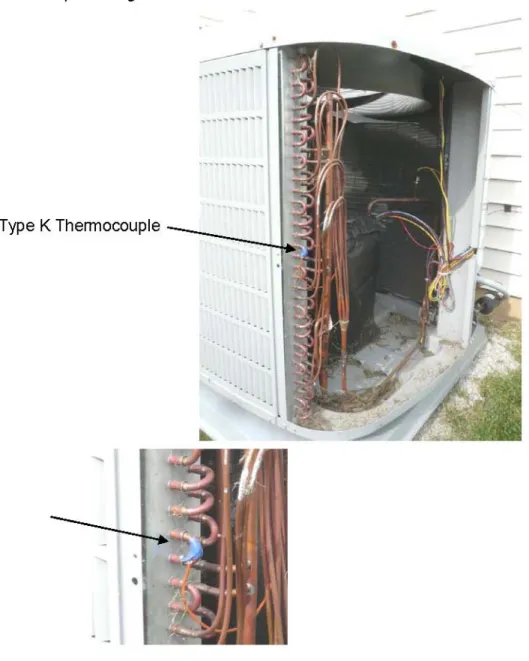
In the condenser coil, generally the first 10 to 20 percent of each tubing circuit contains superheated vapor; the center 60 to 80 percent of the tubing circuit contains refrigerant undergoing a phase change (condensing the vapor into a liquid at a constant temperature); and the last 10 to 20 percent of the tubing circuit contains sub-cooled liquid. Figure 4-3 shows a condenser coil with multiple tubing circuits, and a Type K thermocouple attached to the saturation temperature region of one of the tubing circuits.
In the evaporator coil, the first 60 percent or more of the circuit contains
refrigerant changing from liquid to vapor at the saturation temperature, and the last portion of the circuit contains superheated vapor. Figure 4-4 shows an evaporator coil with a simple tubing circuit.
Figure 4-4 – Evaporator Coil
Thermocouples shall be type K with the sensing tip permanently attached to the refrigerant piping and insulated with cork tape at the location specified by the equipment manufacturer. An industry standard plug shall be lead to the outside of the equipment where it will be accessible to technicians or HERS raters without any disassembly of the equipment.
If the manufacturer's thermocouple installation instructions are not available, the system designer shall include specifications on the system's design drawings for the installed location of the thermocouples. The air conditioning contractor shall install the thermocouple in good contact with the tube bend at the specified location and insulate it from the surrounding air to provide a direct measurement of the coil “saturation temperature”.
Charge Indicator Display
The installation of a charge indicator display (CID), if verified by a HERS rater, may be used as an alternative to the prescriptive requirement for HERS diagnostic testing of the refrigerant charge in split system air conditioners and heat pumps. The purpose of the CID is to provide real-time information to the building occupant about the status of the system refrigerant charge, metering device, and cooling coil airflow. The CID will monitor and determine the operating performance of split system air conditioners and heat pumps, and provide visual indication to the system owner or operator if the system’s refrigerant charge,
airflow, or metering device performance does not conform to approved target parameters for minimally efficient operation. Thus, if the CID signals the owner/occupant that the system requires service or repair, the occupant can immediately call for a service technician to make the necessary adjustments or repairs. A CID can provide significant benefit to the owner/occupant by alerting the owner/occupant to the presence of inefficient operation that could result in excessive energy use/costs over extended periods of time. A CID can also indicate system performance faults that could result in system component damage or failure if not corrected, thus helping the owner/occupant to avoid unnecessary repair costs.
Charge indicator display technologies shall be factory installed or field installed according to manufacturer's specifications. Reference Joint Appendix JA6 contains more information about CID technologies.
The presence of a CID on a system must be field verified by a HERS rater. See Reference Residential Appendix RA3.4.2 for the HERS verification procedure, which consists of a visual verification of the presence of the installed CID technology. The rater must inspect to see that the visual indication display component of the installed CID technology is mounted adjacent to the split system's thermostat. The rater must also observe that the system reports no system faults when the system is operated continuously for at least 15 minutes when the indoor air temperature returning to the air conditioner is above 65°F.
Cooling Coil Airflow; Fan Watt Draw; and Hole for the Placement of a Static Pressure Probe (HSPP) or Permanently Installed Static Pressure Probe (PSPP)
Prescriptively in climate zones 10 through 15 the central forced air system fans must maintain airflow greater than 350 CFM per nominal ton of cooling capacity across the cooling coil and have a fan watt draw less than 0.58 Watts/CFM. This measure is applicable under prescriptive packages C, D, and E. This measure requires builders to improve air handler fans and air conditioner efficiency by improving their duct systems and possibly by installing higher efficiency air handlers.
Reducing the watt draw of central forced air systems provides significant peak demand savings because they are generally running continuously on the hottest days when the electricity system peaks occur. Adequate airflow also provides peak demand savings because it increases the sensible Energy Efficiency Ratio (EER) of air conditioning systems, particularly at the high outdoor dry bulb temperatures on peak demand days. Adequate airflow and low watt draw save electricity throughout the cooling season, and low fan watt draw saves electricity in the heating season as well.
When cooling coil airflow and fan watt draw is required prescriptively, there must be a hole, provided in the supply plenum by the installing contractor, for the placement of a static pressure probe (HSPP) or a permanently installed static pressure probe (PSPP) must be installed. The HSPP or PSPP must be installed in the required location, in accordance with the specifications detailed in
Reference Residential Appendix RA3.3. The HSPP or PSPP is required in order to facilitate cooling coil airflow measurement when using devices/procedures that depend on supply plenum pressure measurements. The HSPP or PSPP allows HERS raters to perform the required diagnostic airflow testing in a non-intrusive
manner, by eliminating the necessity for the rater to drill holes in the supply plenum for placement of pressure measurement probes.
There are three acceptable methods allowed for use in determining compliance with the cooling coil airflow requirement as described in Reference Residential Appendix RA3.3:
• use of a flow capture hood to measure the total airflow through the return grill(s), or
• a flow grid device at the return grill(s) or other location where all the central fan airflow passes through the flow grid, or
• using a fan flow meter device to perform the plenum pressure matching procedure.
The flow grid measurement device, and the fan flow meter measurement device both require access to static pressure measurements of the airflow exiting the cooling coil, which utilizes the HSPP or PSPP mentioned above.
Heating-only space-conditioning systems are not required to meet the prescriptive cooling coil airflow and fan watt draw requirements.
The airflow measurement procedures described in Reference Residential
Appendix RA3.3 are also allowed to be used for determining compliance with the minimum airflow requirement for the refrigerant charge verification protocol - as an alternative to using the temperature split method that is described in the Reference Residential Appendix RA3.2. However, the temperature split method is not allowed to be used to determine compliance with the cooling coil airflow requirements.
4.3.3 Compliance Options
There are several options for receiving compliance credit related to the cooling system. These credits are available through the performance compliance method.
High Efficiency Air Conditioner
Air conditioner efficiencies are determined according to federal test procedures. The efficiencies are reported in terms of Seasonal Energy Efficiency Rating (SEER) and Energy Efficiency Rating (EER). Savings can be achieved by choosing an air conditioner that exceeds the minimum efficiency requirements. The EER is the full load efficiency at specific operating conditions. It is possible that two units with the same SEER can have different EERs. In cooling climate zones of California, for two units with a given SEER, the unit with the higher EER is more effective in saving energy. Using the performance compliance method, credit is available for specifying an air conditioner with an EER greater than 10 (see the compliance program vendor’s compliance supplement). When credit is taken for a high EER, field verification by a HERS rater is required (see Reference Residential Appendix RA3.4).
Air Handler Watt Draw
All the prescriptive packages require central forced air systems to install a fan that draws less than 0.58 watts/CFM. Performance compliance credit is available for demonstrating the installation of a high efficiency fan and duct system with a lower wattage fan than the prescriptive requirement. This credit can be achieved by selecting a unit with a high efficiency air handler fan and/or careful attention to efficient duct design. The performance compliance method allows the user’s proposed fan power to be entered into the program, and credit will be earned if it is lower than the default of 0.58 watts per CFM of cooling coil airflow. To obtain this credit, the cooling coil airflow must meet the prescriptive requirements of at least 350 CFM/ton of nominal cooling capacity. After installation, the contractor must test the actual fan power of each system using the procedure in Reference Residential Appendix RA3.3, and show that it is equal or less than what was proposed in the compliance software analysis. For meet prescriptive compliance the cooling coil airflow criteria shall be 350 CFM/ton of nominal cooling capacity or greater. See §151(f)7B. The watt draw and airflow must also be verified by a HERS rater.
Cooling Coil Airflow
Adequate cooling coil airflow rates must be attained in order to deliver an air conditioner's maximum rated sensible capacity, total capacity, and efficiency. Low airflow rates can lead to ice buildup on the cooling coil and to compressor failure. §151(f)7Bi requires a prescriptive airflow rate of at least 350 CFM/ton of nominal cooling capacity. The performance approach offers a compliance credit for systems that can demonstrate a cooling coil airflow that exceeds 350 CFM/ton of nominal cooling capacity. The air handler must meet the prescriptive requirement for fan Watt draw of less than 0.58 w/CFM. The airflow for each system that must demonstrate compliance must be tested using one of the methods described in Reference Residential Appendix RA3.3. This compliance requires verification by a HERS rater.
Maximum Rated Total Cooling Capacity (MRTCC)
Compliance credit is available for cooling systems that have rated total cooling capacities that are less than the maximum rated total cooling capacity (MRTCC) criteria calculated by the Compliance Software for the proposed design as shown on the CF-1R. The installed equipment must be verified by a HERS rater to confirm compliance with the MRTCC criteria shown on the CF-1R. This
compliance credit is available only in combination with the credits for duct sealing, and prescriptive cooling coil airflow.
The Electrical Input Exception for the MRTCC credit described in Reference Residential Appendix RA1.4 may be used to achieve the same compliance credit allowed for MRTCC. This exception allows compliance credit for equipment with rated total cooling capacity that exceeds the MRTCC criteria if the selected equipment does not use more power than the minimally compliant MRTCC equipment. Selection of EER values above the default 10 EER are used to attain compliance with this exception. An EER verification and MRTCC verification of the installation by a HERS rater is required if this electrical input exception is
claimed. Cooling coil airflow and duct sealing verification by a HERS rater is required.
The procedure for field verification of high EER equipment is described in Reference Residential Appendix RA3.4.4. The procedure consists of visual verification of installed equipment and confirmation that the installed equipment matches the equipment required to achieve the high EER rating based on the AHRI rating for the equipment. The procedures for duct leakage measurements are specified in Reference Residential Appendix RA3.1. The procedures for cooling coil airflow verification are specified in Reference Residential Appendix RA3.3.
4.4 Air Distribution Ducts and Plenums
Air distribution system performance can have a big impact on overall HVAC system efficiency. Therefore, air distribution systems face a number of mandatory measures and prescriptive requirements. The prescriptive requirements say that air distribution ducts must be sealed and tested in all climate zones. There are also a number of compliance credits available related to duct system design. Duct efficiency is affected by the following parameters:
• Duct location (attic, crawlspace, basement, inside conditioned space, or other)
• Specific conditions in the unconditioned space, e.g., presence of a radiant barrier
• Duct insulation characteristics
• Duct surface area, and
• Air leakage of the duct system
In performance calculations, duct efficiency can be calculated in one of two ways:
• default input assumptions; or
• diagnostic measurement values.
The computer program will use default assumptions for the proposed design when the user does not intend to make improvements in duct efficiency. There is a compliance penalty if the ducts are not sealed and tested.
4.4.1 Mandatory Measures Minimum Insulation
§150(m)1
In all cases, unless ducts are enclosed entirely in conditioned space, the minimum allowed duct insulation value is R-4.2. Note that higher values may be required by the prescriptive requirements as described below.
§150(m)5
For the purpose of determining installed R-value of duct wrap, the installed thickness of insulation must be assumed to be 75 percent of the nominal thickness due to compression.
Connections and Closures §150(m)1, §150(m)2, §150(m)3
The Standards set a number of mandatory measures related to duct connections and closures. These measures address both the materials used for duct sealing and the methods that may be used. Refer to the sections of the Standards listed above for details.
Connections between metal ducts and the inner core of flexible ducts must be mechanically fastened.
Factory-fabricated Duct Systems
Factory fabricated duct systems must comply with the following requirements: 1. All factory-fabricated duct systems must comply with UL 181 for
ducts and closure systems, including collars, connections, and splices, and be labeled as complying with UL 181. UL181 testing may be performed by UL laboratories or a laboratory approved by the Executive Director.
2. All pressure-sensitive tapes, heat-activated tapes, and mastics used in the manufacture of rigid fiberglass ducts must comply with UL 181 and UL 181A.
3. All pressure-sensitive tapes and mastics used with flexible ducts must comply with UL 181 and UL 181B.
4. Joints and seams of duct systems and their components cannot be sealed with cloth back rubber adhesive duct tapes unless such tape is used in combination with mastic and draw bands: or 5. It has on its backing the phrase "CEC approved," a drawing of a
fitting to plenum joint in a red circle with a slash through it (the international symbol of prohibition), and a statement that it cannot be used to seal fitting to plenum and junction box joints.
Field-fabricated Duct Systems
Field –fabricated duct systems must comply with the following requirements: 1. Factory-made rigid fiberglass and flexible ducts for field-fabricated
duct systems must comply with UL 181.All pressure-sensitive tapes, mastics, aerosol sealants, or other closure systems used for installing field-fabricated duct systems shall meet the applicable requirements of UL 181, UL 181A, and UL 181B.
3. Sealants must comply with the applicable requirements of UL 181, UL 181A, and/or UL 181B, and be nontoxic and water resistant. 4. Sealants for interior applications must be tested in accordance with
ASTM C731 and D2202.
5. Sealants for exterior applications must be tested in accordance with ASTM C731, C732, and D 2202.
6. Sealants and meshes must be rated for exterior use.
7. Pressure-sensitive tape. Pressure-sensitive tapes must comply with the applicable requirements of UL 181, UL 181A, and UL 181B.
8. Joints and seams of duct systems and their components must not be sealed with cloth back rubber adhesive duct tapes unless such tape is used in combination with mastic and draw bands: or 9. It has on its backing the phrase "CEC approved," a drawing of a
fitting to plenum joint in a red circle with a slash through it (the international symbol of prohibition), and a statement that it cannot be used to seal fitting to plenum and junction box joints.
Draw Bands Used With Flexible Duct
1. Draw bands must be either stainless-steel worm-drive hose clamps or UV-resistant nylon duct ties.
2. Draw bands must have a minimum tensile strength rating of 150 pounds.
3. Draw bands must be tightened as recommended by the manufacturer with an adjustable tensioning tool.
Aerosol-sealant Closures
1. Aerosol sealants shall meet the requirements of UL 723 and be applied according to manufacturer specifications.
2. Tapes or mastics used in combination with aerosol sealing shall meet the requirements of this Section.
If mastic or tape is used to seal openings greater than 1/4 inch, the combination of mastic and either mesh or tape must be used.
Building spaces such as cavities between walls, support platforms for air handlers, and plenums defined or constructed with materials other than sealed sheet metal, duct board, or flexible duct must not be used for conveying
conditioned air including return air and supply air. The practice of using drywall materials as the interior surface of a return plenum is not allowed. Building cavities and support platforms may contain ducts. Ducts installed in cavities and support platforms must not be compressed to cause reductions in the cross sectional area of the ducts. Although a HERS rater may examine this as a part of his or her responsibilities when involved in a project, the enforcement of these minimum standards for ducts is the responsibility of the building official.
Example 4-1 Question
I am installing a fan coil in the hallway of a multifamily dwelling unit in a space constructed of sheetrock. The sheetrocked space is formed by the original hallway ceiling at the top, the hallway sidewalls, and sheetrock across the bottom of the space with a return grill mounted in the bottom sheetrock. Does a duct have to be installed connecting the fan coil return to the return register?
Answer
This type of installation may be used only when a fan-coil unit is installed in a sheetrocked space that is constructed and sealed to meet all applicable requirements in the California Building Code (CBC) Title 24, Part 2, Volume 1, Chapter 7 for fire-resistance-rated construction.
Also, §150(m) states as follows:
“Building cavities, support platforms for air handlers, and plenums defined or constructed with materials other than sealed sheet metal, duct board or flexible duct shall not be used for conveying conditioned air.”
There are two acceptable methods of complying with §150(m) for the fan coil space that is the subject of the question.
1. A return duct is installed between the fan coil and the return register.
2. If the builder demonstrates that the sheetrocked space in which the fan coil is installed is not a plenum, the duct in method “1” is not required.
The California Mechanical Code has the following definition of a plenum:
“PLENUM is an air compartment or chamber including uninhabited crawl spaces, areas above ceilings or below a floor, including air spaces below raised floors of computer/data processing centers, or attic spaces, to which one or more ducts are connected and which forms part of either the supply air, return air or exhaust air system, other than the occupied space being conditioned.”
To demonstrate the sheetrocked space in which the fan coil is installed is not a plenum, the builder must demonstrate that it is part of the conditioned space. This fan coil space can be considered part of the conditioned space if it is demonstrated that the space
1. is within the building envelope, and
2. air leakage pathways (e.g., infiltration connections to building cavities) are sealed such that the space is more connected to the inside of the envelope than to outside the envelope. There are two ways of demonstrating that air leakage pathways are properly sealed. 1. The easiest way is to construct the fan coil space so that an inspector is able to visually determine that the space has no leakage paths. No testing is required for this approach. The inspector must be able to inspect all joints and seams in the sheetrock, particularly horizontal seams that are above and below the sheetrocked bottom of the space, and to verify that no horizontal seams are behind the sheetrocked bottom or the mounting supports for the
sheetrocked bottom of the space. The supports for the sheetrocked bottom must be mounted on the surface of the walls of the space and have sheetrock between the support and the wall framing.
Any horizontal seam in the wall-mounted sheetrock must be a minimum of ½ inch below the lower surface of the sheetrocked bottom. Also any horizontal seam in the wall of the space above the sheetrocked bottom must be a minimum of 1½ inches above the top of the mounting wood or metal brackets. This spacing is required to allow adequate room for taping the seam. All vertical sheetrock seams must be taped and sealed with joint compound or equivalent prior to the installation of the wood or metal brackets that support the dropped ceiling.
All penetrations of this space, for example refrigerant lines, water lines for hydronic heating, electrical (line and low voltage) lines, sprinkler lines, and ducts must be sealed with fire caulk or other approved sealing material as required by the building official.
Ductwork that penetrates the sheetrock must use a collar that goes entirely through the wall cavity. These collars must extend at least two inches past the sheetrock on each side of the wall cavity. The collars must then be sealed to the sheetrock on each side of the wall. The ducts must be attached and sealed to the collar.
2. The other way to demonstrate there is no air leakage pathway that is more connected to the outside than to the inside is to test the leakage of the sheetrocked space as though it were a duct. For this test, the space is sealed off and tested with duct pressurization equipment at a pressure of 25 Pa. If the tested leakage from this space is 10 cfm or less, then the space may be considered to have no substantial leakage to outside the conditioned space (effectively zero within the instrumentation accuracy). The results of this test must be reported to the building official. See the following three figures.
Figure 4-6 – Example of metal bracket support to meet fire code separation
§150(m)1 Exception to §150(m)1
Ducts and fans integral to a wood heater or fireplace are exempt from these insulation and installation requirements.
§150(m)2D, §150(m)3D
Duct systems may not use cloth-back, rubber-adhesive duct tape unless it is installed in combination with mastic and draw bands. The enforcement of these minimum standards is the responsibility of the building official.
Product Markings §150(m)2A, §150(m)6
All factory-fabricated duct systems must meet UL 181 for ducts and closure systems and be labeled as complying with UL 181. Collars, connections and
splices are considered to be factory-fabricated duct systems and must meet the same requirement.
Insulated flexible duct products installed to meet this requirement must include labels, in maximum intervals of 3 ft, showing the R-value for the duct insulation (excluding air films, vapor barriers, or other duct components), based on the tests and thickness specified in §150(m).
Dampers to Prevent Air Leakage §150(m)7
Fan systems that exhaust air from the building to the outside must be provided with back draft or automatic dampers.
§150(m)8
Gravity ventilating systems must have an automatic or readily accessible,
manually operated damper in all openings to the outside, except combustion inlet and outlet air openings and elevator shaft vents. This includes clothes dryer exhaust vents when installed in conditioned space.
Protection of Insulation §150(m)9
Insulation must be protected from damage, including that due to sunlight, moisture, equipment maintenance, and wind but not limited to the following: Insulation exposed to weather must be suitable for outdoor service; for example, protected by aluminum, sheet metal, painted canvas, or plastic cover. Cellular foam insulation shall be protected as above or painted with a coating that is water retardant and provides shielding from solar radiation that can cause degradation of the material.
Ducts in Concrete Slab
Ducts located in a concrete slab must have R-4.2 insulation, but other issues will come into play. If ducts are located in the soil beneath the slab or embedded in the slab, the insulation material should be designed and rated for such
installation. Insulation installed in below-grade applications should resist moisture penetration (closed cell foam is one moisture-resistant product). Common pre-manufactured duct systems are not suitable for below-grade installations. If concrete is to be poured directly over the ducts, then the duct construction and insulation system should be sturdy enough to resist the pressure and not collapse. Insulation should be of a type that will not compress, or it should be located inside a rigid duct enclosure. The only time that common flex ducts are suitable in a below-grade application is when a channel is provided in the slab.
Indoor Air Quality and Mechanical Ventilation §150(o)
4.4.2 Prescriptive Requirements Duct Insulation
§151(f)10
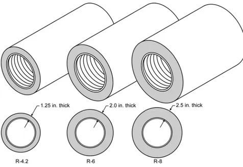
For Package C, the duct insulation requirement is R-8 in all climate zones. For Packages D& E, the requirement varies between R-4.2 and R-8.0 depending on climate zone. See Standards Tables 151-C & 151-D (reproduced in Appendix B of this document) for details.
Duct Leakage §151(f)10
Duct sealing, including field verification and diagnostic testing, is required in all climate zones for all three prescriptive packages C, D and E. The details of the testing methods are covered in RA3.1 of the Reference Residential Appendix. The bottom line requirement for new duct systems is that leakage is less than 6 percent of the supply airflow. (Note that the requirement is slightly less stringent for testing of existing duct systems as described in Chapter 8 of this Compliance Manual, Additions and Alterations).
To comply with the duct-sealing requirement, the installer must first perform the tests and document the results in the applicable portion of the CF-6R form. In addition, a HERS rater must provide independent diagnostic testing and verification and then record the findings on the CF-4R form.
Figure 4-7 – R-4.2, R-6, and R-8 Ducts
The alternative to duct testing is to use the performance compliance method. In this case, the computer program will automatically assume that the standard design (baseline) has been tested and sealed, while the proposed design will default to a higher leakage value.
4.4.3 Compliance Options
The Standards provide credit for several compliance options related to duct design and construction. These options are described below along with some general duct construction guidelines.
Supply Duct Location
There are three ways to achieve credit for favorable duct location when using the performance compliance method.
First, credit is available if no more than 12 LF (linear feet) of supply duct are outside conditioned space. This total must include the air handler and plenum length. This credit results in a reduction of duct surface area in the computer compliance programs. This option requires certification by the installer and field verification by a HERS rater.
The second alternative applies when 100 percent of the supply ducts are located in either the crawlspace or the basement rather than in the attic. To achieve this credit, a duct layout must be included in the plans showing that all supply registers are located in the floor (or at least no more than 2 ft above the floor). The compliance software will include this measure on the Certificate of
Compliance in the Special Features Inspection Checklist. This option does not require field verification by a HERS rater.
Third, credit for a high efficiency duct design is available through the Diagnostic Supply Duct Location, Surface Area, and R-value compliance option, which is described below. This option requires field verification of the duct design layout drawing(s) by a HERS rater. Verified duct design, when required, will be included in the HERS Required Verification list on the Certificate of Compliance (CF-1R). There is no compliance credit provided for choosing a heating system such as a wall furnace, floor heater, or room heater even though those systems typically have no ducts. For these cases, the standard design in the compliance calculation uses the same type of system and also has no ducts. However, other systems, such as hydronic heating systems with a central heater or boiler and multiple terminal units, are considered central HVAC systems that are compared to a ducted system in the Standard Design. If the hydronic system has no ducts, there may be a significant energy credit through the performance method.
Figure 4-8 – Example: Buried Ducts on Ceiling and Deeply Buried Ducts
Duct Insulation
Performance credit is also available if all of the ducts are insulated to a level higher than required by the prescriptive package. If ducts with multiple R-values are installed, the lowest duct R-value must be used for the entire duct system. However, the air handler, plenum, connectors, and boots can be insulated to the mandatory minimum R-value.
As an alternative when there is a mix of duct insulation R-values, credit is available through the method described in the next section.
Diagnostic Supply Duct Location, Surface Area, and R-value
This compliance option allows the designer to take credit for a high efficiency duct design that incorporates duct system features that do not meet the criteria for the duct location and/or insulation compliance options described above. This method requires that the designer must enter the design characteristics of all supply ducts that are not located within conditioned space. The information required for the
input to the compliance software includes the length, diameter, insulation R-value, and location of all supply ducts. This method will result in a credit if the proposed duct system is better than the standard design, which exactly meets the
prescriptive insulation requirement and has supply duct surface area set at 27 percent of floor area.
In order to claim this credit, the duct system design must be documented on plans that are submitted to the enforcement agency and posted at the construction site for use by the installation persons, the enforcement agency field inspector, and the HERS rater (Verified Duct Design). The duct system must be installed in accordance with the approved duct system plans, and the duct system installation must be certified by the installer on the CF-6R form and verified by a HERS rater on the CF-4R form. Details of this compliance option are described in Section 3.12.3 of the Residential ACM Manual, and verification procedures are described in RA3.1 of the Reference Residential Appendix.
This compliance option also allows credit for the special case of ducts that are buried by blown attic insulation. For ducts that lie on the ceiling (or within 3.5 inch of the ceiling), the effective R-value is calculated based on the duct size and the depth of ceiling insulation as shown in Table R3-38 in the Residential ACM Manual. This case is referred to as “Buried Ducts on the Ceiling”. For the case of Deeply Buried Ducts, which are ducts that are enclosed in a lowered portion of the ceiling and completely covered by attic insulation, then the effective R-value allowance in the compliance calculations is R-25 when the attic insulation is fiberglass and R-31 for cellulose attic insulation. In order to take credit for buried ducts, the system must meet the verified duct design criteria described above, be diagnostically tested for duct sealing compliance by a HERS rater according to Reference Residential Appendix RA3.1, and meet the requirements for high insulation installation quality described in Reference Residential Appendix RA3.5. Verified prescriptive cooling coil airflow is required when a measure is selected for compliance that has a verified duct design as a prerequisite.
Ducts in Attics with Radiant Barriers
Installation of a radiant barrier in the attic increases the duct efficiency by lowering attic summer temperatures. Compliance credit for radiant barriers requires listing of the radiant barrier in the Special Features and Modeling Assumptions in order to aid the local enforcement agency’s inspections. Compliance credit for a radiant barrier does not require HERS rater verification.
4.4.4 Duct Installation Standards
The mandatory duct construction measures referenced in Section 4.4.1 above state that duct installations must comply with 2007 California Mechanical Code Sections 601, 602, 603, 604, 605, and the applicable requirements of the 2008 California Building Energy Efficiency Standards. Some of the highlights of these requirements are listed in this section along with some guidance for
recommended quality construction practice.
Tapes and Clamps
Cloth-back rubber-adhesive tapes must be used only in combination with mastic and draw bands, or have on its backing the phrase "CEC approved," a drawing of a fitting to plenum joint in a red circle with a slash through it (the international symbol of prohibition), and a statement that it cannot be used to seal fitting to plenum and junction box joints.
All Joints Must Be Mechanically Fastened
For residential round metal ducts, installers must overlap the joint by at least 1½ inch and use three sheet metal screws equally spaced around the joint (see Figure 4-9).
Source: Richard Heath & Associates/Pacific Gas & Electric
Figure 4-9 – Connecting Round Metallic Ducts
For round non-metallic flex ducts, installers must insert the core over the metal collar or fitting by at least 1 in. This connection may be completed with either mesh, mastic and a clamp, or two wraps of tape and a clamp.
For the mesh and mastic connection, the installer must first tighten the clamp over the overlapping section of the core, apply a coat of mastic covering both the metal collar and the core by at least 1 in., and then firmly press the fiber mesh into the mastic and cover with a second coat of mastic over the fiber mesh (see Figure 4-10).
Source: Richard Heath & Associates/Pacific Gas & Electric
Figure 4-10 – Connecting Flex Ducts Using Mastic and Mesh
For the tape connection first apply at least two wraps of approved tape covering both the core and the metal collar by at least 1 inch, then tighten the clamp over the overlapping section of the core (see Figure 4-11).
Source: Richard Heath & Associates/Pacific Gas & Electric
Figure 4-11 –Connecting Flex Ducts Using Tape and Clamps
All Joints Must Be Made Airtight (§150(m))
Seal joints with mastic, tape, aerosol sealant, or other duct-closure system that meets the applicable requirements of UL 181, UL 181A, UL 181B, or UL 723. Duct systems shall not use cloth-back, rubber-adhesive duct tape regardless of UL designation, unless it is installed in combination with mastic and clamps. The Energy Commission has approved three cloth-back duct tapes with special butyl
synthetic adhesives rather than rubber adhesive to seal flex duct to fittings. These tapes are:
• Polyken 558CA, Nashua 558CA, manufactured by Berry Plastics Tapes and Coatings Division and
• Shurtape PC 858CA, manufactured by Shurtape Technologies, Inc. These tapes passed Lawrence Berkeley Laboratory tests comparable to those that cloth-back rubber-adhesive duct tapes failed (the LBNL test procedure has been adopted by the American Society of Testing and Materials as ASTM
E2342-03). These tapes are allowed to be used to seal flex duct to fittings without being in combination with mastic. These tapes cannot be used to seal other duct system joints, such as the attachment of fittings to plenums and junction boxes. These tapes have on their backing a drawing of a fitting to plenum joint in a red circle with a slash through it (the international symbol of prohibition) to illustrate where they are not allowed to be used, and installation instructions in their packing boxes that explain how to install them on duct core to fittings and a statement that the tapes cannot be used to seal fitting to plenum and junction box joints.
Mastic and mesh should be used where round or oval ducts join flat or round plenums (see Figure 4-12).
Source: Richard Heath & Associates/Pacific Gas & Electric
Figure 4-12 – Sealing Metallic Ducts with Mastic and Mesh All ducts must be adequately supported.
Both rigid duct and flex duct may be supported on rigid building materials between ceiling joists or on ceiling joists.
For rigid round metal ducts that are suspended from above, hangers must occur 12 ft apart or less (see Figure 4-13).
Source: Richard Heath & Associates/Pacific Gas & Electric
Figure 4-13 – Options for Suspending Rigid Round Metal Ducts
For rectangular metal ducts that are suspended from above, hangers must occur at a minimum of 4 ft to 10 ft depending on the size of the ducts (see Table 6-2-A in Appendix A of the 2007 California Mechanical Code). Refer to Figure 4-14.
Source: Richard Heath & Associates/Pacific Gas & Electric
Figure 4-14 – Options for Suspending Rectangular Metal Ducts
For flex ducts that are suspended from above, hangers must occur at 4 ft apart or less and all fittings and accessories must be supported separately by hangers (see Figure 4-15).
Source: Richard Heath & Associates/Pacific Gas & Electric
Figure 4-15 – Minimum Spacing for Suspended Flex Ducts
For vertical runs of flex duct, support must occur at 6 ft intervals or less (see Figure 4-16)
Source: Richard Heath & Associates/Pacific Gas & Electric
Figure 4-16 – Minimum Spacing for Supporting Vertical Flex Ducts
The routing and length of all duct systems can have significant impacts on system performance due to possible increased airflow resistance. The Energy
Commission recommends using the minimum length of duct to make connections and the minimum possible number of turns.
For flexible duct, the Energy Commission recommends fully extending the duct by pulling the duct tight and cutting off any excess duct and avoiding bending ducts across sharp corners or compressing them to fit between framing members (see Figure 4-17). Also avoid incidental contact with metal fixtures, pipes, or conduits or installation of the duct near hot equipment such as furnaces, boilers, or steam pipes that are above the recommended flexible duct use temperature.
Source: Richard Heath & Associates/Pacific Gas & Electric
Figure 4-17 – Minimizing Radius for Flex Duct Bends
All joints between two sections of duct must be mechanically fastened and
substantially airtight. For flex duct this must consist of a metal sleeve no less than 4 inch in length between the two sections of flex duct.
All joints must be properly insulated. For flex ducts this must consist of pulling the insulation and jacket back over the joint and using a clamp or two wraps of tape. Aerosol sealant injection systems are an alternative that typically combines duct testing and duct sealing in one process. Figure 4-18 shows the
computer-controlled injection fan temporarily connected to the supply duct. The plenum is blocked off by sheet metal to prevent sealant from entering the furnace. Supply air registers are also blocked temporarily to keep the sealant out of the house. Note that ducts must still be mechanically fastened even if an aerosol sealant system is used.
Source: Richard Heath & Associates/Pacific Gas & Electric
Figure 4-18 – Computer-Controlled Aerosol Injection System
4.5 Controls
4.5.1 Thermostats
Automatic setback thermostats can add both comfort and convenience to a home. Occupants can wake up to a warm house in the winter and come home to a cool house in the summer without using unnecessary energy.
§151(f)9
A thermostat is always required for central systems whether the prescriptive or performance compliance method is used. An exception is allowed only if: (1) the building complied using a computer performance approach with a non-setback thermostat; and
(2) the system is one of the following non-central types: