Introduction
This nonproprietary Cryptographic Module Security Policy describes how Cisco 7140 VPN routers meet the security requirements of the Federal Information Processing Standards (FIPS) 140-1, and how they operate in a secure FIPS 140-1 mode. The policy was prepared as part of the Level 2 FIPS 140-1 certification of Cisco 7140 VPN routers.
Note This document may be copied in its entirety and without modification. All copies must include the copyright notice and statements on the last page.
The FIPS 140-1 publication, “Security Requirements for Cryptographic Modules” details the U.S. Government requirements for cryptographic modules. More information about the FIPS 140-1 standard and validation program is available at the following National Institute of Standards and Technology (NIST) website:
http://csrc.nist.gov/cryptval/
This document contains the following sections:
• Introduction, page 1
• Cisco 7140 VPN Routers, page 2
• Secure Operation of the Cisco 7140 VPN Router, page 10
• Obtaining Documentation, page 12
• Obtaining Technical Assistance, page 13
References
This document deals with operations and capabilities of Cisco 7140 VPN routers in the technical terms of a FIPS 140-1 cryptographic module security policy. For more information on Cisco 7140 VPN routers and the entire Cisco 7100 VPN series, check the following sources:
• The Cisco Systems website contains information on the full line of Cisco Systems products. Refer to the following website:
www.cisco.com.
• The Cisco 7100 VPN series product descriptions can be found at the following website: www.cisco.com/warp/public/cc/pd/rt/7100/
• For answers to technical or sales related questions, please refer to the contacts listed on the following website:
www.cisco.com.
Terminology
In this document, the cryptographic module is referred to as the 7140 VPN router, the router, or the system.
Document Organization
The security policy document is part of the complete FIPS 140-1 Submission Package. In addition to this document, the complete submission package contains:
• Vendor evidence document
• Finite state machine
• Module software listing
• Other supporting documentation as additional references
This document provides an overview of Cisco 7140 VPN routers and explains the secure configuration and operation of the router. It also explains the general features and functionality of Cisco 7140 VPN routers and addresses the required configuration for the FIPS mode of operation.
Note This security policy and other certification submission documentation was produced by Corsec Security, Inc., under contract to Cisco Systems. With the exception of this nonproprietary security policy, the FIPS 140-1 Certification Submission documentation is Cisco-proprietary and can be released only under appropriate nondisclosure agreements. For access to these documents, please contact Cisco Systems.
Cisco 7140 VPN Routers
Cisco 7140 VPN routers provide superior routing and VPN services performance for the most demanding VPN deployments, as well as dual WAN interfaces and power supplies for increased VPN solution reliability. Cisco 7140 VPN routers integrate key features of VPNs—tunneling, data encryption, security, firewall, advanced bandwidth management, and service-level validation—to deliver
self-healing, self-defending site-to-site VPN platforms that better and more cost-effectively accommodate remote-office and extranet connectivity using public data services.
Cisco 7140 VPN routers offer specific hardware configurations and a processing architecture optimized for VPN applications and Customer Premises Equipment (CPE) environments, delivering turnkey VPN solutions for headend locations. Cisco 7140 VPN routers feature integrated LAN interfaces for connectivity to the corporate LAN or VPN termination behind the WAN edge, as well as optional
multiport WAN interfaces, providing multihomed connectivity to the VPN cloud. With its MIPS RISC processor, Cisco 7140 VPN routers deliver robust VPN features, such as bandwidth management and firewall, at speeds greater than 90 Mbps, as well as scalable tunneling and encryption services. Cisco 7140 VPN routers are further customizable through hardware and software options to accommodate diverse network architectures and requirements. An open expansion slot enables LAN/WAN interface customization by utilizing a Cisco 7000 family port adapter. Highly scalable tunneling and encryption is provided by the Integrated Services Module (ISM), which is described later in this document. With scalable support for IPSec, PPTP/MPPE, and L2TP, Cisco 7140 VPN routers provide flexibility in remote access deployment models for enterprises with both remote access and site-to-site VPN requirements. Advanced perimeter security and intrusion detection, key features in a self-defending VPN solution, are also provided on Cisco 7140 VPN routers via the Cisco IOS Firewall Feature Set.
Cisco 7140 VPN routers are available in seven models. Key features common to all models include:
• High-speed MIPS RISC 7000 series processor, delivering superior routing performance and robust VPN features
• Greater than 90-Mbps throughput of VPN services such as bandwidth management and firewall
• 64-MB system memory for reliable, high-speed VPN services delivery—expandable to 256 MB
• 64-MB packet memory for advanced bandwidth management services and long-delay networks
• 48-MB Flash disk for storing Cisco IOS software images
• Dual autosensing 10/100BaseT Fast Ethernet ports, RJ-45 interfaces
• Integrated WAN interface
• Service module slot, providing a modular architecture for hardware-based VPN services acceleration, such as high-speed IPSec or MPPE encryption provided by the ISM
• One expansion slot for interface extensibility, utilizing over 30 Cisco port adapters, enabling LAN/WAN/voice interface customization for specific site requirements; this slot enables n x T1/E1 WAN scalability up to 16 x T1 or 16 x E1
• Dual PC card slots for loading and storing Cisco IOS configuration files from Flash disk or Flash memory cards
• Console port for local terminal access, RJ-45 interface
• Auxiliary (AUX) port for asynchronous serial remote access, RJ-45 interface
The Cisco 7140 VPN Router Cryptographic Module
The metal casing that fully encloses the router establishes the router’s cryptographic boundary. All the functionality discussed in this document is provided by components within the casing. Cisco 7140 VPN routers come equipped with two 280-Watt AC-input power supplies for power-load sharing and redundancy.
Figure 1 The Cisco 7140 VPN Router
Router Interfaces and LEDs
This section describes Cisco 7140 VPN router interfaces and LEDs. This section contains the following topics:
• “Rear Panel Interface LEDs” section on page 4
• “FIPS 140-1 Logical Interfaces” section on page 5
• “Cisco 7140 VPN Router Slot Numbering” section on page 7
Rear Panel Interface LEDs
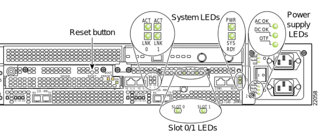
The interfaces are located on the back of the router. The rear panel LEDs shown in Figure 2 provides an overall status of the router operation.
Figure 2 Rear Panel LEDs
Table 1 provides more detailed information conveyed by the LEDs on the rear panel of the router:
18481 Cisco 7100 SERIES AC OK DC OK OTF AC OK DC OK OTF SLOT 0 SLOT 1 5 155 - MM RX RX EN
CEL CAR ALM
TX I 155 - MM CONS FE 0 / 0 FE ACT 0 / 1 AUX 0 2 RX 7140 - 2MM3 RX EN
CEL CAR ALM
TX ACT LNK 0 LNK 1 PWR SYS RDY 22058 System LEDs Slot 0/1 LEDs Power supply LEDs ACT ACT LNK 0 LNK 1 PWR SYS RDY AC OK DC OK OTF SLOT 0 SLOT 1 EN ERROR BOOT RESET SM-ISM Reset button
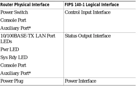
FIPS 140-1 Logical Interfaces
All of these physical interfaces are separated into the logical interfaces from FIPS as described in
Table 2:
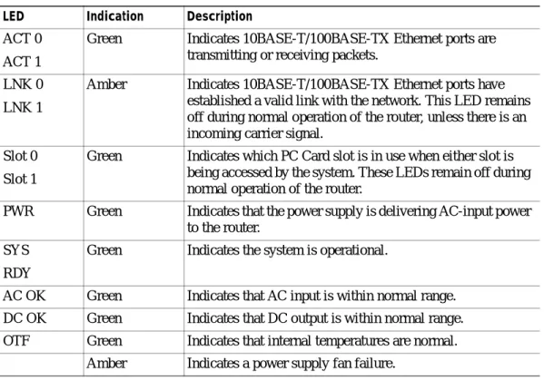
Table 1 Rear Panel LEDs and Descriptions
LED Indication Description
ACT 0 ACT 1
Green Indicates 10BASE-T/100BASE-TX Ethernet ports are transmitting or receiving packets.
LNK 0 LNK 1
Amber Indicates 10BASE-T/100BASE-TX Ethernet ports have established a valid link with the network. This LED remains off during normal operation of the router, unless there is an incoming carrier signal.
Slot 0 Slot 1
Green Indicates which PC Card slot is in use when either slot is being accessed by the system. These LEDs remain off during normal operation of the router.
PWR Green Indicates that the power supply is delivering AC-input power to the router.
SYS RDY
Green Indicates the system is operational.
AC OK Green Indicates that AC input is within normal range. DC OK Green Indicates that DC output is within normal range. OTF Green Indicates that internal temperatures are normal.
Amber Indicates a power supply fan failure.
Table 2 FIPS 140-1 Logical Interfaces
Router Physical Interface FIPS 140-1 Logical Interface
10/100BASE-TX LAN Port Port Adapter Interface Service Module Interface
Console Port Auxiliary Port* PCMCIA Slot*
Data Input Interface
10/100BASE-TX LAN Port Port Adapter Interface Service Module Interface
Console Port Auxiliary Port* PCMCIA Slot*
* Disabled in FIPS mode. See the “Secure Operation of the Cisco 7140 VPN Router” section on page 10 for more information.
The module also has two other RJ-45 connectors for a console terminal for local system access and an auxiliary port for remote system access or dial backup using a modem. Additionally, Cisco 7140 VPN routers have different physical interfaces available in the two fixed WAN ports.
Table 3 gives a description of the Cisco 7140 VPN router series and physical interfaces.
Further information about the different WAN options and their respective status indications (such as LED descriptions) can be found in the “Cisco 7100 Series VPN Router Product Overview” at the following website:
http://www.cisco.com/univercd/cc/td/doc/product/core/7100/hwicg/overegr.htm Power Switch
Console Port Auxiliary Port*
Control Input Interface
10/100BASE-TX LAN Port LEDs
Pwr LED Sys Rdy LED Console Port Auxiliary Port*
Status Output Interface
Power Plug Power Interface
Table 2 FIPS 140-1 Logical Interfaces (continued)
Router Physical Interface FIPS 140-1 Logical Interface
Table 3 Physical Interfaces of Cisco 7140 Routers
Router Description of Physical Interface
Cisco 7140-2T3 Provides two high-speed, synchronous serial ports that support full-duplex operation at T3 (45-Mbps) speeds
Cisco 7140-2E3 Provides two high-speed, synchronous serial ports that support full-duplex operation at E3 (34-Mbps) speeds
Cisco 7140-2AT3 Provides two high-speed, ATM ports that support full-duplex operation at T3 (45-Mbps) speeds
Cisco 7140-2AE3 Provides two high-speed, ATM ports that support full-duplex operation at E3 (34-Mbps) speeds
Cisco 7140-2MM3 Provides two ATM ports that support full-duplex operation at OC-3c/STM1 multimode (155-Mbps) speeds
Cisco 7140-8T Provides eight high-speed, synchronous serial ports that support full-duplex operation at T1 (1.544-Mbps) and E1 (2.048-Mbps) speeds Cisco 7140-2FE Provides two fixed LAN ports —10BASE-T/100BASE-TX autosensing
Ethernet/Fast Ethernet (full and half duplex) equipped with an RJ-45 receptacle
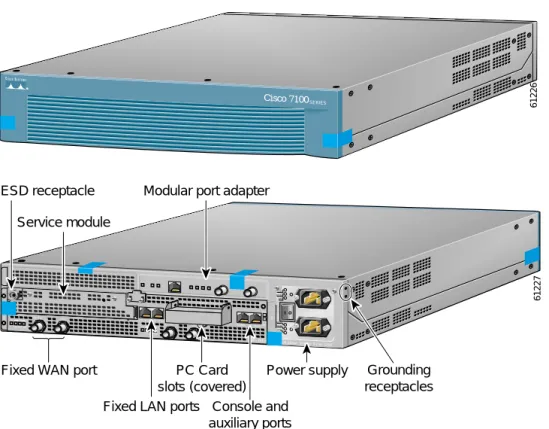
Cisco 7140 VPN Router Slot Numbering
Slots in Cisco 7140 VPN routers are numbered as follows:
• Slot 0 - Fixed LAN (Ethernet) interface
• Slot 1 - Fixed WAN (serial) interface
• Slot 2 - Fixed WAN (serial) interface
• Slot 3 - Not used
• Slot 4 - Modular port adapter
• Slot 5 - Service Module
Figure 3 shows the slots in a Cisco 7140 VPN router.
Figure 3 Cisco 7140 Slot Numbering
Roles and Services
There are two main roles in the router (as required by FIPS 140-1) that operators can assume: crypto officer or administrator role and user role. The administrator of the router assumes the crypto officer role in order to configure and maintain the router using crypto officer services, while the users exercise only the basic user services.
This section also contains the following subsections:
• Cryptographic Officer Services, page 7
• User Services, page 8
Cryptographic Officer Services
During initial configuration of the router, a crypto officer password is defined and all management services are available from this role. The crypto officer connects to the router through the console port through terminal program. A router administrator might assign permission to distribute the crypto officer role to additional accounts, thereby creating additional administrators.
At the highest level, crypto officer services include the following:
• Configure the router: define network interfaces and settings, create command aliases, set the protocols the router will support, enable interfaces and network services, set system date and time, and load authentication information.
SLOT 0 SLOT 1 AC OK DC OK OTF AC OK DC OK OTF 5 155 - MM RX RX EN
CEL CAR ALM
TX I 155 - MM CONS FE 0 / 0 FE ACT 0 / 1 AUX 0 2 RX 7140 - 2MM3 RX EN
CEL CAR ALM
TX ACT LNK 0 LNK 1 PWR SYS RDY EN ERROR BOOT RESET SM-ISM 18499
Slot 1 Slot 0 Slot 2
Slot 4 Slot 5
• Define rules and filters: create packet filters that are applied to user data streams on each interface. Each filter consists of a set of rules, which define a set of packets to permit or deny based on characteristics such as protocol ID, addresses, ports, TCP connection establishment, or packet direction.
• Status functions: view the router configuration, routing tables, and active sessions; view SNMP MIB II statistics, health, temperature, memory status, voltage, and packet statistics; review accounting logs, and view physical interface status.
• Manage the router: log off users, shut down or reload the router, manually back up router
configurations, view complete configurations, set manager user rights, restore router configurations.
• Set encryption/bypass: set up the configuration tables for IP tunneling. Set keys and algorithms to be used for each IP range or allow plaintext packets to be set from specified IP addresses.
• Change port adapters: insert and remove adapters in port adapter slots as described in the “Initial
Setup” section on page 10.
User Services
A user enters the system by accessing the console port with a terminal program. The IOS prompts the user for their password. If it matches the plaintext password stored in IOS memory, the user is allowed entry to the IOS executive program. At the highest level, user services include the following:
• Status Functions: view state of interfaces, state of layer 2 protocols, version of IOS currently running
• Network Functions: connect to other network devices through outgoing telnet or PPP and initiate diagnostic network services (for example, ping or mtrace)
• Terminal Functions: adjust the terminal session (that is, lock the terminal and adjust flow control)
• Directory Services: display directory of files kept in flash memory
Physical Security
The router is entirely encased by a thick steel chassis. The back of the router provides one port adapter slot, one service module slot, on-board LAN connectors, PCMCIA slots, Console/Auxiliary connectors, the power cable connections, and the power switch.
Once the router has been configured to meet FIPS 140-1 Level 2 requirements, the router cannot be accessed without signs of tampering. To seal the system, apply serialized tamper-evidence labels as follows:
• Clean the cover of any grease, dirt, or oil before applying the tamper evidence labels. Alcohol-based cleaning pads are recommended for this purpose. The ambient air must be above 10C, otherwise the labels may not properly cure.
• The tamper evidence label should be placed so that the one half of the tamper evidence label covers the front panel of the router and the other half covers the enclosure (both the module cover and enclosure).
• The tamper evidence label should be placed over the cover for the Flash PC Card slots (next to the screw on the underside) so that any attempt to open the Flash PC Card cover will show tamper evidence.
• The tamper evidence label should be placed so that the one half of the label covers the module and the other half covers the service module slot.
• The tamper evidence label should be placed so that the one half of the label covers the enclosure and the other half covers the port adapter slot.
• The tamper evidence label should be placed so that the one half of the label covers the enclosure and the other half covers the slot cover to the left of the port adapter (Slot 3).
• The labels completely cure within five minutes.
Figure 4 shows the tamper evidence label placements.
Figure 4 Tamper Evidence Label Placement
The tamper evidence seals are produced from a special thin gauge vinyl with self-adhesive backing. Any attempt to remove port adapters or service modules will damage the tamper evidence seals or the painted surface and metal of the module cover. Since the tamper evidence labels have nonrepeated serial numbers, the labels can be inspected for damage and compared against the applied serial numbers to verify that the module has not been tampered with. Tamper evidence labels can also be inspected for signs of tampering, which include the following: curled corners, bubbling, crinkling, rips, tears, and slices. The word “Opened” can appear if the label was peeled back.
Note If possible, try to place the tamper evidence labels so that few of the ventilation holes are covered.
Cryptographic Key Management
The router securely administers both cryptographic keys and other critical security parameters such as passwords. The tamper evidence seals provide physical protection for all keys. Keys are also password protected and can be zeroized by the crypto officer. Keys are exchanged manually and entered
61226 Cisco 7100 SERIES AC OK DC OK OTF AC OK DC OK OTF RX TX E3 RX 5 TX E3 RX EN
CEL CAR ALM
I CONS FE 0 / 0FE ACT 0 / 1 AUX 0 2
7140 - 2AE3 100-240Vac 50/60Hz 5-2.5A 525W
RX EN
CEL CAR ALM ACT LNK 0 LNK 1 PWR SYS RDY SLOT 0 SLOT 1 61227 Power supply PC Card slots (covered) Fixed LAN ports Console and
auxiliary ports Fixed WAN port
Modular port adapter Service module
ESD receptacle
Grounding receptacles
electronically via manual key exchange or Internet Key Exchange (IKE). The Cisco 7140 router supports the following FIPS-approved algorithms: DES, 3DES, and SHA-1. These algorithms received
certification numbers 74, 17, and 26 respectively.
Self-Tests
In order to prevent any secure data from being released, it is important to test the cryptographic components of a security module to insure all components are functioning correctly. The router includes an array of self-tests that are run during startup and periodically during operations. The self-tests run at power-up includes a cryptographic known answer test (KAT) on the FIPS-approved cryptographic algorithms (DES, 3DES), on the message digest (SHA-1), and on the Diffie-Hellman algorithm. Also performed at startup are a software integrity test using an EDC and a set of Statistical Random Number Generator (RNG) tests. The following tests are also run periodically or conditionally: a bypass mode test performed conditionally prior to executing IPSec, a software load test for upgrades, and the continuous random number generator test. If any of these self-tests fail, the router transitions into an error state. Within the error state, all secure data transmission is halted and the router outputs status information indicating the failure.
Secure Operation of the Cisco 7140 VPN Router
Cisco 7140 VPN routers meet all the Level 2 requirements for FIPS 140-1. Follow the setting instructions provided below to place the module in FIPS mode. Operating this router without
maintaining the following settings will remove the module from the FIPS approved mode of operation.
Initial Setup
• The crypto officer must apply tamper evidence labels as described in the “Physical Security” section in this document. The crypto officer must securely store tamper evidence labels before use, and any tamper evidence labels not used should also be stored securely.
• Only a crypto officer can add and remove port adapters. When removing the tamper evidence label, the crypto officer should remove the entire label from the router and clean the cover of any grease, dirt, or oil with an alcohol-based cleaning pad. The crypto officer must reapply tamper evidence labels on the router as described in the “Physical Security” section in this document.
System Initialization and Configuration
• The crypto officer must perform the initial configuration. The IOS version shipped with the router, version 12.1(9)E, is the only allowable image. No other image can be loaded.
• The value of the boot field must be 0x0101 (the factory default). This setting disables the break from the console to the ROM monitor and automatically boots the IOS image. From the configure
terminal command line, the crypto officer enters the following syntax: config-register 0x0101
• The crypto officer must create the “enable” password for the crypto officer role. The password must be at least eight characters and is entered when the crypto officer first engages the enable command. The crypto officer enters the following syntax at the “#” prompt:
enable secret [password]
• The crypto officer must always assign passwords (of at least eight characters) to users. Identification and authentication of the console port is required for Users. From the configure terminal command line, the crypto officer enters the following syntax:
line con 0
password [password] login local
• The crypto officer shall only assign users to a privilege level 1 (the default).
• The crypto officer shall not assign a command to any privilege level other than its default.
• The Flash PC Card slot is not configured in FIPS mode. Its use is restricted via tamper evidence labels (see the “Physical Security” section in this document).
Non FIPS-Approved Algorithms
• The following algorithms are not FIPS approved and should be disabled:
– RSA for encryption
– MD-5 for signing
– AH-SHA-HMAC
– ESP-SHA-HMAC
– HMAC SHA-1
Protocols
• The following network services affect the security data items and must not be configured: NTP, TACACS+, RADIUS, Kerberos.
• SNMP v3 over a secure IPSec tunnel can be employed for authenticated, secure SNMP Gets and Sets. Since SNMP v2C uses community strings for authentication, only gets are allowed under SNMP v2C.
Remote Access
• Auxiliary terminal services must be disabled, except for the console. The following configuration disables login services on the auxiliary console line.
line aux 0 no exec
• Telnet access to the module is only allowed via a secure IPSec tunnel between the remote system and the module. The Crypto officer must configure the module so that any remote connections via telnet are secured through IPSec.
Obtaining Documentation
The following sections provide sources for obtaining documentation from Cisco Systems.
World Wide Web
You can access the most current Cisco documentation on the World Wide Web at the following sites:
• http://www.cisco.com
• http://www-china.cisco.com
• http://www-europe.cisco.com
Documentation CD-ROM
Cisco documentation and additional literature are available in a CD-ROM package, which ships with your product. The Documentation CD-ROM is updated monthlyand can be more current than printed documentation. The CD-ROM package is available as a single unit or as an annual subscription.
Ordering Documentation
Cisco documentation is available in the following ways:
• Registered Cisco Direct Customers can order Cisco Product documentation from the Networking Products MarketPlace:
http://www.cisco.com/cgi-bin/order/order_root.pl
• Registered Cisco.com users can order the Documentation CD-ROM through the online Subscription Store:
http://www.cisco.com/go/subscription
• Nonregistered Cisco.com users can order documentation through a local account representative by calling Cisco corporate headquarters (California, USA) at 408 526-7208 or, in North America, by calling 800 553-NETS(6387).
Documentation Feedback
If you are reading Cisco product documentation on the World Wide Web, you can submit technical comments electronically. Click Feedback in the toolbar and select Documentation. After you complete the form, click Submit to send it to Cisco.
To submit your comments by mail, use the response card behind the front cover of your document, or write to the following address:
Attn Document Resource Connection Cisco Systems, Inc.
170 West Tasman Drive San Jose, CA 95134-9883 We appreciate your comments.
Obtaining Technical Assistance
Cisco provides Cisco.com as a starting point for all technical assistance. Customers and partners can obtain documentation, troubleshooting tips, and sample configurations from online tools. For Cisco.com registered users, additional troubleshooting tools are available from the TAC website.
Cisco.com
Cisco.com is the foundation of a suite of interactive, networked services that provides immediate, open access to Cisco information and resources at anytime, from anywhere in the world. This highly integrated Internet application is a powerful, easy-to-use tool for doing business with Cisco.
Cisco.com provides a broad range of features and services to help customers and partners streamline business processes and improve productivity. Through Cisco.com, you can find information about Cisco and our networking solutions, services, and programs. In addition, you can resolve technical issues with online technical support, download and test software packages, and order Cisco learning materials and merchandise. Valuable online skill assessment, training, and certification programs are also available. Customers and partners can self-register on Cisco.com to obtain additional personalized information and services. Registered users can order products, check on the status of an order, access technical support, and view benefits specific to their relationships with Cisco.
To access Cisco.com, go to the following website:
http://www.cisco.com
Technical Assistance Center
The Cisco TAC website is available to all customers who need technical assistance with a Cisco product or technology that is under warranty or covered by a maintenance contract.
Contacting TAC by Using the Cisco TAC Website
If you have a priority level 3 (P3) or priority level 4 (P4) problem, contact TAC by going to the TAC website:
P3 and P4 level problems are defined as follows:
• P3—Your network performance is degraded. Network functionality is noticeably impaired, but most business operations continue.
• P4—You need information or assistance on Cisco product capabilities, product installation, or basic product configuration.
In each of the above cases, use the Cisco TAC website to quickly find answers to your questions. To register for Cisco.com, go to the following website:
http://www.cisco.com/register/
If you cannot resolve your technical issue by using the TAC online resources, Cisco.com registered users can open a case online by using the TAC Case Open tool at the following website:
http://www.cisco.com/tac/caseopen
Contacting TAC by Telephone
If you have a priority level 1 (P1) or priority level 2 (P2) problem, contact TAC by telephone and immediately open a case. To obtain a directory of toll-free numbers for your country, go to the following website:
http://www.cisco.com/warp/public/687/Directory/DirTAC.shtml
P1 and P2 level problems are defined as follows:
• P1—Your production network is down, causing a critical impact to business operations if service is not restored quickly. No workaround is available.
• P2—Your production network is severely degraded, affecting significant aspects of your business operations. No workaround is available.
AccessPath, AtmDirector, Browse with Me, CCIP, CCSI, CD-PAC, CiscoLink, the Cisco Powered Network logo, Cisco Systems Networking Academy, the Cisco Systems Networking Academy logo, Fast Step, Follow Me Browsing, FormShare, FrameShare, GigaStack, IGX, Internet Quotient, IP/VC, iQ Breakthrough, iQ Expertise, iQ FastTrack, the iQ Logo, iQ Net Readiness Scorecard, MGX, the Networkers logo, Packet, RateMUX, ScriptBuilder, ScriptShare, SlideCast, SMARTnet, TransPath, Unity, Voice LAN, Wavelength Router, and WebViewer are trademarks of Cisco Systems, Inc.; Changing the Way We Work, Live, Play, and Learn, Discover All That’s Possible, and Empowering the Internet Generation, are service marks of Cisco Systems, Inc.; and Aironet, ASIST, BPX, Catalyst, CCDA, CCDP, CCIE, CCNA, CCNP, Cisco, the Cisco Certified Internetwork Expert logo, Cisco IOS, the Cisco IOS logo, Cisco Press, Cisco Systems, Cisco Systems Capital, the Cisco Systems logo, Enterprise/Solver, EtherChannel, EtherSwitch, FastHub, FastSwitch, IOS, IP/TV, LightStream, MICA, Network Registrar, PIX, Post-Routing, Pre-Routing, Registrar, StrataView Plus, Stratm, SwitchProbe, TeleRouter, and VCO are registered trademarks of Cisco Systems, Inc. and/or its affiliates in the U.S. and certain other countries.
By printing or making a copy of this document, the user agrees to use this information for product evaluation purposes only. Sale of this information in whole or in part is not authorized by Cisco Systems.
All other trademarks mentioned in this document or Web site are the property of their respective owners. The use of the word partner does not imply a partnership relationship between Cisco and any other company. (0110R)
Cisco 7140 VPN Router Security Policy
Copyright © 2001, Cisco Systems, Inc. All rights reserved.