An Overview of Urban
Stormwater-Management Practices in Miami-Dade
County, Florida
By David A. Chin
U.S. Department of the Interior
U.S. Geological Survey
Prepared in cooperation with the
SOUTH FLORIDA WATER MANAGEMENT DISTRICT
Gale A. Norton, Secretary
U.S. Geological Survey
Charles G. Groat, Director
U.S. Geological Survey, Reston, Virginia: 2004
For sale by U.S. Geological Survey, Information Services Box 25286, Denver Federal CenterDenver, CO 80225
For more information about the USGS and its products:
Telephone: 1-888-ASK-USGS
World Wide Web: http://www.usgs.gov/
Any use of trade, product, or firm names in this publication is for descriptive purposes only and
does not imply endorsement by the U.S. Government.
Although this report is in the public domain, permission must be secured from the individual
copyright owners to reproduce any copyrighted materials contained within this report.
Suggested citation:
Chin, D.A., 2004, An Overview of Urban Stormwater-Management Practices in Miami-Dade
County, Florida: U.S. Geological Survey Open-File Report 2004-1346, 17 p.
iii
Contents
Abstract . . . 1
Introduction. . . 1
Relevance and Benefits . . . 1
Acknowledgments . . . 2
Urban Stormwater-Management Practices . . . 2
Overview of Agency Stormwater-Management Requirements . . . 2
Miami-Dade Department of Environmental Resources Management . . . 2
Roadways. . . 2
Community Stormwater Management . . . 2
South Florida Water Management District . . . 5
Water-Quantity Criteria . . . 5
Water-Quality Criteria . . . 7
Florida Department of Transportation . . . 9
Open Channels . . . . 10
Storm Drains . . . 11
Stormwater Management. . . 12
Design of Exfiltration Trenches . . . 12
Agency Design Methodologies. . . 12
South Florida Water Management District . . . 12
Miami-Dade Department of Environmental Resources Management. . . 13
Florida Department of Transportation. . . 14
Alternative Exfiltration Trench Design . . . 14
Summary . . . 16
References Cited . . . 17
Figures
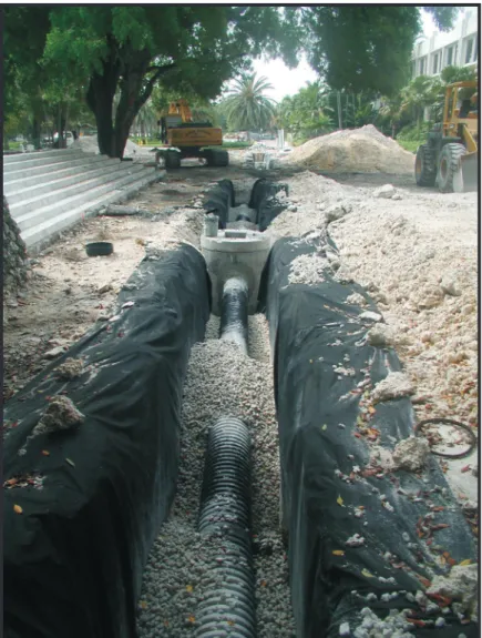
1. Photograph showing exfiltration trench under construction . . . 42. Map showing location of major roads and canals in Miami-Dade County, Florida. . . 5
3. Hyetograph showing rainfall distribution for a hypothetical 3-day storm. . . 6
4. Map showing Florida Department of Transportation rainfall zones. . . 9
5. Comparison of Miami-Dade Department of Environmental Resources Management and Florida Department of Transportation intensity duration frequency curves for return periods of 5, 10, and 25 years . . . 10
Tables
1. Miami-Dade Department of Environmental Resources Management design
storm frequenciesand flood limits . . . 3 2. Data points for a normalized South Florida Water Management District
3-day hyetograph . . . 7-8
Conversion Factors and Vertical Datum
Vertical coordinate information is referenced to the North American Vertical Datum of
1988 (NAVD 88); horizontal coordinate information is referenced to the North American
Datum of 1927 (NAD 27), unless otherwise noted.
Acronyms and Abbreviations
Multiply By To Obtain
inch (in.) 2.54 centimeter (cm)
inch per hour (in/hr) 2.54 centimeter per hour (cm/hr) inch per day (in/d) 2.54 centimeter per day (cm/d)
foot (ft) 0.3048 meter (m) square foot (ft2) 0.09290 square meter (m2) foot per second (ft/s) 0.3048 meter per second (m/s)
foot per second squared (ft/s2) 0.3048 meter per second squared (m/s2) square foot per second (ft2/s) 0.09290 square meter per second (m2/s) cubic foot per second per square foot
per foot (ft3/s/ft2/ft)
1.000 cubic meter per second per square meter per meter (m3/s/m2/m) acre 0.004047 square meter (m2)
DERM Miami-Dade Department of Environmental Resources Management
FDOT Florida Department of Transportation FEMA Federal Emergency Management Agency
HGL Hydraulic grade line IDF Intensity duration frequency mph mile per hour
NPDES National Pollutant Discharge Elimination System ppm part per million
SFWMD South Florida Water Management District USGS U.S. Geological Survey
An Overview of Urban Stormwater-Management
Practices in Miami-Dade County, Florida
By David A. Chin
Abstract
Agencies with jurisdiction over stormwater-management systems in Dade County, Florida, include the Miami-Dade Department of Environmental Resources Management (DERM), South Florida Water Management District (SFWMD), and Florida Department of Transportation (FDOT). These agen-cies are primarily concerned with minor drainage systems that handle runoff from storms with return periods of 10 years or less (DERM), major drainage systems that handle runoff from storms with return periods of 25 years or more (SFWMD), and runoff from major roadways (FDOT). All drainage regulations require retention of at least a specified water-quality volume (defined volume of surface runoff), typically the first inch of runoff. The DERM and FDOT intensity duration frequency (IDF) curves used as a basis for design are similar but different, with differences particularly apparent for short-duration storms. The SFWMD 25-year 3-day storm incorporates an IDF curve that is substantially different from both the IDF curves of DERM and FDOT. A DERM methodology for designing closed exfiltration systems is applicable to storms of 1-hour duration, but is not applicable to all storms with a given T-year return period. A trench design that is applicable to all storms with a given
T-year return period is presented as an alternative approach.
Introduction
Stormwater management in Miami-Dade County, Florida, is regulated by several governmental agencies, primarily the Miami-Dade Department of Environmental Resources Manage-ment (DERM), the South Florida Water ManageManage-ment District (SFWMD), and the Florida Department of Transportation (FDOT). These agencies address the quantities of surface runoff that must be handled by drainage systems, and the amount of onsite treatment that must be provided.
Stormwater-management systems include minor and major drainage systems. Minor drainage systems typically consist of stormwater inlets to subsurface systems that handle runoff from design storms with return periods of 10 years or less, whereas major drainage systems typically include the above-ground pathways that handle runoff from storms with greater return periods. A clear understanding of the role and function of stormwater-management systems and the regulatory environment in which these systems are designed provides for realistic expectations of their performance during periods of heavy rainfall.
The purposes of this report are to: (1) present an overview of the State and local regulations governing the design of storm-water management systems in Miami-Dade County, (2) describe the types of stormwater-management systems that are com-monly used, and (3) present an approach for designing closed exfiltration trench systems to accept runoff from all storms with a given T-year return period. Agency documents should be con-sulted for detailed design guidance. This report is the result of a cooperative effort between the U.S. Geological Survey (USGS) and SFWMD.
Relevance and Benefits
This report is intended to assist engineers, scientists, regulators, and the general public in understanding the function and performance of stormwater-management systems in Miami-Dade County, Florida. The Federal Government also has a stake in the effectiveness of stormwater management systems. The prevention of flooding and associated property losses are a concern of the Federal Emergency Management Agency (FEMA), and the quality of stormwater runoff discharged to surface waters in Miami-Dade County is covered by National Pollutant Discharge Elimination System (NPDES) permits.
Acknowledgments
The author acknowledges the contributions, advice, and technical reviews provided by Manny Tobon (DERM), Tony Waterhouse (SFWMD), Ricardo Salazar (FDOT), and USGS employees Eric Swain, Barbara Howie, Kathleen Hammett, and Arturo Torres. Rhonda Howard (USGS) and Kimberly Swidarski (USGS) made essential contributions to the produc-tion of this report.
Urban Stormwater-Management Practices
Flooding occurs when the capacity of the drainage system is exceeded and, regardless of the drainage system used, the probability of flooding in any area is never zero. The reliability of drainage systems to prevent flooding is based on the return period of the design rainfall event. The probability, P, that the capacity of a drainage system is exceeded in any year is related to the return period, T, of the design rainfall event by the relation:P 1
T
---= . (1)
This equation is based on the common assumptions that the peak runoff with return period T is generated by a rainfall event with return period T. Deviations from this assumption are caused by varying antecedent conditions.
Regulatory codes in Miami-Dade County, Florida, gener-ally require that minor drainage systems in public areas be designed for storms with return periods on the order of 5 to 10 years; therefore, local flooding in these areas should not be expected to occur more frequently than once every 5 to 10 years on average. This means that there is a 10 to 20 percent chance of flooding in these areas in any given year.
Stormwater-management systems can be broadly classi-fied as either community systems (managing stormwater runoff from subdivisions and individual properties) or roadway drain-age systems (controlling the runoff from roadways and the adjacent rights-of-way). Community drainage systems are seldom combined with drainage systems of major roadways.
Overview of Agency Stormwater-Management
Requirements
Agencies with jurisdiction over stormwater-management systems in Miami-Dade County include DERM, SFWMD, and FDOT. The stormwater-management requirements of these agencies are presented in the subsequent sections.
Miami-Dade Department of Environmental Resources
Management
All land developed in Miami-Dade County is required to be above the Flood Criteria Elevations (Miami-Dade Depart-ment of EnvironDepart-mental Resources ManageDepart-ment, 1982). At any given location, the Flood Criteria Elevation is defined as the higher of: (1) the 10-year 1-day ground-water elevation; and (2) the 5-year 1-week ground-water elevation plus 18 in. (Board of County Commissioners of Dade County, 1959). The primary objectives of establishing these flood-criteria elevations are to limit ground-surface flooding to return periods greater than 10 years, and to limit septic-tank failure to return periods greater than 5 years. The septic-tank criterion incorpo-rates the requirement that septic-tank drain tiles are required to be at least 18 in. below the ground surface. Flood Criteria Elevations have not been reevaluated for over 20 years, and thus, may not reflect current water-management practices.
Roadways
All roadways in Miami-Dade County are required to have a minimum longitudinal grade of 0.2 percent for drainage purposes, and the design return periods for roadway drainage systems depend on the type of roadway, as presented in table 1. These requirements indicate that two-lane roads in residential areas must accommodate runoff from all storms with a 5-year return period with maximum encroachment up to the crown of the roadway. Four-lane arterial roads in density, high-traffic areas are designed to accommodate storms with a 10-year return period with maximum encroachment to the outer edge of the traffic lanes (Miami-Dade Department of Environ-mental Resource Management, 1982).
Community Stormwater Management
Design storms with 5-year return periods are required in the design of residential and commercial stormwater-manage-ment systems, and full onsite retention of design storm runoff is required if at all possible (Miami-Dade Department of Environ-mental Resources Management, 1980). The implication of this requirement is that the stormwater-management system must be capable of accepting runoff from 5-year storms of any duration. Five-year storms with a 1-hour duration typically are used in assessing the capacity of onsite drainage structures, such as exfiltration trenches. A limitation of this approach is that the maximum runoff rate does not necessarily result from a 5-year 1-hour storm; therefore, a drainage structure designed for a 5-year 1-hour storm could fail more frequently than every 5 years. A 5-year 1-hour storm in Miami-Dade County produces about 3.3 in. of rainfall. Assuming that a typical runoff coefficient of 0.7 yields about 2.3 in. of runoff for a 1-hour storm, full onsite retention would require a stormwater-management system to store and infiltrate at least 2.3 in. of runoff in 1 hour.
Urban Stormwater-Management Practices 3
In many instances, environmental conditions do not permit full onsite retention of the design runoff due to poor soil infiltration, and in such instances, Miami-Dade County encour-ages retention of at least the first inch of runoff. Because most contaminants are considered to be contained in the first inch of runoff, this rule is intended to at least meet the water-quality objectives of stormwater-management systems, even if the water-quantity objectives cannot be met. Supplementary systems, such as emergency overflow pipes that allow excess water to be discharged into off-site surface-water bodies, are used to provide flood protection when the capacity of the onsite retention system is exceeded. Typical onsite retention systems include exfiltration trenches, swales, greenways, and lakes. In cases where onsite lakes are used for onsite retention or deten-tion (prior to off-site discharge), a commonly overlooked and important finding reported by Gregg (1984) is that these lakes tend to fill more than expected from surface runoff alone because the surrounding aquifer also recharges the lake in response to rainfall. The lakes, therefore, rise higher and recede more slowly than expected. This effect may reduce the avail-able storage for closely spaced rainfall events.
Conventional urban drainage systems are designed to accommodate the peak runoff that results from a storm of a given return period. The rational method is the most widely used method for calculating the peak runoff, Qp, which is related to the runoff coefficient, C, average rainfall intensity, i, and catchment area, A, by the relation:
Qp = CiA, (2)
where the average rainfall intensity, i, is related to storm dura-tion by the local intensity duradura-tion frequency (IDF) curve. The IDF curve for Miami-Dade County can be approximated by:
i 308.5
48.6T–0.11+t(0.5895+T–0.67)
---= , (3)
where i is the average intensity in inches per hour, T is the return period in years, and t is the rainfall duration in minutes (Miami-Dade Department of Environmental Resources Management, 1980; Salazar and others, 1991). To maximize the peak catchment runoff for a given return period, the storm duration typically is equal to the time of concentration of the catchment area. The time of concentration, tc, typically is calculated using the kinematic-wave equation:
tc 0.93(nL)0.6
i0.4So0.3
---= , (4)
where tc is in minutes, n is the Manning roughness coefficient,
L is the overland-flow length in feet, i is the rainfall intensity in inches per hour, and So is the average ground slope (Miami-Dade Public Works Department, 2001b).
The off-site disposal of stormwater runoff directly (with-out pretreatment) into open bodies of water, such as canals, is commonly referred to as positive drainage. In Miami-Dade County, positive drainage is the least acceptable form of storm-water management (Miami-Dade Department of Environmental Resources Management, 1980). Although positive drainage is not totally prohibited, alternative systems, such as onsite tion systems, generally must be considered first. Onsite reten-tion systems generally include:
• surface infiltration through grassed swales,
• underground (seepage) disposal through exfiltration trenches (French drains) and slab-covered trenches, • retention ponds,
• disposal by drainage wells, and • any combination of the above systems.
Stormwater-management systems generally are designed for both quantity and quality control. In instances where more than one type of stormwater-management system can be used, the
Table 1. Miami-Dade Department of Environmental Resources Management design storm frequencies and flood limits.
[From Miami-Dade Department of Environmental Resource Management, 1982]
Type of area Rainfall frequency
(return period) Flood limit
Residential and commercial areas 5 years To crown of street or to within 15 feet of a dwelling or other occupied building, whichever is lower Two-lane roads in residential areas 5 years, except 10 years for a bridge or
culvert in the canal system
To crown of street
Four-lane roads in high-density, high-traffic areas
10 years To outer edge of traffic lanes
Private parking lots and similar paved areas
system that affords the most filtration is the most desirable (Miami-Dade Department of Environmental Resources Management, 1980).
Surface-infiltration systems, such as grassed swales, atten-uate more pollutants than any other onsite retention system (Miami-Dade Department of Environmental Resources Management, 1980). Grassed swales can be linear (such as a channel) or circular (such as a basin). Circular swales are clas-sified as dry retention systems. When grassed swales are used for drainage, runoff is channeled into these grassed areas where the water either partially or totally infiltrates into the soil. Although surface-infiltration systems are most desirable from a water-quality perspective, the limitation of surface-infiltration rates usually makes them least desirable from a water-quantity perspective, so backup seepage systems usually are provided.
Seepage systems represent the bulk of the stormwater-management systems used in Miami-Dade County, and include exfiltration trenches (also known as French drains), seepage
trenches, and soakage pits. Seepage systems are designed to perform a water-treatment function by onsite retention of at least the first inch of runoff, and in some instances, they accommodate the entire design runoff. Unlike surface infiltration systems, seep-age systems consist of underground structures that rely on the outward dispersal of stormwater to the ground water. A typical trench system (fig. 1) consists of an inlet structure, which leads to a horizontal perforated pipe surrounded by gravel.
The DERM criteria require that trench systems be designed so that the volume of storage and exfiltration during 1 hour is equal to the design runoff volume. The term “seepage capacity" commonly used by engineers refers to the total volume of water that can be stored in and exfiltrated from the trench in 1 hour. Seepage capacities generally are derived from the results of open-hole tests (Cullum, 1984) performed at the trench location. The standard detail for exfiltration trenches in Miami-Dade County is outlined by the Miami-Dade Public Works Department (2001a). Typically, an exfiltration trench is
15 ft deep, 3.5 ft wide, filled with ballast rock, and contains a 15-in.-diameter (minimum) perfo-rated pipe, with the perfoperfo-rated-pipe invert at or above the average October water-table eleva-tion. Because of the need to provide 2-ft cover over the perforated pipe, however, DERM in many instances allows the pipe to be a maximum of 6 in. into the water table. The potential for exfiltration trenches to clog and perform poorly is generally a concern (Whalen and Cullum, 1988).
Other stormwater-management systems commonly used in southern Florida are retention ponds and drainage wells. Retention ponds are a type of seepage system that consists of open bodies of water. Retention ponds are classified as wet retention systems, and control water quality by removing nutrients through plant uptake before the runoff enters the ground-water system. Drainage wells are open-ended vertical pipes that discharge stormwater into a portion of the surfi-cial aquifer system containing native ground water with a minimum chloride concentration of 1,500 ppm. Drainage wells must comply with the requirements for Class V wells as stipulated in chapter 17-8 of the Florida Statutes (Miami-Dade Department of Environmental Resources Man-agement, 1980). Drainage wells are installed pri-marily in coastal areas having high water tables, typically in areas abutting Biscayne Bay and the Atlantic Ocean (fig. 2).
Urban Stormwater-Management Practices 5
South Florida Water Management District
Environmental resource permits are required for the construction and operation of surface-water management systems within the SFWMD, including Miami-Dade County. There are three types of environmental resource permits: conceptual, individual, and general permits. Conceptual permits are given for projects that are to be developed in phases, and do not authorize the construction of surface-water management systems. Individual permits are issued for the construction of specific surface-water management systems. General permits are issued for activities below the thresholds
established for individual permits. Most stormwater-manage-ment systems serving areas larger than 100 acres require indi-vidual permits; otherwise they are covered under general permits. Stormwater-management systems are required to meet State water-quantity and water-quality criteria as specified by the SFWMD.
Water-Quantity Criteria
The South Florida Water Management District (2002) water-quantity requirements for stormwater-management systems must be met in addition to any other local municipal requirements. The SFWMD water-quantity requirements are as follows:
0 5 10 MILES
0 5 10 KILOMETERS
80°45´ 80°30´ 80°15´
26°00´
25°15´ 25°30´ 25°45´
Homestead
27
Tamiami Canal (C-4)
826
1
27
836
874
95
Snapper Creek Canal
Hialeah
Mowry Canal
Canal 111
Canal Canal Canal
Creek Black
Model Land Model Land
Military Canal
C-100C
L-31E Canal
Cutler Ridge
Princeton
Kendall
Drain Canal Cutler
Snake Creek Canal
Biscayne Canal
Arch Creek
FLORIDAS
TURNPIKE
North Miami
41
BROWARD COUNTY MIAMI-DADE COUNTY
MIAMI-DADE
COUNTY
MONROE
COUNTY
Little River Canal
Levee 67A
Levee 67C
Levee
67
WATER CONSERVATION
AREA 3A
WATER CONSERVATION
AREA 3B
EVERGLADES NATIONAL
PARK
Levee 29
Levee
30
Levee
31N
ATLANTIC OCEAN
BARNES SOUND
MIAMI CANAL
C-4
CoralGables
Canal
C-100A
Miami
Comfort Canal
C-100B
BISCA YNE B
AY
Miami-Dade County
• Off-site discharge—The off-site discharge rate is limited to rates that do not cause adverse effects to existing off-site properties, historic-discharge rates, rates determined in previous District permit actions, or other rates specified by the District.
• Design storm—Unless otherwise specified by previ-ous District permits or criteria, a storm event having a 3-day duration and 25-year return frequency must be used in computing off-site discharge rates. In instances where there is no off-site discharge, adequate above-ground onsite storage must be available to accommo-date the 25-year 3-day storm.
• Flood protection of building floors—Building floors must be at or above the 100-year flood elevations as determined from the most appropriate information, including Federal Flood Insurance Rate Maps. Both tidal flooding and the 100-year 3-day storm event are considered in determining elevations.
• Flood protection of roads and parking lots—In instances where criteria are not specified by local government with jurisdiction, the design criteria used for drainage and flood protection are: 5-year 1-day storm for road centerlines, and 5-year 1-hour storm for parking lots served by exfiltration systems.
• Floodplain encroachment—No net encroachment is allowed into the floodplain between the average wet-season water table and that encompassed by the 100-year event, which will adversely affect the existing rights of others.
• Historic basin storage—Provision must be made to replace or otherwise mitigate the loss of historic basin storage provided by the project site.
• Off-site lands—Onsite works, such as swales and dikes, must be used to allow the passage of drainage from off-site areas to downstream areas.
• Minimum drainage—The minimum drainage require-ments apply to both residential projects and commer-cial/industrial developments:
• Residential projects must have systems with the calculated ability to discharge by surface flow or subsurface percolation at least 0.375 in/d during or subsequent to the storm of the allowable discharge frequency and duration. As a result, lowering of the management elevations within the water-management system to the maximum depth compat-ible with environmental protection or other constraints will occur in 12 days or less.
• Commercial and industrial developments must have a water-quality system for 1 in. of runoff detention or 0.5 in. of runoff retention. The latter case is a minimum requirement for projects to be subdivided for sale, and individual sites within the development must provide a remaining detention equal to 2.5 in. times percent impervious minus 1 in.
Most drainage designs are based on a SFWMD-specified rainfall distribution (hyetograph) for a hypothetical 3-day storm. This rainfall hyetograph is shown in figure 3, and the data used to plot this curve are given in table 2. The first 2.5 days of
0 12 24 36 48 60 72
TIME, IN HOURS
0 0.2 0.4 0.6 0.8 1.0 1.2 1.4
P = Precipitation depth
P = Total 24-hour rainfall depth24
P/P
24
EXPLANATION
NORMALIZED SFWMD 3-DAY HYETOGRAPH
Figure 3. Rainfall distribution for a hypothetical 3-day storm. Points on curve are given in table 2. SFWMD is South Florida Water Management District.
Urban Stormwater-Management Practices 7
this design event contains uniform, relatively light rainfall, and the most intense rainfall occurs midway through the third day. If this design rainfall were to actually occur, then in some instances this would be the only time that pervious areas would contribute to runoff.
Water-Quality Criteria
The SFWMD requirements for the water-quality compo-nents of stormwater-management systems must be met in Miami-Dade County. The requirements for discharge water quality, retention/detention criteria, underground exfiltration systems, and impervious areas are summarized herein.
• Discharge water quality—Off-site discharges must meet State water-quality standards.
• Retention/detention criteria—There are volumetric requirements and land-use and coverage criteria for this water-quality component. These methodologies are described as follows:
Volumetric requirements
I. Retention, detention, or both retention and detention in the overall system, including swales, lakes, canals, greenways, must be provided to meet one of the three following criteria (or equivalent combination):
A. Wet detention volume provided for the first inch of runoff from the developed project, or the total runoff of 2.5 in. times the percentage of imperviousness, whichever is greater.
B. Dry detention volume provided equal to 75 percent of the above amounts computed for wet detention. C. Retention volume provided for 50 percent of the
above amount computed for wet detention. II. Systems with inlets in grassed areas are credited with up
to 0.2 in. of the required wet detention amount for the contributing areas. Full credit is based on the ratio of 10:1 impervious area (paved or building area) to pervious area (that is, the grassed area) with proportionately less credit granted for greater ratios.
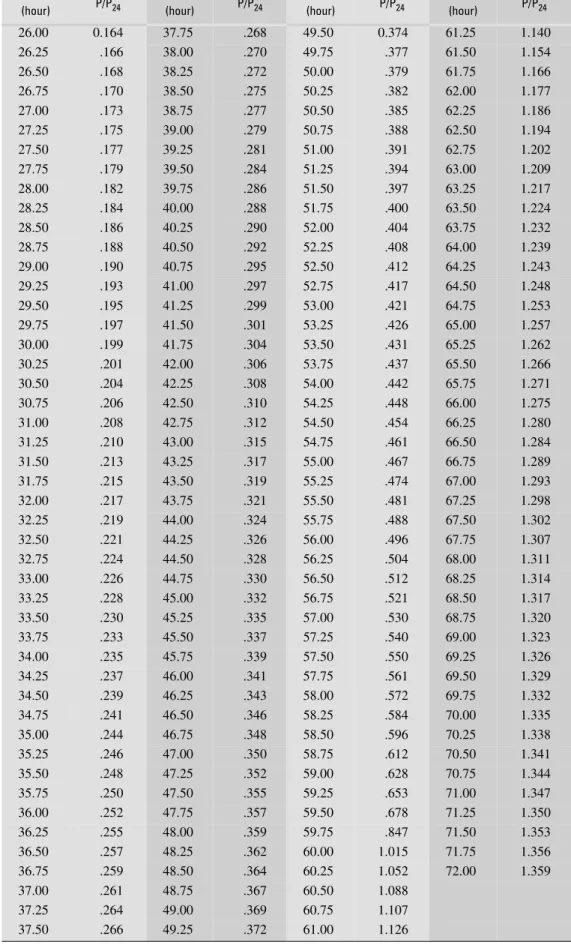
Table 2. Data points for the normalized South Florida Water Management District 3-day hyetograph.
[Data points apply to curve shown in fig. 3. P is precipitation depth; P24 is total 24-hour rainfall depth]
Time
(hour) P/P24
Time
(hour) P/P24
Time
(hour) P/P24
Time
(hour) P/P24
0.00 0.000 6.50 0.040 13.00 0.079 19.50 0.119
0.25 .002 6.75 .041 13.25 .081 19.75 .120
0.50 .003 7.00 .043 13.50 .082 20.00 .122
0.75 .005 7.25 .044 13.75 .084 20.25 .123
1.00 .006 7.50 .046 14.00 .085 20.50 .125
1.25 .008 7.75 .047 14.25 .087 20.75 .126
1.50 .009 8.00 .049 14.50 .088 21.00 .128
1.75 .011 8.25 .050 14.75 .090 21.25 .129
2.00 .012 8.50 .052 15.00 .091 21.50 .131
2.25 .014 8.75 .053 15.25 .093 21.75 .132
2.50 .015 9.00 .055 15.50 .094 22.00 .134
2.75 .017 9.25 .056 15.75 .096 22.25 .135
3.00 .018 9.50 .058 16.00 .097 22.50 .137
3.25 .020 9.75 .059 16.25 .099 22.75 .138
3.50 .021 10.00 .061 16.50 .100 23.00 .140
3.75 .023 10.25 .062 16.75 .102 23.25 .141
4.00 .024 10.50 .064 17.00 .103 23.50 .143
4.25 .026 10.75 .065 17.25 .105 23.75 .144
4.50 .027 11.00 .067 17.50 .106 24.00 .146
4.75 .029 11.25 .068 17.75 .108 24.25 .148
5.00 .030 11.50 .070 18.00 .110 24.50 .150
5.25 .032 11.75 .071 18.25 .111 24.75 .153
5.50 .033 12.00 .073 18.50 .113 25.00 .155
5.75 .035 12.25 .075 18.75 .114 25.25 .157
6.00 .036 12.50 .076 19.00 .116 25.50 .159
26.00 0.164 37.75 .268 49.50 0.374 61.25 1.140
26.25 .166 38.00 .270 49.75 .377 61.50 1.154
26.50 .168 38.25 .272 50.00 .379 61.75 1.166
26.75 .170 38.50 .275 50.25 .382 62.00 1.177
27.00 .173 38.75 .277 50.50 .385 62.25 1.186
27.25 .175 39.00 .279 50.75 .388 62.50 1.194
27.50 .177 39.25 .281 51.00 .391 62.75 1.202
27.75 .179 39.50 .284 51.25 .394 63.00 1.209
28.00 .182 39.75 .286 51.50 .397 63.25 1.217
28.25 .184 40.00 .288 51.75 .400 63.50 1.224
28.50 .186 40.25 .290 52.00 .404 63.75 1.232
28.75 .188 40.50 .292 52.25 .408 64.00 1.239
29.00 .190 40.75 .295 52.50 .412 64.25 1.243
29.25 .193 41.00 .297 52.75 .417 64.50 1.248
29.50 .195 41.25 .299 53.00 .421 64.75 1.253
29.75 .197 41.50 .301 53.25 .426 65.00 1.257
30.00 .199 41.75 .304 53.50 .431 65.25 1.262
30.25 .201 42.00 .306 53.75 .437 65.50 1.266
30.50 .204 42.25 .308 54.00 .442 65.75 1.271
30.75 .206 42.50 .310 54.25 .448 66.00 1.275
31.00 .208 42.75 .312 54.50 .454 66.25 1.280
31.25 .210 43.00 .315 54.75 .461 66.50 1.284
31.50 .213 43.25 .317 55.00 .467 66.75 1.289
31.75 .215 43.50 .319 55.25 .474 67.00 1.293
32.00 .217 43.75 .321 55.50 .481 67.25 1.298
32.25 .219 44.00 .324 55.75 .488 67.50 1.302
32.50 .221 44.25 .326 56.00 .496 67.75 1.307
32.75 .224 44.50 .328 56.25 .504 68.00 1.311
33.00 .226 44.75 .330 56.50 .512 68.25 1.314
33.25 .228 45.00 .332 56.75 .521 68.50 1.317
33.50 .230 45.25 .335 57.00 .530 68.75 1.320
33.75 .233 45.50 .337 57.25 .540 69.00 1.323
34.00 .235 45.75 .339 57.50 .550 69.25 1.326
34.25 .237 46.00 .341 57.75 .561 69.50 1.329
34.50 .239 46.25 .343 58.00 .572 69.75 1.332
34.75 .241 46.50 .346 58.25 .584 70.00 1.335
35.00 .244 46.75 .348 58.50 .596 70.25 1.338
35.25 .246 47.00 .350 58.75 .612 70.50 1.341
35.50 .248 47.25 .352 59.00 .628 70.75 1.344
35.75 .250 47.50 .355 59.25 .653 71.00 1.347
36.00 .252 47.75 .357 59.50 .678 71.25 1.350
36.25 .255 48.00 .359 59.75 .847 71.50 1.353
36.50 .257 48.25 .362 60.00 1.015 71.75 1.356
36.75 .259 48.50 .364 60.25 1.052 72.00 1.359
37.00 .261 48.75 .367 60.50 1.088
37.25 .264 49.00 .369 60.75 1.107
37.50 .266 49.25 .372 61.00 1.126
Table 2. Data points for the normalized South Florida Water Management District 3-day hyetograph. (Continued)
Time
(hour) P/P24
Time
(hour) P/P24
Time
(hour) P/P24
Time
Urban Stormwater-Management Practices 9
Land-use and coverage criteria
I. Commercial and industrial-zoned projects must provide at least 0.5 in. of dry detention or retention pretreatment as part of the required retention/detention, unless reasonable assurances are offered that hazardous materials will not enter the project’s surface-water management system. II. Projects having greater than 40 percent impervious area
and which discharge directly to certain receiving waters specified by the District (South Florida Water Manage-ment District, 2002) must provide at least 0.5 in. of dry detention or retention pretreatment as part of the required retention/detention.
III. Water surface and roofed areas can be deducted from site areas only for water-quality pervious/impervious calculations.
IV. Retention/detention area locations must not reduce hydraulic recharge distances to public water-supply wells in excess of 2 percent, nor can wet detention/ retention areas be closer than 300 ft to public water-supply wells.
• Underground exfiltration systems—Exfiltration systems must be designed for the required retention volumes stated previously, exfiltrated over 1 hour for retention purposes, prior to overflow, and based on test
data for the site. A safety factor of at least 2 must be applied to the design to allow for geological uncertain-ties. A dry system is one with the pipe invert at or above the average wet-season water table.
• Impervious areas—Runoff must be discharged from impervious surfaces through retention areas, detention devices, filtering and cleansing devices, or subjected to some other type of best management practice prior to discharge from the project site. For projects that include substantial paved areas, such as shopping centers, large highway intersections with frequent stopped traffic, and high-density developments, provi-sions must be made for the removal of oil, grease, and sediment from stormwater discharges.
Florida Department of Transportation
The Florida Department of Transportation (FDOT) regula-tions apply only to major (State) roadways—not to community drainage systems. Drainage design standards for all FDOT projects are provided by the Florida Department of Transporta-tion (2000). The FDOT has divided Florida into 10 rainfall zones, with Miami-Dade County located in zone 10 (fig. 4). The IDF curve for zone 10 is given by:
ESCAMBIA SANTA ROSA OKALOOSA WALTON HOLMES WASHIN-GTON BAY CALHOUN GULF LIBERTY FRANKLIN GADSDENG LEON WAKULLA JEFFERSON TAYLOR MADISON HAMIL TON SUW ANNEE LAF AYETTE COLUMBIA BAKER UNION GIL-CHRIST ALACHUA DIXIE BRAD FORD NASSAU DUVAL CLAY ST JOHNS PUTNAMFLAGLER MARION LEVY VOLUSIA SEMINOLE CITRUS HERNANDO SUMTER LAKE ORANGE PASCO POLK OSCEOLA BREV ARD HILLS BOROUGH PINELLAS INDIAN RIVER MANATEE HARDEE HIGHLANDS SARASOT
A DE SOTO
CHARLOTTE GLADES OKEECHO BEE ST LUCIE MARTIN PALM BEACH HENDRY LEE COLLIER BROWARD MIAMI-DADE MONROE G U L F O F M E X I C O A T L A N T I C O C E A N Lake Okeechobee FLORIDA KEYS
1
2
3
4
5
6
7
8
9
10
11
Figure 4. Florida Department of Transportation rainfall zones.i = a+blnt+c(lnt)2+d(lnt)3, (5) where i is the average intensity for a storm of duration t in minutes, and a, b, c, and d are constants related to the return period as follows:
Return period (years)
a b c d
2 11.33384 -1.86569 -0.22813 0.04005 3 11.32196 -1.38557 -.36672 .05012 5 11.19083 -.93165 -.48526 .05836 10 10.84265 -.18976 -.69575 .07495 25 11.83969 .09353 -.84451 .08783 50 11.59208 1.00204 -1.10384 .10762
Equation 5 is strictly applicable for storm durations ranging between 8 minutes and 3 hours; however, deviations from the actual IDF curve are not significant for durations up to 10.5 hours. Interestingly, the FDOT IDF curve given by equation 5 differs from the DERM IDF curve given by equation 3; these IDF curves are compared in figure 5 for return periods of 5, 10, and 25 years, and durations ranging between 15 minutes and 5 hours.
The results in figure 5 clearly indicate that substantial differences exist at low storm durations on the order of 15 minutes, and these differences are less for longer durations on the order of hours. This comparison further indicates that consideration should be given to developing a unified IDF curve to be used in Miami-Dade County. Although the SFWMD does not explicitly specify an IDF curve to be used in drainage designs, an IDF curve is implicit in the 25-year 3-day storm that is commonly used for the design of stormwater detention and off-site discharge systems. The implicit SFWMD IDF curve can be extracted from the 3-day hyetograph (fig. 3) by selecting the maximum normalized rainfall increments for specified storm durations. Specifying the reference 25-year 1-day rainfall (P24) as 9 in. yields the SFWMD IDF curve shown in figure 5. Although the 25-year 1-day rainfall (P24) varies slightly (from 9 in.) by location in Miami-Dade County, the IDF curve for Miami-Dade County that is implicit in the SFWMD 25-year 3-day storm differs from both the FDOT and DERM IDF curves (fig. 5).
The FDOT drainage standards cover three main categories of drainage infrastructure: open channels, storm drains, and stormwater management. The FDOT design criteria for each of these categories are presented in the subsequent sections.
Open Channels
Open channels that are part of roadway drainage projects include swales, roadside ditches, median ditches, interceptor ditches, outfall ditches, and canals. The FDOT regulations that govern the design of open channels are presented herein. The design criteria for this category include design frequency, hydrologic analysis, and hydraulic analysis.
0 1 2 3 4 5 6
DURATION, IN HOURS
INTENSITY , IN INCHES PER HOUR INTENSITY , IN INCHES PER HOUR INTENSITY , IN INCHES PER HOUR 0 1 2 3 4 5 6 7 8
Return period = 5 years
0 1 2 3 4 5 6
0 1 2 3 4 5 6 7 8
Return period = 10 years
0 1 2 3 4 5 6
0 1 2 3 4 5 6 7 8
Return period = 25 years
SFWMD EXPLANATION EXPLANATION EXPLANATION DERM FDOT DERM FDOT DERM FDOT
Figure 5. Comparison of Miami-Dade Department of Environmental Resources Management (DERM) and Florida Department of Transportation (FDOT) intensity duration freqency (IDF) curves for return periods of 5, 10, and 25 years. The South Florida Water Management District (SFWMD) IDF curve (also shown in the bottom graph) is derived from a 25-year 3-day storm, assuming a 24-hour rainfall of 9 inches.
Urban Stormwater-Management Practices 11
•
Type of channel Frequency (years)
Roadside, median, and interceptor ditches or swales 10
Outfall ditches 25
Canals 25
Temporary roadside and median ditches or swales 2 Temporary outfalls and canals 5
Design frequency—Open channels that are part of roadway drainage systems must be designed to convey stormwater flow with design frequencies as follows:
• Hydrologic analysis—The rational method may be used to calculate the peak runoff from catchment areas up to 600 acres as well as regional or local regression equations developed by the USGS (Florida Depart-ment of Transportation, 2000). For outfalls from stormwater-management systems, whichever method is used for the design of the stormwater-management system may be used to design the outfall.
• Hydraulic analysis—The Manning equation must be used for the design of open channels. For ditches where positive flow conditions are required, a mini-mum slope of 0.05 percent must be used.
Storm Drains
The FDOT regulations that govern the design of storm drains are presented in this section. The design criteria for this category include design frequency; design tailwater; hydro-logic analysis; hydraulic analysis; inlets, grades, and flooding spread standards; and minimum culvert sizes.
• Design frequency—Standard design storm frequen-cies for the design of storm drains are as follows:
Type of storm drain Frequency (years)
General design 3
General design work that involves replacement of a roadside ditch with a pipe system by extending side drain pipes
10
General design on work to Interstate Facilities 10 Interstate Facilities for sag vertical curves which have
no outlet other than a storm drain system, and for the outlet of systems requiring pumping stations
50
It should be noted that FDOT District 6 uses a mini-mum design frequency of 10 years for roadway projects in Miami-Dade County and the Florida Keys (fig. 4). This minimum design frequency is applicable to both storm drains and open channels.
• Design tailwater—In general, a tailwater elevation for an outfall that can reasonably be expected to occur coincident with the design storm event should be used. The standard FDOT design tailwater conditions for the design of storm drain systems are either the crown of the pipe at the outlet or the stages given below (whichever is higher).
Discharge
location Design tailwater
Lakes Normal high water Rivers and streams Normal high water
Stormwater ponds Stage occurring at peak flow due to the storm drain design event. The starting water elevation must be the elevation of the control structure weir. In retention areas that have no outlet, the seasonal high-water elevation must be used at the beginning of the storm event
Tidal bays Mean high tide Ditches (free
flowing)
Normal depth of flow in the ditch at the storm drain outlet for the storm drain design storm event
Ditches (downstream control)
The higher of: the stage due to free-flow conditions, or the maximum stage at the storm drain outlet due to backwater from the downstream control using flows from the storm drain design storm event Existing systems Elevation of hydraulic grade line of the
system at the connection for the design storm event
French drains Design head over the outlet control structure Closed basin Varies, depending on site-specific conditions Regulated canals Agency-regulated control elevation
• Hydrologic analysis—The FDOT requires the use of the rational method for performing hydrologic calcula-tions for storm drains, and a minimum time of concen-tration of 10 minutes must be used.
• Hydraulic analysis—The minimum pipe slope allowed is that which will produce a velocity of 2.5 ft/s when the storm drain is flowing full. When hydraulic calculations do not consider all minor energy losses, the elevation of the hydraulic grade line (HGL) for design storm conditions must be at least 1 ft below the gutter elevation. If all minor losses are calculated, it is acceptable for the HGL to reach the gutter elevation. • Inlets, grades, and flooding spread standards—The
minimum gutter grade is 0.3 percent. For a rainfall intensity of 4 in/hr there must be no encroachment on the travel lanes when the following conditions exist: • design speeds greater than 45 mph,
• full width shoulders equal to or greater than 6 ft, or • parking lanes.
When the above conditions do not exist, the spread resulting from a rainfall intensity of 4 in/hr must not exceed one-half of the travel lane adjacent to the gutter. In addition to the above standards, for sections with a shoulder gutter, the spread result-ing from a 10-year frequency storm must not exceed 1 ft 3 in. outside the gutter in the direction toward the front slope. For curb inlets on a continuous grade, a maximum spacing of 300 ft must be used unless spread calculations indicate greater spac-ing is acceptable. The minimum pipe size for trunk lines and laterals is 18 in.
• Minimum culvert sizes—The minimum culvert sizes are as follows:
Culvert Type Minimum size
Cross drain 18 in.
Median drain 15 in.*
Side drain 15 in.*
Box culvert (precast) 36 × 36 in. Box culvert (cast in place) 48 × 48 in. Drains from inlets on high fills (for example,
gutter drains)
15 in.**
*Some locations require 18 in. minimum. Verify project specific requirements with the District Drainage Engineer.
**When debris control is not provided by grates, use 18 in. minimum.
Stormwater Management
The FDOT criteria for stormwater management are presented in this section. The criteria include design of systems (watersheds with and without positive outlets) and hydrologic methods.
• Design of systems—For projects located in water-sheds with and without positive outlets, the regulatory requirements are given below:
• In watersheds with positive outlets (for example, canals), a detention system is required of sufficient size to attenuate the postdevelopment peak rate to the predevelopment peak rate for all frequencies (2 through 100 years). Peak rates must be deter-mined by solving for the critical duration (1 hour through 10 days).
• In a watershed that contributes to a depressed low area, or a lake that does not have a positive outlet (that is, closed basin or isolated depression), a detention/retention system is required. The required retention volume will be the resultant of the post-developed runoff volume less the prepost-developed runoff volume for the 100-year critical duration (1 hour through 10 days). The retention volume should recover at a rate such that one-half of the volume is available in 7 days with the total volume
available in 30 days, with sufficient amount recov-ered within the time necessary to satisfy applicable water-treatment requirements.
• Hydrologic methods—One of two hydrologic methods must be used. The first choice is the modified rational method for basins having a time of concentration of 15 minutes or less. The second choice is the Natural Resource Conservation Service unit hydrograph method (Soil Conservation Service, 1996).
Design of Exfiltration Trenches
Exfiltration trenches, also called French drains, are the most commonly used stormwater-management structures in Miami-Dade County, and are important components of drain-age systems at many commercial and roadway sites. Exfiltra-tion trenches are allowed for residential developments only in those instances where local governments agree to take respon-sibility for drainage, and adequate design of these systems has a direct influence on the frequency of local flooding in areas served by these systems. Exfiltration trenches can be designed either as open or closed systems. In open systems, the primary function of the exfiltration trench is to retain and exfiltrate a specified volume of runoff, with an overflow structure provided to allow excess runoff to flow into an open body of water, such as an onsite lake. In closed systems, no overflow structure is provided, and the exfiltration trench must both retain and exfil-trate a specified water-quality volume and be able to exfilexfil-trate runoff at the maximum runoff rate for a given return period (typically 5 years for residential areas and 10 years for main roadways).
Agency Design Methodologies
Uniform guidelines for the design of exfiltration trenches in southern Florida do not exist because the SFWMD, DERM, and FDOT have different design guidelines. The design guide-lines of each agency are presented in the subsequent sections.
South Florida Water Management District
The SFWMD design guidelines for exfiltration trenches are based only on the requirement to store and exfiltrate the required water-quality volume within 1 hour. The cross section of a typical trench is shown in figure 6 (South Florida Water Management District, 2002). Within a trench of width, W, length, L, and unsaturated depth, Du, the volume of runoff that can be stored, VS, is approximated by:
VS = 0.5W DuL, (6) which is based on an average voids ratio within the trench of 0.5 and neglects the storage in the perforated pipe within the trench. The volume of runoff, VB, exfiltrated out of the bottom of the trench within 1 hour is given by:
VB = KH2WL(3,600)
Urban Stormwater-Management Practices 13
, (7)
where K is the trench hydraulic conductivity, H2 is the height of the ground surface above the design water table (typically the average October water-table elevation), and the time unit for K is in seconds. The volume of runoff, VS, exfiltrated out of the sides of the trench within 1 hour can be estimated by:
VS = 2KL D[ u(H2–0.5Du)+DsH2](3,600), (8) where Ds is the depth of the trench below the water table, and the time unit is in seconds. Setting the water-quality volume, V, equal to the volume of runoff stored in the trench plus the volume exfil-trated within 1 hour gives:
V = 0.5W DuL + KH2WL(3,600) + 2KL[Du(H2 – 0.5Du) + DsH2] (3,600). (9) Equation 9 can be rearranged to give the required length, L, of the trench as:
L V
0.5W Du+3 600, K H2W+7 200, K D[ u(H2–0.5Du)+DsH2]
---= . (10)
This equation is dimensionally homogeneous, provided time is measured in seconds. The required water-quality volume, V, used by the SFWMD, typically is equal to 1 in. multiplied by the area of the catchment serviced by the exfiltration trench. Trenches designed using this method are appropriate only for open exfiltra-tion systems designed to exfiltrate the water-quality volume. If used in closed systems, this method generally would be inade-quate to prevent flooding for 5-year return periods in Miami-Dade County.
The performance of exfiltration trenches designed in accor-dance with SFWMD guidelines was studied by Branscome and Tomasello (1987) where measured exfiltration rates were com-pared with computed exfiltration rates obtained using the SFWMD recommended design method. The computed exfiltra-tion rates were found to be greater than the observed rates by 32 to 158 percent. Possible reasons for this discrepancy cited by Branscome and Tomasello (1987) included geometric differences between open holes used to measure trench hydraulic conductiv-ities and the actual trench systems, and the fact that the SFWMD design methodology does not account for mounding of the water table during exfiltration.
Miami-Dade Department of Environmental Resources
Management
The Miami-Dade Department of Environmental Resources Management (DERM) has implemented most of the SFWMD design criteria for stormwater-management systems. This is the result of the SFWMD delegating permitting authority to DERM. Equation 10 is used by DERM to estimate the length of an exfil-tration trench, with the runoff volume, V, equal to 1 in. of runoff for water-quality purposes, or V equal to the runoff volume from a 1-hour T-year storm for flood protection, where T is the return period of the design storm. In most instances, the runoff volume from a 1-hour T-year storm exceeds the water-quality volume corresponding to 1 in. of runoff. Therefore, the flood-protection volume typically requires a longer trench than the water-quality volume in closed exfiltration trench systems. Typically, the return period, T, of the design storm is 5 years (for residential and commercial areas). The standard detail for exfiltration trenches in
12 INCHES
MINIMUM PIPE BED
12 INCHES MINIMUM
PERFORATED PIPE DIAMETER
PIPE COVER 6 INCHES
MINIMUM 6 INCHES
12 INCHES BACKFILL
GRAVEL BASE SELECT BACKFILL
PEA GRAVEL
PIPE
COARSE ROCK TRENCH WIDTH UNSATURATED
TRENCH DEPTH H2
Du
DS
W
DS Du H2
EXPLANATION
Height of ground surface above the design water table
Volume of runoff that can be stored Depth of trench below the water table
Figure 6. Typical exfiltration trench (from South Florida Water Management District, 2002).
Miami-Dade County (Miami-Dade Public Works Manual, 2001a) differs from the SFWMD detail, shown in figure 6, primarily in that trenches in Miami-Dade County are required to be at least 15 ft deep, with at least 1- ft spacing between the perforated pipe and the side of the exfiltration trench.
Florida Department of Transportation
The Florida Department of Transportation (FDOT) District 6, which includes Miami-Dade County, uses a formula that is similar to the SFWMD formula, with the exceptions that: (1) exfiltration through the bottom of the trench is not consid-ered, and (2) the total hydraulic conductivity is divided into three values, rather than averaged over the entire trench depth. The hydraulic conductivity values at 10, 15, and 20 ft are used in the FDOT District 6 formula to give the exfiltration capacity,
Qe, as:
Qe 2K10Du Du
2 ---+Ds
⎝ ⎠
⎛ ⎞L 2K
15D2DuL 2K20D3DuL
+ +
= , (11)
where K10, K15, and K20 are the trench hydraulic conductivities at 0-10, 10-15, and 15-20 ft below the ground surface, respec-tively; D2 is the elevation interval characterized by K15; and D3
is the elevation interval characterized by K20. Typically, both
D2 and D3 are on the order of 5 ft (Salazar and others, 1991). Within a trench of top width W1, and bottom width W2, the volume of runoff that can be stored in the trench, VS, can be approximated by:
VS 0.5 W1+W2
2
---Du π
4 ---D2
–
⎝ ⎠
⎛ ⎞L π
4 ---D2L
+
= , (12)
where D is the diameter of the perforated pipe, and the average voids ratio within the trench is assumed to equal 0.5. The volume of runoff, V, from a storm of duration t can be estimated using the rational relation:
V = Ci t( )At, (13) where A is the total contributing area. If the exfiltration trench can accommodate this entire runoff volume, then:
V = Vs+Qet. (14)
Combining equations 11 to 14 gives the required length of trench to retain all the runoff from a storm of duration t as:
L Ci t( )At
W1+W2
2
---Du π
4 ---D2
–
⎝ ⎠
⎛ ⎞0.5 π
4
---D2 2K10Du Du
2 ---+Ds
⎝ ⎠
⎛ ⎞ 2K
15D2Du 2K20D3Du
+ + t
+ +
---= . (15)
The required trench length, L, must be selected to accom-modate all storms of duration less than or equal to the design duration. In open systems, exfiltration trenches must retain all runoff for storms with the duration required to produce the water-quality volume; for longer duration storms, overflow through a discharge structure is allowed. In closed systems, the length of the trench must be sized to retain the runoff for all storm-event durations having the given return period. The FDOT requires that FDOT IDF curves be used in design. A safety factor of 2 is required by FDOT District 6 for the computed trench length, and drains are commonly designed for storms with a return period of 10 years.
Alternative Exfiltration Trench Design
Exfiltration trenches in Miami-Dade County are commonly used for both water-quality and water-quantity purposes. When exfiltration trenches are designed for water-quality purposes, they typically are sized such that a defined volume of surface runoff is captured (water-quality volume), and the sum of the storage within the trench and the volume exfiltrated in 1 hour is equal to this water-quality volume. This approach is the basis of equation 10 and is appropriate for open exfiltration systems. Typically, the water-quality volume is equal to 1 in. of runoff from the entire catchment area. Exfiltra-tion trenches designed for water-quantity purposes are sized so that a defined level of flood protection is provided. The level of flood protection generally is defined in terms of the return period, T, of a design storm. For example, exfiltration trenches serving residential and commercial areas are typically designed to prevent flooding from storms with a return period of 5 years. To size the exfiltration trench, the runoff volume resulting from a storm with the design return period (typically 5 years) and a duration of 1 hour is commonly equated to the storage volume in the trench plus the volume exfiltrated in 1 hour. Using this approach, equation 10 also is applicable, where V is equal to the runoff resulting from a 1-hour storm with the design return period.
The above-described approach for designing exfiltration trenches for water-quantity purposes is a variation from the more standard approach in which the duration of the design storm is not specified a priori. The limitation here is that design-ing an exfiltration trench to accommodate a T-year 1-hour storm does not necessarily provide T-year flood protection because
T-year storms with durations other than 1 hour may exceed the capacity of the trench to store and exfiltrate the runoff volume within the duration of the runoff. This limitation could be
Urban Stormwater-Management Practices 15
addressed by selecting a storm duration that maximizes the required length of the exfiltration trench for a storm of a given return period.
The IDF relation used by DERM (eq. 3) can be written in the form:
i a
b+t
---= , (16)
where i is the rainfall intensity, in feet per second; t, is the dura-tion, in seconds; and a and b are constants given by: a 0.428 0.5895+T–0.67 ---= , (17)
and b 2 916, T–0.11 0.5895+T–0.67 ---= . (18)
The runoff volume, V, resulting from a storm event of duration, t, is given by: V = CiAt, (19)
where C is the runoff coefficient (dimensionless), and A is the catchment area (in square feet). In accordance with the standard SFWMD model, the storage volume, Vs, in an exfiltration trench is given by: Vs = 0.5WDuL, (20)
where W is the trench width, Du is the unsaturated trench height, L is the trench length, and the volume, VB, exfiltrated out of the bottom of the trench in time t is given by: VB = KH2WLt, (21)
and the volume, VS, exfiltrated out of the side of the trench in time t is given by: VS = 2KL D[ u(H2–0.5Du)+DsH2]t. (22)
If the runoff volume in time t is set equal to the trench storage volume plus the exfiltrated volume in time t, then: CAat b t+ --- 0.5= WDuL KH+ 2WLt+2KL D[ u(H2–0.5Du)+DsH2]t, (23)
which yields: L αt β+t ( ) γ δ( + t) ---= , (24)
where α, β, γ and δ are constants given by: α = CAa, (25)
β = b, (26)
γ = 0.5WDu, and (27)
δ = KH2W+2K D[ u(H2–0.5Du)+DsH2]. (28)
The basic problem here is to find the value of the storm dura-tion, t, in equation 24 that maximizes the value of L. This critical storm duration, tcs, is such that: dL dt ---t t cs = 0 = , (29)
which combined with equation 24 yields: tcs γβ δ ---= . (30)
Using the critical storm duration, tcs, in equation 24 gives the required exfiltration trench length, LT, for any storm duration with a given return period T as: LT αtcs β+tcs ( ) γ δ( + tcs) ---= , (31)
where tcs is given by equation 30 and α, β, γ, and δ are given in terms of trench and IDF parameters by equations 25 to 28. An example illustrating the application of equation 31 to exfiltra-tion trench design is given below. Example—An exfiltration trench is to be installed at a location in Miami-Dade County where local conditions indicate that the depth of the water table is 5 ft, the unsaturated depth of the trench is 3 ft, the bottom of the trench is at the water table, the width of the trench is 3 ft, and measurements from an open-hole test yield a trench hydraulic conductivity of 1.2×10⁻⁴ ft3/s/ft2/ft. A safety factor of 2 is included in the trench hydrau-lic conductivity. The exfiltration trench has a catchment area of 0.5 acre (21,780 ft2), with a runoff coefficient of 0.7. What length of exfiltration trench is required to prevent flooding from all storm events with a return period of 5 years? From the given data: T = 5 years, H2 = 5 ft, Ds = 0 ft, Du = 3 ft, W = 3 ft, K = 1.2×10⁻⁴ ft3/s/ft2/ft, A = 21,780 ft2, and C = 0.7. Using these data to calculate the trench design parameters yields: α CAa 0.428CA 0.5895+T–0.67 --- 0.428 0.7( )(21 780, ) 0.5895 5+ –0.67 --- 7 028, = = = = ft3, (32)
β b 2 916, T–0.11 0.5895---+T–0.67 2 916 5, ( )–0.11 0.5895 5+ –0.67 --- 2 628, = = = = s, (33)
δ = KH2W+2K D[ u(H2–0.5Du)+DsH2] = 1.2 10× –4( )5 ( )3 +2 1.2 10( × –4)[( )3 (5 0.5 3– × )+( )0 ( )5 ] = 0.00432 ft2/s. (35)
Substituting into equation 30 gives the critical storm duration as:
tcs γβ
δ
--- (4.5)(2 628, ) 0.00432
--- 1,655 s≈28 minutes
= = = ,
and the required trench length that would be adequate for any rainfall event with a return period of 5 years is given by equa-tion 31 as:
L αtcs
β+tcs
( ) γ δ( + tcs)
---= =
7,028
( )(1,655)
2,628 1,655+
( )(4.5 0.00432 1,655+ × )
--- 233 ft= .
It is interesting to compare this trench with the trench length using the conventional (DERM or SFWMD) approach of assuming a storm duration of 1 hour (t = 3,600 s), which would require a trench length given by:
L αt
β+t
( ) γ δ( + t)
---= =
7 028, ( )(3 600, )
2,628 3,600+
( )(4.5 0.00432 3,600+ × )
--- = 203 ft.
In this case, the conventional approach of assuming a storm duration of 1 hour would not produce a trench design capable of providing flood protection from all 5-year storms.
Summary
This report presents an overview of agency stormwater-management practices used in Miami-Dade County, Florida. Regulatory requirements have been set forth by the Miami-Dade Department of Environmental Resources Management (DERM), South Florida Water Management District (SFWMD), and Florida Department of Transportation (FDOT). The DERM requirements address mostly minor drainage systems that provide flood protection with 5- to 10-year return periods, SFWMD requirements address mostly major drainage systems for rainfall events with return periods of 25to 100 years, and FDOT requirements address drainage systems on major roadways. In instances where jurisdictions overlap, the most stringent requirements must be satisfied. All stormwater-management systems require that a minimum water-quality volume be retained onsite prior to any off-site discharge, and the water-quality volume typically corresponds to 1 in. of runoff.
Based on the stormwater-management regulations, DERM and FDOT intensity duration frequency (IDF) curves are different particularly for short-duration storms. Addition-ally, the SFWMD 25-year, 3-day storm for Miami-Dade County is not consistent with either the DERM or FDOT IDF curves. Exfiltration trenches are the most common drainage structures in Miami-Dade County, and there are differences in the design methodologies for exfiltration trenches required by SFWMD/DERM and FDOT. To address a limitation in apply-ing the SFWMD/DERM methodology to closed exfiltration trench systems, an alternative trench design is presented.
References Cited 17
References Cited
Board of County Commissioners of Dade County, 1959, Resolution approving and adopting revised, amended plat of flood criteria maps, and providing that the same shall super-sede all prior flood criteria maps: Resolution Number 4120, October 27, 1959.
Branscome, J., and Tomasello, R.S., 1987, Field testing of exfiltration systems: West Palm Beach, South Florida Water Management District Technical Publication 87-5.
Cullum, M.G., 1984, Evaluation of the water management system at a single family residential site: Water quality anal-ysis for selected storm events at Timbercreek subdivision in Boca Raton, Florida: West Palm Beach, South Florida Water Management District Technical Publication 84-11, v. II. Florida Department of Transportation, 2000, Drainage manual:
Florida Department of Transportation technical report. Gregg, J.R., 1984, Evaluation of the water management system
at a single family residential site: Hydrology and hydraulics of Timbercreek subdivision in Boca Raton, Florida: West Palm Beach, South Florida Water Management District Technical Publication 84-11, v. I.
Miami-Dade Department of Environmental Resources Management, 1980, Design of drainage structures: An updated policy for the design of storm runoff drainage structures, December 1980: Miami-Dade County, Florida, technical report.
Miami-Dade Department of Environmental Resources Manage-ment, 1982, Map (plat) of amended flood-criteria, Miami-Dade County, Florida.
Miami-Dade Public Works Department, 2001a, Public Works Manual, pt. I: Standard details.
Miami-Dade Public Works Department, 2001b, Public Works Manual, pt. 2: Design and construction.
Salazar, R.F., Jr., Carvajal, R., and Gonzalez, J.A., 1991, Subsurface drainage with drains: Miami, Florida Department of Transportation, District 6, technical report.
Soil Conservation Service, 1986, Urban hydrology for small watersheds: Washington D.C., U.S. Department of Agricul-ture, Technical Release 55.
South Florida Water Management District, 2002, Basis of review for environmental resource permit applications within the South Florida Water Management District: West Palm Beach, technical report.
Whalen, P.J., and Cullum M.G., 1988, An assessment of urban land use/stormwater runoff quality relationships and treat-ment efficiencies of selected stormwater managetreat-ment systems: West Palm Beach, South Florida Water Manage-ment District Technical Publication 88-9.