Pos: 3 /Layout bis 2014-11-11/Online-Dokumentation (+KNX)/Titelblätter/KNX/ComfortPanel 3.0/Titelblatt - KNX-Handbuch - CP 3.0 - ABB @ 36\mod_1364391460577_15.docx @ 293591 @ @ 1
Busch
-ComfortTouch
®
9
8136/09-811-500 (CP/U 9.3.1)
8136/09-825-500 (CP/U 9.4.1)
Busch
-ComfortTouch
®
12.1
8136/12-811-500 (CP/U 12.3.1)
8136/12-825-500 (CP/U 12.4.1)
=== Ende der Liste für Textmarke Cover ===Pos: 5 /Layout bis 2014-11-11/Online-Dokumentation (+KNX)/Inhaltsverzeichnis (--> Für alle Dokumente <--)/Inhaltsverzeichnis @ 19\mod_1320649044386_15.docx @ 109653 @ @ 1
1 Information on the manual ... 5
1.1 General information... 5
1.2 Structure of the manual ... 5
1.3 Symbols in the manual ... 6
2 Safety ... 7
2.1 Intended use ... 7
2.2 Improper use ... 7
2.3 Target groups and qualifications ... 8
2.4 Liability and warranty ... 8
2.5 Cyber Security) ... 8 3 Environment ... 9 4 Product overview ... 10 4.1 Product description ... 10 4.2 Function overview ... 11 4.3 Device setup ... 13 4.4 Scope of supply ... 14
4.5 Additional necessary components ... 15
4.6 Colour concept ... 15
5 Technical data... 16
5.1 Overview table ... 16
5.2 Device connection / circuit diagram ... 16
5.3 Dimensions / dimensional drawing ... 17
6 Installation ... 19
6.1 Requirements for the electrician ... 19
6.2 Installation / mounting ... 20
6.2.1 Preparation for installation ... 20
6.2.2 Installation of the flush-mounted wall box ... 21
6.2.3 Installing the wall alignment parts ... 22
6.2.4 Attaching the mounting frame ... 23
6.3 Electrical connection ... 24
6.3.1 Inserting the power adapter module ... 24
6.3.2 Opening out the power adapter module ... 24
6.3.3 Connecting the power adapter module ... 25
6.3.4 Connecting the LAN cable ... 26
6.3.5 Mounting the display ... 27
6.3.6 Dismantling ... 28
7 Start-up ... 29
8 Preparation for project planning ... 31
8.1 Requirements for computer equipment ... 31
8.1.1 Hardware ... 31
8.1.2 Software ... 31
8.2 Installation of IP-Project 3 ... 32
8.3 Integration into the KNX system ... 35
8.3.1 Installation of the Busch-ComfortTouch®ETSx Macro ... 35
8.3.2 Installation sequence ... 35
8.3.3 Integrating the Busch-ComfortTouch®into the ETSx ... 36
9 Overview of IP-Project 3 (IPP) ... 37
9.1 Start of IP-Project 3 ... 37
9.2 Screen areas in IP-Project 3 ... 38
9.3 Explanation of the basic structure (Terms) ... 39
9.3.1 Areas ... 39 9.3.1.1 Library area ... 39 9.3.1.2 Working area ... 40 9.3.1.3 Parameter area ... 41 9.3.1.4 Help area ... 41 9.3.1.5 Levels ... 42
9.4 Basic operation (Copying functions) ... 44
9.4.1 Copying a project ... 44
9.4.2 Moving / copying pages and control elements ... 44
9.4.3 Cross references ... 44
9.4.4 Print ... 44
10 Project planning ... 45
10.1 Recommended sequence of project planning ... 45
10.2 Consistency check ... 45
10.3 Loading the project into the Busch-ComfortTouch® ... 46
11 Operation ... 47
11.1 Basic structure of page types ... 47
11.2 Status bar ... 48
11.3 Navigation bar ... 48
11.4 Page types of the Busch-ComfortTouch® ... 49
11.4.1 Functional start page... 49
11.4.2 Start page with floor plan ... 50
11.4.3 Operating page functions ... 51
11.4.4 Operating pages with image of room ... 52
11.4.5 Application page ... 52 12 Maintenance ... 53 12.1 Cleaning ... 53 13 Description of functions ... 54 13.1 Device information ... 54 13.2 System settings ... 55 13.2.1 Camera adjustment ... 56
13.3 Import and export of files ... 57
13.4 Operating functions: ... 58
13.4.1 Push-button (Switch) ... 58
13.4.2 Dimmer ... 58
13.4.3 Roller shutter / Blind ... 59
13.4.4 Scenes and sequences ... 59
13.4.5 Value and text ... 59
13.4.6 Room temperature controller (RTC) ... 59
13.4.7 Control element "KNX Audio" ... 60
13.4.8 RGB control ... 60
13.4.9 Philips Hue control element ... 61
13.4.10 Step switch ... 61
13.5 Room temperature control ... 62
13.6 Time and date display ... 62
13.7 Image messages ... 63
13.8 Voice messages ... 64
13.9 Scenes and sequences ... 65
13.10 Weekly timers ... 67
13.15 Fault and alarm message ... 70
13.16 Alarm control unit ... 71
13.17 Video surveillance ... 73
13.18 Media player ... 74
13.18.1 Playing back audio and video data ... 74
13.18.2 Use as Internet radio ... 75
13.18.3 Use as streaming(web) TV ... 75
13.19 Electronic image frame: ... 76
13.20 E-mails ... 76
13.21 Feed reader ... 77
13.22 Short-time timer ... 77
13.23 Alarm clock ... 78
13.24 Remote maintenance / Transmission of data ... 78
13.25 IR remote control ... 78 13.26 Web interface: ... 79 13.27 Cleaning blockage ... 80 13.28 Data logger ... 81 13.29 Calendar ... 82 13.30 Telephone (VoIP) ... 82 13.31 Miele plug-in ... 83
13.32 Internet / Web browser ... 84
13.33 Door Communication ... 85
13.34 File browser ... 85
13.35 Communication objects ... 85
13.36 Logic editor ... 86 === Ende der Liste für Textmarke TOC ===
Pos: 7.1 /Layout bis 2014-11-11/Online-Dokumentation (+KNX)/Überschriften (--> Für alle Dokumente <--)/1. Ebene/G - L/Hinweise zum KNX Technischen Handbuch @ 30\mod_1348481378060_15.docx @ 238547 @ 2 @ 1
1
Information on the manual
Pos: 7.2.1 /Layout bis 2014-11-11/Online-Dokumentation (+KNX)/Überschriften (--> Für alle Dokumente <--)/2. Ebene/A - F/Allgemeine Hinweise @ 30\mod_1348481024126_15.docx @ 238505 @ 1 @ 1
1.1 General information Pos: 7.2.2 /Layout bis 2014-11-11/Online-Dokumentation (+KNX)/Hinweise zum KNX Technischen Handbuch (--> Für alle Dokumente --<)/Allgemeine Hinweise/Allgemeine Hinweise - KNX Technisches Handbuch @ 30\mod_1348479193040_15.docx @ 238433 @ @ 1
Please read this manual through carefully and adhere to the information listed. This will ensure reliable operation and long service life of your product.
For reasons of clarity this manual does not contain all the detailed information on all the models of the product, nor can it take into consideration all conceivable circumstances related to installation, operation and maintenance. If additional information is required or problems arise that are not dealt with in this manual, the necessary
information can be requested from the manufacturer.
The product has been constructed according to the latest valid regulations governing technology and is
operationally reliable. It has been tested and left the factory in a technically safe and reliable state. To maintain this state for the period of its operation the specifications of this manual must be observed and adhered to. Modifications and repairs to the product must only be undertaken if the manual expressly permits this. It is only the adherence to the safety instructions and all safety and warning symbols in this manual that will ensure the optimum protection of the user and the environment as well as the safe and trouble-free operation of the product.
Pos: 7.3.1 /Layout bis 2014-11-11/Online-Dokumentation (+KNX)/Überschriften (--> Für alle Dokumente <--)/2. Ebene/A - F/Aufbau des Handbuches @ 24\mod_1338552603038_15.docx @ 215245 @ 1 @ 1
1.2 Structure of the manual Pos: 7.3.2 /Layout bis 2014-11-11/Online-Dokumentation (+KNX)/Hinweise zum KNX Technischen Handbuch/KNX/KNX-Aktorik/ComfortPanel 3.0/KNX Technisches Handbuch/Aufbau des Handbuches/Aufbau des Handbuches @ 33\mod_1361360139245_15.docx @ 277899 @ @ 1
• This manual provides you with the detailed technical information on the device, its installation and programming. The use of the device is explained by means of examples.
• The chapters "Information on the manual", "Safety", "Environmental information" and "Product overview" contain general specifications and basic information as well as a description of functions.
• Chapters "Technical data" and "Installation" describe the device technology and installation, mounting and the electrical connections.
• Chapters "Commissioning" and "Operation" contain instructions on commissioning and how to operate the device.
• Chapter "Maintenance" contains information about cleaning, fault condition diagnostics and repairing the device.
• In chapter "Description of functions" describes the individual functions of the device.
Pos: 7.4 /Layout bis 2014-11-11/Online-Dokumentation (+KNX)/Steuermodule - Online-Dokumentation (--> Für alle Dokumente <--)/++++++++++++ Seitenumbruch ++++++++++++ @ 9\mod_1268898668093_0.docx @ 52149 @ @ 1
Pos: 7.5.1 /Layout bis 2014-11-11/Online-Dokumentation (+KNX)/Überschriften (--> Für alle Dokumente <--)/2. Ebene/S - T/Symbole des Handbuches @ 30\mod_1348481258296_15.docx @ 238518 @ 2 @ 1
1.3 Symbols in the manual Pos: 7.5.2 /Layout bis 2014-11-11/Online-Dokumentation (+KNX)/Hinweise zum KNX Technischen Handbuch (--> Für alle Dokumente --<)/Symbole des Handbuches (Vollständig - KNX THB)/Symbole des Handbuches (Vollständig - KNX THB) @ 30\mod_1348480199844_15.docx @ 238490 @ @ 1
Danger - danger to life
This symbol in connection with the signal word "Danger" indicates dangerous situations which could lead to immediate death or to serious injury.
Warning - danger to life
This symbol in connection with the signal word "Warning" indicates a dangerous situation which could lead to immediate death or to serious injury.
Caution - risk of injury
This symbol in connection with the signal word "Caution" indicates a possibly dangerous situation which could lead to slight or moderately serious injury.
Attention - damage to property
This symbol indicates a possibly harmful situation. Non-observance of the safety instructions can lead to damage or destruction of the product.
Note ...
This symbol indicates information or references to additional useful topics. This is not a signal word for a dangerous situation.
This symbol refers to integrated videos with additional information on the respective chapter. An Acrobat Reader from Version 9.0 is required to view the videos.
This symbol indicates information on the protection of the environment.
Examples on application, installation and programming are displayed with a grey background.
Pos: 9.1 /Layout bis 2014-11-11/Online-Dokumentation (+KNX)/Überschriften (--> Für alle Dokumente <--)/1. Ebene/S - T/Sicherheit @ 18\mod_1302612791790_15.docx @ 103357 @ 1 @ 1
2
Safety
Pos: 9.2 /Layout bis 2014-11-11/Online-Dokumentation (+KNX)/Sicherheitshinweise und Hinweise (--> Für alle Dokumente <--)/Warnhinweise/Sicherheit - 230 V @ 18\mod_1302606816750_15.docx @ 103308 @ @ 1
Warning
Electric voltage!Risk of death and fire due to electrical voltage of 230 V.
– Work on the 230V supply system may only be performed by authorised electricians! – Disconnect the mains power supply prior to installation and/or disassembly!
Pos: 9.3 /Layout bis 2014-11-11/Online-Dokumentation (+KNX)/Sicherheitshinweise und Hinweise (--> Für alle Dokumente <--)/Hinweise - Sachschäden/Achtung - Beschädigung durch äußere Einwirkungen @ 26\mod_1343995985123_15.docx @ 226743 @ @ 1
Caution
Risk of damaging the device due to external factors! Moisture and contamination can damage the device.
That is why the device must be protected against humidity, dirt and damage during transport, storage and operation!
Pos: 9.4 /Layout bis 2014-11-11/Online-Dokumentation (+KNX)/Steuermodule - Online-Dokumentation (--> Für alle Dokumente <--)/++++++++++++ Seitenumbruch ++++++++++++ @ 9\mod_1268898668093_0.docx @ 52149 @ @ 1 Pos: 9.5.1 /Layout bis 2014-11-11/Online-Dokumentation (+KNX)/Überschriften (--> Für alle Dokumente <--)/2. Ebene/A - F/Bestimmungsgemäßer Gebrauch @ 25\mod_1340691838858_15.docx @ 220036 @ 2 @ 1
2.1 Intended use Pos: 9.5.2 /Layout bis 2014-11-11/Online-Dokumentation (+KNX)/Sicherheit/KNX/KNX-Aktorik/ComfortPanel 3.0/KNX Technisches Handbuch/Bestimmungsgemäßer Gebrauch/Bestimmungsgemäßer Gebrauch - KNX ... @ 33\mod_1361372357944_15.docx @ 278688 @ @ 1
The device must only be operated within the specified technical data!
The Busch-ComfortTouch® is a central switching and monitoring location for the entire building automation with control, monitoring and visualisation functions for numerous devices and media within a building. The device makes available numerous functions. The range of functions is contained in chapter "Description of Functions". The integrated bus coupler makes possible the connection of a KNX bus line.
Note
The device must only be installed in the flush-mounted installation box 8136/01 UP-500 (MD/U 6.1), 8136/UP-500 (MD/U 5.1) or 6136/UP (MD/U 1.1) in dry indoor rooms.
Note
Making and saving video recordings can infringe on personal rights! Always observe applicable legal and labeling requirements for placement and operation of video components!
Pos: 9.6.1 /Layout bis 2014-11-11/Online-Dokumentation (+KNX)/Überschriften (--> Für alle Dokumente <--)/2. Ebene/A - F/Bestimmungswidriger Gebrauch @ 30\mod_1348482382253_15.docx @ 238583 @ 2 @ 1 2.2 Improper use Pos: 9.6.2 /Layout bis 2014-11-11/Online-Dokumentation (+KNX)/Sicherheit/KNX/KNX-Aktorik/ComfortPanel 3.0/KNX Technisches Handbuch/Bestimmungswidriger Gebrauch/Bestimmungswidriger Gebrauch - KNX ... @ 33\mod_1361372362056_15.docx @ 278704 @ @ 1
The device is dangerous if used improperly. Any non-intended use is deemed improper use. The manufacturer is not liable for damages resulting from such improper use. The associated risk is borne by the user/operator. The device must never be used outdoors or in bathroom areas. Do not push objects through the openings in the device. Only the available options for connection are to be used in accordance with the technical data.
The device has an integrated bus coupler. The use of an additional bus coupler is therefore not admissible.
2.3 Target groups and qualifications Pos: 9.7.2 /Layout bis 2014-11-11/Online-Dokumentation (+KNX)/Sicherheit (--> Für alle Dokumente <--)/Zielgruppen und Qualifikationen/Zielgruppen und Aulifikationen @ 30\mod_1348478121448_15.docx @ 238322 @ @ 1
Installation, commissioning and maintenance of the product must only be carried out by trained and properly qualified electrical installers. The electrical installers must have read and understood the manual and follow the instructions provided. The operator must adhere to the valid national regulations in his country governing the installation, functional test, repair and maintenance of electrical products.
Pos: 9.8.1 /Layout bis 2014-11-11/Online-Dokumentation (+KNX)/Überschriften (--> Für alle Dokumente <--)/2. Ebene/G - L/Haftung und Gewährleistung @ 30\mod_1348478525228_15.docx @ 238363 @ 2 @ 1
2.4 Liability and warranty Pos: 9.8.2 /Layout bis 2014-11-11/Online-Dokumentation (+KNX)/Sicherheit (--> Für alle Dokumente <--)/Haftung und Gewährleistung/Haftung und Gewährleistung - KNX ... @ 30\mod_1348478419853_15.docx @ 238349 @ @ 1
Improper use, non-observance of this manual, the use of inadequately qualified personnel, as well as
unauthorized modification excludes the liability of the manufacturer for the damages caused. It voids the warranty of the manufacturer.
Pos: 9.9 /Layout bis 2014-11-11/Online-Dokumentation (+KNX)/Steuermodule - Online-Dokumentation (--> Für alle Dokumente <--)/++++++++++++ Seitenumbruch ++++++++++++ @ 9\mod_1268898668093_0.docx @ 52149 @ @ 1 Pos: 9.10.1 /Layout bis 2014-11-11/Online-Dokumentation (+KNX)/Überschriften (--> Für alle Dokumente <--)/2. Ebene/A - F/Cyber Security (Netzwerksicherheit) @ 40\mod_1418804878733_15.docx @ 310416 @ 2 @ 1 2.5 Cyber Security) Pos: 9.10.2 /Layout bis 2014-11-11/Online-Dokumentation (+KNX)/Sicherheit (--> Für alle Dokumente <--)/Cyber Security (Netzwerksicherheit)/Cyber Security (Netzwerksicherheit) @ 40\mod_1418804500166_15.docx @ 310401 @ @ 1
This product has been developed in connection with a network interface and for communicating information and data via this network interface. It is exclusively your responsibility for establishing a safe connection between the product and your network or (if necessary) a different network and to regularly check this. You must use suitable measures (for example, the installation of firewalls, the use of authentication measures, data encryption, the installation of anti-virus programs, etc.) to protect the product, the network, its system and interface against all kinds of violations of security, unauthorized access, intrusions, information leaks and/or piracy of data and information.ABB and associated companies are not liable for damages and/or losses in connection with the violation of security, unauthorized access, malfunctions, intrusions, information leaks and/or piracy of data or information.
Pos: 10 /Layout bis 2014-11-11/Online-Dokumentation (+KNX)/Steuermodule - Online-Dokumentation (--> Für alle Dokumente <--)/++++++++++++ Seitenumbruch ++++++++++++ @ 9\mod_1268898668093_0.docx @ 52149 @ @ 1
Pos: 11.1 /Layout bis 2014-11-11/Modul-Struktur/Online-Dokumentation/Überschriften (--> Für alle Dokumente <--)/1. Ebene/U - Z/Umwelt @ 18\mod_1302614158967_15.docx @ 103383 @ 1 @ 1
3
Environment
Pos: 11.2 /Layout bis 2014-11-11/Online-Dokumentation (+KNX)/Sicherheitshinweise und Hinweise (--> Für alle Dokumente <--)/Hinweise/Hinweis - Umwelt - Hinweis Elektrogeräte @ 18\mod_1302763973434_15.docx @ 103500 @ @ 1
Consider the protection of the environment!
Used electric and electronic devices must not be disposed of with domestic waste.
– The device contains valuable raw materials which can be recycled. Therefore, dispose of the device at the appropriate collecting depot.
Pos: 11.3 /Layout bis 2014-11-11/Online-Dokumentation (+KNX)/Sicherheitshinweise und Hinweise (--> Für alle Dokumente <--)/Hinweise/Hinweis - Umwelt - Entsorgung Elektrogeräte @ 20\mod_1325760695972_15.docx @ 136583 @ @ 1
All packaging materials and devices bear the markings and test seals for proper disposal. Always dispose of the packaging material and electric devices and their components via the authorized collecting depots and disposal companies.
The products meet the legal requirements, in particular the laws governing electronic and electrical devices and the REACH ordinance.
(EU Directive 2002/96/EC WEEE and 2002/95/EC RoHS)
(EU REACH ordinance and law for the implementation of the ordinance (EC) No.1907/2006)
Pos: 12 /Layout bis 2014-11-11/Modul-Struktur/Online-Dokumentation/Steuermodule - Online-Dokumentation (--> Für alle Dokumente <--)/++++++++++++ Seitenumbruch ++++++++++++ @ 9\mod_1268898668093_0.docx @ 52149 @ @ 1
Pos: 14.1 /Layout bis 2014-11-11/Online-Dokumentation (+KNX)/Überschriften (--> Für alle Dokumente <--)/1. Ebene/P - R/Produktübersicht @ 33\mod_1361365511862_15.docx @ 278082 @ 1 @ 1
4
Product overview
Pos: 14.2.1 /Layout bis 2014-11-11/Online-Dokumentation (+KNX)/Überschriften (--> Für alle Dokumente <--)/2. Ebene/P - R/Produktbeschreibung @ 33\mod_1361366656992_15.docx @ 278290 @ 2 @ 1
4.1 Product description Pos: 14.2.2 /Layout bis 2014-11-11/Online-Dokumentation (+KNX)/Produktübersicht/KNX/KNX-Aktorik/ComfortPanel 3.0/KNX Technisches Handbuch/ProduktbeschreibungProduktbeschreibung @ 40\mod_1418304922983_15.docx @ 308408 @ @ 1
Busch-ComfortTouch®are high-quality colour touch displays in 16:9 format with a resolution of 800 x 480 pixel for the 23 cm (9“) display and 800 x 1280 pixel for the 31 cm (12.1“) display.
The Busch-ComfortTouch® consists of a basic system on a modern computer platform that is also designed for future tasks and is capable of being upgraded. The unit is of fan-free cooling design and does not require a mechanical hard disc to store the platform-independent operating system in the device.
The Busch-ComfortTouch® is a central switching and monitoring location for the entire building automation with
control, monitoring and visualisation functions for numerous devices and media within a building. It unites the functions of a building control system and an information centre and Media Players on a single monitor. Using the colour display, it is possible to switch on or dim lights in the entire building, control the blinds or regulate the room temperature or scenes using a combination of the functions mentioned above - even via remote control. Please note that additional components of building automation are required for this. The operation and control is carried out via the text-labelled touch surfaces in a clear menu structure and/or via floor plans and room views. It is a labelling code that is understood internationally and does not rely on language.They are supplemented by easily understood function icons. No lettering is needed. You can design the touch surfaces to your individual
preferences dependent of the parameter settings.
The display has LED backlighting. The integrated speaker can, for example, provide acoustic feedback to operations, be used as an alarm clock or to signal alarms and fault messages and can also be used for playing back stored audio files.
The Busch-ComfortTouch®has a USB connection (USB 2.0) and a slot for a 64 GB multimedia / SD card (SD, SDHC and Micro SD (SDHC with the use of a suitable adapter)).
Pos: 14.2.3 /Layout bis 2014-11-11/Online-Dokumentation (+KNX)/Produktübersicht/KNX/KNX-Aktorik/ComfortPanel 3.0/KNX Technisches Handbuch/ProduktbeschreibungProduktbeschreibung - ABB - LAN/WLAN/KNX @ 40\mod_1418305527658_15.docx @ 308440 @ @ 1
The design of the Busch-ComfortTouch® allows the connection to networks via LAN or WLAN. Access to KNX is also possible by means of the optional connection of twisted pair power supply modules or via the appropriate IP/KNX router. And the device can additionally serve as gateway between IP networks and KNX networks.
Pos: 14.3 /Layout bis 2014-11-11/Online-Dokumentation (+KNX)/Steuermodule - Online-Dokumentation (--> Für alle Dokumente <--)/++++++++++++ Seitenumbruch ++++++++++++ @ 9\mod_1268898668093_0.docx @ 52149 @ @ 1
Pos: 14.4.1 /Layout bis 2014-11-11/Online-Dokumentation (+KNX)/Überschriften (--> Für alle Dokumente <--)/2. Ebene/A - F/Funktionsübersicht @ 33\mod_1361366367915_15.docx @ 278258 @ 2 @ 1
4.2 Function overview Pos: 14.4.2 /Layout bis 2014-11-11/Online-Dokumentation (+KNX)/Produktübersicht/KNX/KNX-Aktorik/ComfortPanel 3.0/KNX Technisches Handbuch/FunktionsübersichtFunktionsübersicht - KNX ... @ 40\mod_1418305702754_15.docx @ 308456 @ @ 1
The following table provides an overview of the functions of the Busch-ComfortTouch®:
Function group Function Presentation of the device templates
Entertainment / Multimedia Media Player
(includes Web Radio and Web TV)
Replay of:
- Audio and video data – Internet Radio Streams – Internet TV Streams
News Image messaging Recording and displaying of notes
Voice message Recording and playback of voice messages Email Reading of e-mails
Feed Reader Reading of feeds (news feeds)
Home automation KNX Control and monitoring of a KNX bus
system
Scene editor Editing and calling up of scenes and sequences
Weekly programs Editing of weekly timers
Calendar (twelve-month timer) Setting specific repeating anniversaries Miele (only via Plug-In) Visualisation for activating Miele household
appliances
Logic editor Setting of separate logic functions, for implementing complex switching sequences
Safety Camera surveillance Display of IP camera images
Alarm control unit Message also of opened doors / windows or glass breakage (with the use of the appropriate sensors). And with it the protection against uninvited guests Presence simulation Recording and replay of switching
sequences which can be automatically simulated during absence
Tools Short-time timer Integrating an egg timer
Alarm clock Integration of an alarm clock
Data logger Recording of data, e.g. energy consumption Web browser Call-up of predefined Internet sites
Telephony Telephone (VoIP) Internet telephony
Door Communication For the communication with image and sound between the Busch-ComfortTouch®
Function group Function Presentation of the device templates
Settings IR remote control Editing and calling up scenes, sequences
and operating functions via an infrared remote control
Fault and Alarm Messages Display and acknowledgement of faults and alarms
Access control Blockage of individual pages and functions with password protection
File browser Administering external storage media and network shares
Mobile access Remotely controlling the Busch -ComfortTouch® (via MobileApp)
Camera module Use in various applications (e.g. door communication)
Control elements Basic functions of switching, dimming,
blinds, value, scenes, RTC and measured values
All conventional functions in building automation can be controlled and have their status displayed
Pos: 14.5 /Layout bis 2014-11-11/Online-Dokumentation (+KNX)/Steuermodule - Online-Dokumentation (--> Für alle Dokumente <--)/++++++++++++ Seitenumbruch ++++++++++++ @ 9\mod_1268898668093_0.docx @ 52149 @ @ 1
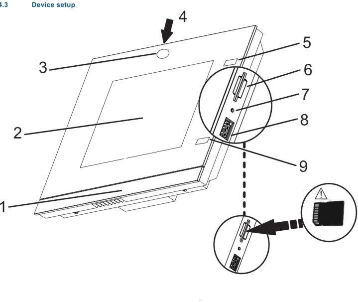
Pos: 14.6.1 /Layout bis 2014-11-11/Online-Dokumentation (+KNX)/Überschriften (--> Für alle Dokumente <--)/2. Ebene/A - F/Aufbau Gerät @ 33\mod_1361366224154_15.docx @ 278226 @ 2 @ 1 4.3 Device setup Pos: 14.6.2 /Layout bis 2014-11-11/Online-Dokumentation (+KNX)/Produktübersicht/KNX/KNX-Aktorik/ComfortPanel 3.0/KNX Technisches Handbuch/Aufbau GerätAufbau Gerät - KNX ... @ 40\mod_1418307260736_15.docx @ 308472 @ @ 1
1
2
3
5
6
7
4
8
!
9
Fig. 1: Overview of devices
1 Design bar | 2 Colour touchdisplay | 3 Camera | 4 Camera adjustment | 5+9 IR sensors 6 Slot for SD card | 7 Reset button | 8 Slot for USB stick
Note
The operating system of the Busch-ComfortTouch® is included on the USB stick supplied, which must be inserted into the matching slot on the Busch-ComfortTouch® prior to initial commissioning.
Any possible future operating system updates can then be performed simply via LAN / WAN, USB stick or SD card.
Caution
Risk of damaging the device due to touching! The USB connection contains many sensitive contacts. - They must not be touched directly!
Note
Pos: 14.8.1 /Layout bis 2014-11-11/Online-Dokumentation (+KNX)/Überschriften (--> Für alle Dokumente <--)/2. Ebene/G - L/Lieferumfang @ 33\mod_1361366589132_15.docx @ 278274 @ 2 @ 1 4.4 Scope of supply Pos: 14.8.2 /Layout bis 2014-11-11/Online-Dokumentation (+KNX)/Produktübersicht/KNX/KNX-Aktorik/ComfortPanel 3.0/KNX Technisches Handbuch/Lieferumfang/Lieferumfang @ 33\mod_1361365428309_15.docx @ 278033 @ @ 1
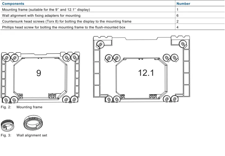
Components Number
Mounting frame (suitable for the 9’’ and 12.1’’ display) 1 Wall alignment with fixing adapters for mounting 6 Countersunk head screws (Torx 8) for bolting the display to the mounting frame 2 Phillips head screw for bolting the mounting frame to the flush-mounted box 4
Fig. 2: Mounting frame
Fig. 3: Wall alignment set
Pos: 14.9 /Layout bis 2014-11-11/Online-Dokumentation (+KNX)/Steuermodule - Online-Dokumentation (--> Für alle Dokumente <--)/++++++++++++ Seitenumbruch ++++++++++++ @ 9\mod_1268898668093_0.docx @ 52149 @ @ 1
Pos: 14.10.1 /Layout bis 2014-11-11/Online-Dokumentation (+KNX)/Überschriften (--> Für alle Dokumente <--)/2. Ebene/U - Z/Weitere benötigte Komponenten @ 33\mod_1361366730557_15.docx @ 278306 @ 2 @ 1
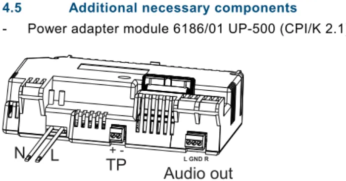
4.5 Additional necessary components Pos: 14.10.2 /Layout bis 2014-11-11/Online-Dokumentation (+KNX)/Produktübersicht/KNX/ComfortPanel 3.0/KNX Technisches Handbuch/Weitere benötigte Komponenten/Weitere benötigte Komponenten - ABB @ 35\mod_1363336229774_15.docx @ 287790 @ @ 1
- Power adapter module 6186/01 UP-500 (CPI/K 2.1) [ABB i-bus® KNX]
Fig. 4: Power adapter module 6186/01 UP-500 (CPI/K 2.1)
Note
All necessary clamps are enclosed!
Power adapter module 6186/01 UP-500 (CPI/K 2.1) must be used for ABB i-bus® KNX. It contains
twisted pair clamps.
- Flush-mounted installation box 8136/01 UP-500 (MD/U 6.1) (alternatively, also flush-mounted installation boxes 8136/UP-500 (MD/U 5.1) or 6136/UP (MD/U 1.1) can be used)
Pos: 14.11 /Layout bis 2014-11-11/Online-Dokumentation (+KNX)/Steuermodule - Online-Dokumentation (--> Für alle Dokumente <--)/++++++++++++ Seitenumbruch ++++++++++++ @ 9\mod_1268898668093_0.docx @ 52149 @ @ 1 Pos: 14.12.1 /Layout bis 2014-11-11/Online-Dokumentation (+KNX)/Überschriften (--> Für alle Dokumente <--)/2. Ebene/A - F/Farbkonzept @ 33\mod_1361366298104_15.docx @ 278242 @ 2 @ 1
4.6 Colour concept Pos: 14.12.2 /Layout bis 2014-11-11/Online-Dokumentation (+KNX)/Produktübersicht/KNX/KNX-Aktorik/ComfortPanel 3.0/KNX Technisches Handbuch/Farbkonzept/Farbkonzept @ 33\mod_1361365475354_15.docx @ 278065 @ @ 1
The Busch-ComfortTouch® is equipped with an intelligent, intuitive operating concept. The basis is a consistent
colour orientation for a better overview and faster recognition of the control element functions. The functions "Light", "Blinds", "Heating" and "Scenes" are illuminated in colour code (colour code on the operating surfaces) as follows:
B
Fig. 5: Colour concept
Colour Function assignment
Yellow (like the sun) Light control Blue (like the sky) Blind functions Orange (like warmth) Climate functions Magenta (stands for extravagance) Scenes
Pos: 15 /Layout bis 2014-11-11/Modul-Struktur/Online-Dokumentation/Steuermodule - Online-Dokumentation (--> Für alle Dokumente <--)/++++++++++++ Seitenumbruch ++++++++++++ @ 9\mod_1268898668093_0.docx @ 52149 @ @ 1
N
L
TP
Audio out
L GND R-Pos: 17.1 /Layout bis 2014-11-11/Online-Dokumentation (+KNX)/Überschriften (--> Für alle Dokumente <--)/1. Ebene/S - T/Technische Daten @ 11\mod_1279185386320_15.docx @ 83019 @ 2 @ 1
5
Technical data
Pos: 17.2.1 /Layout bis 2014-11-11/Online-Dokumentation (+KNX)/Überschriften (--> Für alle Dokumente <--)/2. Ebene/U - Z/Übersichtstabelle @ 33\mod_1361369213708_15.docx @ 278559 @ 1 @ 1 5.1 Overview table Pos: 17.2.2 /Layout bis 2014-11-11/Online-Dokumentation (+KNX)/Technische Daten/KNX/KNX-Aktorik/ComfortPanel 3.0/KNX Technisches Handbuch/Übersichtstabelle/Übersichtstabelle @ 33\mod_1361367419554_15.docx @ 278342 @ @ 1
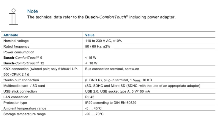
Note
The technical data refer to the Busch-ComfortTouch® including power adapter.
Attribute Value
Nominal voltage 110 to 230 V AC, ±10% Rated frequency 50 / 60 Hz, ±2% Power consumption
Busch-ComfortTouch®9 < 15 W
Busch-ComfortTouch®12 < 18 W
KNX connection (twisted pair; only 6186/01 UP-500 (CPI/K 2.1))
Bus connection terminal, screw-on "Audio out" connection (L GND R), plug-in terminal, 1 VRMS, 10 KΩ
Multimedia card / SD card (SD, SDHC and Micro SD (SDHC, with the use of an appropriate adapter) USB stick connection USB 2.0, USB socket type A, 5 V/100 mA
LAN connection RJ 45
Protection type IP20 according to DIN EN 60529 Ambient temperature range -5 … 45°C
Storage temperature range -20 … 70°C
Pos: 17.3 /Layout bis 2014-11-11/Online-Dokumentation (+KNX)/Steuermodule - Online-Dokumentation (--> Für alle Dokumente <--)/++++++++++++ Seitenumbruch ++++++++++++ @ 9\mod_1268898668093_0.docx @ 52149 @ @ 1 Pos: 17.4.1 /Layout bis 2014-11-11/Online-Dokumentation (+KNX)/Überschriften (--> Für alle Dokumente <--)/2. Ebene/G - L/Geräteanschluss / Anschlussbild @ 33\mod_1361369125277_15.docx @ 278543 @ 1 @ 1
5.2 Device connection / circuit diagram Pos: 17.4.2 /Layout bis 2014-11-11/Online-Dokumentation (+KNX)/Technische Daten/KNX/ComfortPanel 3.0/KNX Technisches Handbuch/Geräteanschluss / Anschlussbild/Geräteanschluss /Geräteanschluss / Anschlussbild - ABB @ 35\mod_1363336454376_15.docx @ 287822 @ @ 1
The connections of the Busch-ComfortTouch® are located on the power adapter module and on the rear of the display (LAN connection).
Fig. 6: Connections on the power adapter module (N, L; TP; Audio out) and on the display (LAN)
Note
All necessary clamps are enclosed!
Power adapter module 6186/01 UP-500 (CPI/K 2.1) must be used for ABB i-bus® KNX.
*) It contains twisted pair clamps.
Pos: 17.5 /Layout bis 2014-11-11/Online-Dokumentation (+KNX)/Steuermodule - Online-Dokumentation (--> Für alle Dokumente <--)/++++++++++++ Seitenumbruch ++++++++++++ @ 9\mod_1268898668093_0.docx @ 52149 @ @ 1
N L TP Audio out
+ -
L GND R L N*)
Pos: 17.6.1 /Layout bis 2014-11-11/Online-Dokumentation (+KNX)/Überschriften (--> Für alle Dokumente <--)/2. Ebene/A - F/Abmessungen /Abmessungen / Maßbild @ 33\mod_1361368902556_15.docx @ 278527 @ 1 @ 1
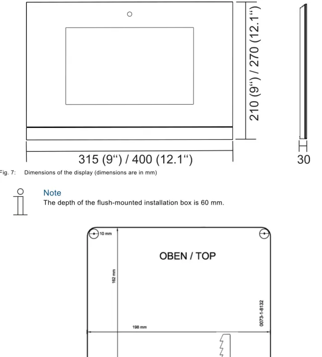
5.3 Dimensions / dimensional drawing Pos: 17.6.2 /Layout bis 2014-11-11/Online-Dokumentation (+KNX)/Technische Daten/KNX/KNX-Aktorik/ComfortPanel 3.0/KNX Technisches Handbuch/Abmessungen / Maßbild/Abmessungen /Abmessungen / Maßbild @ 33\mod_1361367502209_15.docx @ 278438 @ @ 1
The dimensions of the Busch-ComfortTouch® are available in the following illustrations.
It is installed exclusively with a special flush-mounted installation box. (Flush-mounted box 8136/01 UP-500 (MD/U 6.1)).
Fig. 7: Dimensions of the display (dimensions are in mm)
Note
The depth of the flush-mounted installation box is 60 mm.
Fig. 8: Dimensions of the drilling template for the flush-mounted installation box 8136/01 UP-500 (MD/U 6.1) (The Figure is not shown to scale)
Note
Alternatively, also flush-mounted installation boxes 8136/UP-500 (MD/U 5.1) or 6136/UP (MD/U 1.1) can be used).
Dimensions of the alternative flush-mounted installation boxes
Flush-mounted installation box Dimensions (H x W x D)
8136/UP-500 (MD/U 5.1) 169 mm x 257 mm x 60 mm 6136/UP (MD/U 1.1) 163.5 mm x 199 mm x 60 mm
Pos: 18 /Layout bis 2014-11-11/Modul-Struktur/Online-Dokumentation/Steuermodule - Online-Dokumentation (--> Für alle Dokumente <--)/++++++++++++ Seitenumbruch ++++++++++++ @ 9\mod_1268898668093_0.docx @ 52149 @ @ 1
Pos: 20.1 /Layout bis 2014-11-11/Online-Dokumentation (+KNX)/Überschriften (--> Für alle Dokumente <--)/1. Ebene/G - L/Installation @ 17\mod_1297676495008_15.docx @ 100410 @ 2 @ 1
6
Installation
Pos: 20.2.1 /Layout bis 2014-11-11/Online-Dokumentation (+KNX)/Sicherheitshinweise und Hinweise (--> Für alle Dokumente <--)/Warnhinweise/Sicherheit - 230 V + SELV @ 35\mod_1362749941351_15.docx @ 285394 @ @ 1
Warning
Electric voltage!Risk of death due to electrical voltage up to 230 V.
- Observe the spatial division of SELV electric circuits and other electric circuits. Otherwise short-circuits can occur!
- The insolating tube enclosed with the power adaptor can be used if necessary!
- Observe the relevant standards!
Pos: 20.2.2 /Layout bis 2014-11-11/Online-Dokumentation (+KNX)/Sicherheitshinweise und Hinweise (--> Für alle Dokumente <--)/Warnhinweise/Sicherheit - Fachkenntnisse @ 23\mod_1336559183027_15.docx @ 209179 @ 1 @ 1
6.1 Requirements for the electrician
Warning
Electric voltage!
Install the device only if you have the necessary electrical engineering knowledge and experience. • Incorrect installation endangers your life and that of the user of the electrical system.
• Incorrect installation can cause serious damage to property, e.g. due to fire.
The minimum necessary expert knowledge and requirements for the installation are as follows: • Apply the "five safety rules" (DIN VDE 0105, EN 50110):
1. Disconnect from power;
2. Secure against being re-connected; 3. Ensure there is no voltage;
4. Connect to earth and short-circuit; 5. Cover or barricade adjacent live parts. • Use suitable personal protective clothing. • Use only suitable tools and measuring devices.
• Check the supply network type (TN system, IT system, TT system) to secure the following power supply conditions (classic connection to ground, protective earthing, necessary additional measures, etc.).
Pos: 20.3 /Layout bis 2014-11-11/Online-Dokumentation (+KNX)/Steuermodule - Online-Dokumentation (--> Für alle Dokumente <--)/++++++++++++ Seitenumbruch ++++++++++++ @ 9\mod_1268898668093_0.docx @ 52149 @ @ 1
Pos: 20.4.1 /Layout bis 2014-11-11/Online-Dokumentation (+KNX)/Überschriften (--> Für alle Dokumente <--)/2. Ebene/A - F/Einbau /Einbau / Montage @ 33\mod_1361372259167_15.docx @ 278673 @ 2 @ 1
6.2 Installation / mounting Pos: 20.4.2 /Layout bis 2014-11-11/Online-Dokumentation (+KNX)/Installation/KNX/KNX-Aktorik/ComfortPanel 3.0/KNX Technisches Handbuch/Einbau / Montage/Einbau /Einbau / Montage @ 33\mod_1361372057729_15.docx @ 278640 @ 2333 @ 1
6.2.1 Preparation for installation
The Busch-ComfortTouch® is installed in mounted installation box 8136/01 UP-500 (MD/U 6.1). For flush-mounted or hollow-wall installation. This applies to the 9" and the 12.1" display.
Note
The flush-mounted installation boxes are not included in the scope of supply of the Busch -ComfortTouch®!
Generally the supplied mounting frame (for the 9" or 12.1" display) must be aligned with the wall alignment parts to produce an even surface. The wall alignment parts must be attached from behind on all screw holes according to the following figure (9" = 4, 12.1 = 6). Here it must be observed that the black fixing adapters are coded and can only be attached accordingly. The knurls on the the grey wall alignment parts must sit against the mounting frame.
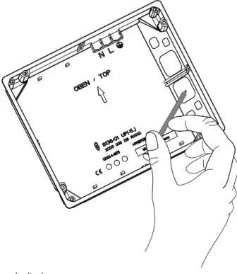
6.2.2 Installation of the flush-mounted wall box
1. Pierce the respective cable feed-through diaphragms with a pointed tool.
Fig. 10: Piercing the cable feed-through diaphragm
2. Insert the flush-mounted installation box in either a solid wall or hollow wall. Observe the following instructions / procedures.
Note
Ensure that each of the connecting cables for the power supply, KNX (option), LAN (option) and audio (option) must be guided through the cable feed-through.
6.2.3 Installing the wall alignment parts
Fig. 11: Installing the wall alignment parts
Note
The wall alignment is necessary so that the mounting frame sits on an even surface. Otherwise the display could be subject to stress.
The wall alignment parts can be screwed on at the correct height beforehand. However, they can also be aligned through the openings in the frame with a screwdriver after the mounting frame is installed.
Fig. 12: Adjusting the wall alignment parts
6.2.4 Attaching the mounting frame
1. Attach the mounting frame to the installed flush-mounted installation box.
The snap-in holder on the mounting frame must be located at the bottom edge of the frame!
Fig. 13: Attaching the mounting frame to the flush-mounted installation box
Note
The figure shows as example the attachment of the mounting frame for the 9" display.
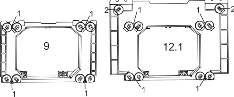
2. Fixing the mounting frame to the flush-mounted installation box with the enclosed countersunk head screws. Especially in public areas must the top frame section of the 12.1" display also be screwed to the wall.
Fig. 14: Fixture of the mounting frame for the 9" and 12.1" display
1 Screwed to the flush-mounted installation box (8136/01 UP-500 (MD/U 6.1) or 6136/UP (MD/U 1.1)) | 2 screwed to the wall
Note
Countersunk head screws must be used for screwing to the wall. The dowels must be selected to suit the type of wall.
Pos: 20.5 /Layout bis 2014-11-11/Online-Dokumentation (+KNX)/Steuermodule - Online-Dokumentation (--> Für alle Dokumente <--)/++++++++++++ Seitenumbruch ++++++++++++ @ 9\mod_1268898668093_0.docx @ 52149 @ @ 1
9
12.1
1
1
1
1
1
1
1
1
2
2
Pos: 20.6.1 /Layout bis 2014-11-11/Online-Dokumentation (+KNX)/Überschriften (--> Für alle Dokumente <--)/2. Ebene/A - F/Elektrischer Anschluss @ 21\mod_1328177051724_15.docx @ 138042 @ 3 @ 1
6.3 Electrical connection Pos: 20.6.2 /Layout bis 2014-11-11/Online-Dokumentation (+KNX)/Installation/KNX/ComfortPanel 3.0/KNX Technisches Handbuch/Elektrischer Anschluss/Einlegen des Netzteil-Moduls - ABB @ 36\mod_1363765620823_15.docx @ 289014 @ 2 @ 1
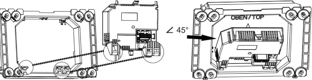
6.3.1 Inserting the power adapter module
The following example describes the installation and connection of a 9" display. The description also applies to the 12.1" display.
Note
Power adapter module 6186/01 UP-500 (CPI/K 2.1) is not included in the scope of supply of the
Busch-ComfortTouch®!
1. Press the latch-in lug of the power adapter module into the holders. For this the power adapter module must be attached at a 45° angle.
Fig. 15: Inserting the power adapter module
2. Install the connecting cable behind the power adapter module.
Pos: 20.6.3 /Layout bis 2014-11-11/Online-Dokumentation (+KNX)/Installation/KNX/ComfortPanel 3.0/KNX Technisches Handbuch/Elektrischer Anschluss/Aufklappen des Netzteil-Moduls @ 35\mod_1363337473211_15.docx @ 287931 @ 2 @ 1
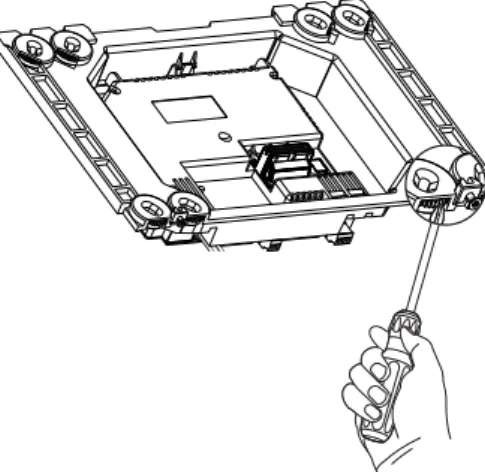
6.3.2 Opening out the power adapter module
After being inserted the power adapter module can be folded out and folded in.
Fig. 16: Folding the power adapter module in and out
Note
The power adapter module can only be pulled out in a 45° position.
Pos: 20.6.4 /Layout bis 2014-11-11/Online-Dokumentation (+KNX)/Steuermodule - Online-Dokumentation (--> Für alle Dokumente <--)/++++++++++++ Seitenumbruch ++++++++++++ @ 9\mod_1268898668093_0.docx @ 52149 @ @ 1
Pos: 20.6.5 /Layout bis 2014-11-11/Online-Dokumentation (+KNX)/Installation/KNX/ComfortPanel 3.0/KNX Technisches Handbuch/Elektrischer Anschluss/Anschließen des Netzteil-Moduls - ABB @ 35\mod_1363337596899_15.docx @ 287946 @ 2 @ 1
6.3.3 Connecting the power adapter module 1. Fold the power adapter module toward the front.
2. Use the WAGO terminals enclosed with the power adapter module to connect the power supply cables (L and N from the power adapter and from the supply line).
3. Plug the WAGO terminals into the top right-hand corner of the flush-mounted installation box. 4. Connect the KNX cable (optional) and the audio cable (optional) to the respective screw terminals.
Fig. 17: Electrical connection of the power adapter module
Note
Power adapter module 6186/01 UP-500 (CPI/K 2.1) must be used for ABB i-bus® KNX.
*) It contains twisted pair clamps.
5. Install all cables, except the LAN cable, behind the power adapter module. 6. Fold in the power adapter module so that it audibly locks onto the upper catch.
N
L
TP
Audio out
+ -
L GND RL N
7. Ensure that the optional LAN cable is installed in the cable compartment (1) next to the power adapter module.
It must not be bent.
Fig. 18: Cable compartment next to the power adapter module.
1 Cable compartment
Pos: 20.6.6 /Layout bis 2014-11-11/Online-Dokumentation (+KNX)/Installation/KNX/ComfortPanel 3.0/KNX Technisches Handbuch/Elektrischer Anschluss/Anschließen des LAN-Kabels @ 35\mod_1363337113879_15.docx @ 287886 @ 2 @ 1
6.3.4 Connecting the LAN cable
1. For LAN operation insert the RJ45 plug of the LAN cable into the RJ45 socket on the rear of the display.
Fig. 19: RJ45 socket for LAN operation
Pos: 20.6.7 /Layout bis 2014-11-11/Online-Dokumentation (+KNX)/Steuermodule - Online-Dokumentation (--> Für alle Dokumente <--)/++++++++++++ Seitenumbruch ++++++++++++ @ 9\mod_1268898668093_0.docx @ 52149 @ @ 1
Pos: 20.6.8 /Layout bis 2014-11-11/Online-Dokumentation (+KNX)/Installation/KNX/ComfortPanel 3.0/KNX Technisches Handbuch/Elektrischer Anschluss/Aufsetzen des Displays @ 35\mod_1363337200550_15.docx @ 287901 @ 2 @ 1
6.3.5 Mounting the display
1. Place the top inner edge (camera module top) onto the clamping teeth of the mounting frame.
Fig. 20: Mounting the display onto the mounting frame
2. Pressing the display onto the mounting frame
3. Screw the display to the mounting frame (1). Use the enclosed size 8 TORX screws. A standard TORX bit can be used for the screw attachment.
Fig. 21: Screwing the display to the mounting frame
4. Adjust the viewing angle of the internal camera with the adjusting screw (Phillips head screw). The adjusting screw is located above the display on the mounting frame.
Fig. 22: Adjusting screw for the internal camera
5. After commissioning and project planning, carry out the fine adjustment with the aid of an application (via "System setting") in the Busch-ComfortTouch®.
6. Remove the protective foil.
Pos: 20.6.9 /Layout bis 2014-11-11/Online-Dokumentation (+KNX)/Installation/KNX/ComfortPanel 3.0/KNX Technisches Handbuch/Elektrischer Anschluss/Demontage @ 35\mod_1363337257641_15.docx @ 287916 @ 1 @ 1
6.3.6 Dismantling
They are dismantled in the reverse order.
Pos: 21 /Layout bis 2014-11-11/Online-Dokumentation (+KNX)/Steuermodule - Online-Dokumentation (--> Für alle Dokumente <--)/++++++++++++ Seitenumbruch ++++++++++++ @ 9\mod_1268898668093_0.docx @ 52149 @ @ 1
Pos: 22.1 /Layout bis 2014-11-11/Online-Dokumentation (+KNX)/Überschriften (--> Für alle Dokumente <--)/1. Ebene/A - F/Erstinbetriebnahme @ 17\mod_1299234649340_15.docx @ 100978 @ 1 @ 1
7
Start-up
Pos: 22.2 /Layout bis 2014-11-11/Online-Dokumentation (+KNX)/Erstinbetriebnahme/KNX/KNX-Aktorik/ComfortPanel 3.0/KNX Technisches Handbuch/Erstinbetriebnahme @ 33\mod_1361430424661_15.docx @ 278774 @ @ 1
After the successful installation, initial commissioning can start. For this the current Firmware that is available on the USB stick must be installed.
The device starts automatically when the power supply is connected. The application is prepared.
1. Please follow the instructions on the monitor.
Note
Initial commissioning with this application takes approximately 5 minutes.
The application starts automatically.
After the successful installation the following message appears.
3. Remove the USB stick.
Note
If the installation was unsuccessful, the following message appears.
4. Repeat the process by pressing the "Reset" button.
5. Now program the panel accordingly. To do this, follow the instructions in the following chapters.
Pos: 23 /Layout bis 2014-11-11/Modul-Struktur/Online-Dokumentation/Steuermodule - Online-Dokumentation (--> Für alle Dokumente <--)/++++++++++++ Seitenumbruch ++++++++++++ @ 9\mod_1268898668093_0.docx @ 52149 @ @ 1
Pos: 24.1 /Layout bis 2014-11-11/Online-Dokumentation (+KNX)/Überschriften (--> Für alle Dokumente <--)/1. Ebene/U - ZVorbereitung der Projektierung @ 24\mod_1338554119019_15.docx @ 215329 @ 1 @ 1
8
Preparation for project planning
Pos: 24.2 /Layout bis 2014-11-11/Online-Dokumentation (+KNX)/Vorbereitung der Projektierung/KNX/KNX-Aktorik/ComfortPanel 3.0/KNX Technisches Handbuch/Einführung @ 33\mod_1361431077198_15.docx @ 278905 @ @ 1
The individual adaptation of the Busch-ComfortTouch®is carried out with the aid of project planning software
"IP-Project 3“. This software is an application especially created for project planning of the Busch-ComfortTouch®. This software must first be installed on a computer (PC). All project planning that has been created can then be simply transferred to each of the Busch-ComfortTouch®units that are connected or linked to the network.
Pos: 24.3.1 /Layout bis 2014-11-11/Online-Dokumentation (+KNX)/Überschriften (--> Für alle Dokumente <--)/2. Ebene/A - F/Anforderungen an die Rechnerausstattung @ 33\mod_1361431008937_15.docx @ 278890 @ 2 @ 1
8.1 Requirements for computer equipment Pos: 24.3.2 /Layout bis 2014-11-11/Online-Dokumentation (+KNX)/Vorbereitung der Projektierung/KNX/KNX-Aktorik/ComfortPanel 3.0/KNX Technisches Handbuch/Anforderungen an die Rechnerausstattung/Anforderungen an die Rechnerausstattung @ 33\mod_1361430777852_15.docx @ 278793 @ 33 @ 1
For the faultless operation of IP-Project 3 it is recommended to use the following basic hardware and software equipment:
8.1.1 Hardware
Hardware Operating system Minimum requirement
Processor Windows 7 (32 / 64 Bit) 2.0 / 1.6 GHz Dual Core Working storage Windows 7 (32 / 64 Bit) 2 GB RAM
Graphics card - 128 MB graphics memory
Hard disc - 40 GB with 15 GB free storage space Audio output - Available
Internet access - Available
8.1.2 Software
Software Operating system Minimum requirement
Graphics card - DirectX 9.0 with WDDM driver Pixel Shader 2.0
32 Bit per pixel
Pos: 24.4 /Layout bis 2014-11-11/Online-Dokumentation (+KNX)/Steuermodule - Online-Dokumentation (--> Für alle Dokumente <--)/++++++++++++ Seitenumbruch ++++++++++++ @ 9\mod_1268898668093_0.docx @ 52149 @ @ 1
Pos: 24.5.1 /Layout bis 2014-11-11/Online-Dokumentation (+KNX)/Überschriften (--> Für alle Dokumente <--)/2. Ebene/G - L/Installation von IP-Project 3 @ 33\mod_1361431244448_15.docx @ 278922 @ 2 @ 1
8.2 Installation of IP-Project 3 Pos: 24.5.2 /Layout bis 2014-11-11/Online-Dokumentation (+KNX)/Vorbereitung der Projektierung/KNX/KNX-Aktorik/ComfortPanel 3.0/KNX Technisches Handbuch/Installation von IP-Project 3Installation von IP-Project 3 @ 40\mod_1418379354913_15.docx @ 308669 @ @ 1
In the following the installation of commissioning software IP-Project 3 (IPP) for the Busch-ComfortTouch® is described.
Note
Please observe the hardware and software requirements listed above for a proper installation and function of the commissioning software.
In particular, you need to have full administrator rights to the operating system. 1. Start the install wizard by double clicking the file "setup_IPP3_ABB_vX.Y.exe".
The file is available in the electronic catalogue at www.busch-jaeger-catalogue.com.
2. In the window that opens select the installation language from the 6 languages (DE, EN, FR, ES, IT and NL).
3. Confirm the selection with "OK".
4. In the window that opens read the licensing agreement for the use of commissioning software IP-Project 3.
5. Click on the "Accept" button if you agree with the terms and conditions and proceed with the installation. 6. If you click on the "Cancel" button, the installation is ended and the commissioning software is not installed.
7. If necessary, in the following dialog window select the individual components of the commissioning software. The IP-Project 3 files are absolutely necessary for the commissioning software to function and can therefore not be de-selected.
8. After clicking button "Continue", create a target directory for the installation program. By default, this is: "C:\Program Files\IPP3\".
9. Confirm this dialog window by clicking the "Install" button.
he installation wizard carries out the installation to the target directory.
10. Observe the progress bar for visually monitoring the progress of the installation.
11. When the installation is completed, the installation procedure can be ended by clicking the "Quit" button.
Note
Please check for possible software updates (service releases) on the Internet at www.busch-jaeger-katalog.de, to be up-to-date with the most current software.
However, in IP-Project 3 you can set that available updates are automatically installed each time the program is started.
Pos: 24.6 /Layout bis 2014-11-11/Online-Dokumentation (+KNX)/Steuermodule - Online-Dokumentation (--> Für alle Dokumente <--)/++++++++++++ Seitenumbruch ++++++++++++ @ 9\mod_1268898668093_0.docx @ 52149 @ @ 1
Pos: 24.7.1 /Layout bis 2014-11-11/Online-Dokumentation (+KNX)/Überschriften (--> Für alle Dokumente <--)/2. Ebene/A - F/Einbindung in das KNX-System @ 33\mod_1361431298679_15.docx @ 278938 @ 2 @ 1
8.3 Integration into the KNX system Pos: 24.7.2 /Layout bis 2014-11-11/Online-Dokumentation (+KNX)/Vorbereitung der Projektierung/KNX/KNX-Aktorik/ComfortPanel 3.0/KNX Technisches Handbuch/Einbindung in das KNX-SystemEinbindung in das KNX-System @ 40\mod_1418380509461_15.docx @ 308685 @ 3333 @ 1
Note
The device meets KNX guidelines and can be used as a product of the KNX system. Detailed expert knowledge by means of KNX training sessions for a better understanding is assumed.
8.3.1 Installation of the Busch-ComfortTouch®ETSx Macro
For the correct importation and exportation of group addresses a special macro must be installed for the for the
Busch-ComfortTouch®. This macro can then be called up in the ETSx via additional buttons.
For this, a licensed version of the ETSx Professional software must be installed on the target computer for the installation. The minimum version is the ETS3.
Note
The macro for the ETS3 can be downloaded via the electronic catalogue ((www.busch-jaeger-catalogue.com)).
From the ETS4, a corresponding app must be downloaded via the electronic catalogue ((www.busch-jaeger-catalogue.com)).
Here the following installation procedure is almost identical.
8.3.2 Installation sequence
An installation wizard will assist you with the installation of the ETSx macros for the Busch-ComfortTouch®. 1. Start the install wizard by double clicking the file "Macros.exe".
2. In the window that opens select the installation language from the 6 languages (DE, EN, FR, ES, IT and NL). Then confirm with OK.
8.3.3 Integrating the Busch-ComfortTouch®into the ETSx
Start the ETSx and import the product data of the Busch-ComfortTouch®(.vd4 file) into the project data base via
the import function of the ETSx .
8.3.4 Further KNX settings in the Busch-ComfortTouch®.
For additional information about KNX settings in the Busch-ComfortTouch® use the online Help of IP-Project 3
(IPP).
Pos: 25 /Layout bis 2014-11-11/Modul-Struktur/Online-Dokumentation/Steuermodule - Online-Dokumentation (--> Für alle Dokumente <--)/++++++++++++ Seitenumbruch ++++++++++++ @ 9\mod_1268898668093_0.docx @ 52149 @ @ 1
Pos: 26.1 /Layout bis 2014-11-11/Online-Dokumentation (+KNX)/Überschriften (--> Für alle Dokumente <--)/1. Ebene/U - Z/Übersicht über IP-Project 3 (IPP) @ 33\mod_1361433797087_15.docx @ 278987 @ 1 @ 1
9
Overview of IP-Project 3 (IPP)
Pos: 26.2 /Layout bis 2014-11-11/Online-Dokumentation (+KNX)/Übersicht über IP-Project 3 (IPP)/KNX/KNX-Aktorik/ComfortPanel 3.0/KNX Technisches Handbuch/Einführung @ 33\mod_1361433735606_15.docx @ 278971 @ @ 1
The following chapters contain basic information about project planning software IP-Project 3 (IPP).
Note
A detailed description is available in the online Help of IP-Project 3.
IP-Project 3 is project planning software used to configure the Busch-ComfortTouch® for building automation from Busch-Jaeger / ABB. Each Busch-ComfortTouch® can be set up based on the wishes of your customers resulting
in completely individual solutions. IP-Project 3 guides you and offers you several version options making project planning simple, efficient and flexible.
Important tasks for project planning with IP-Project 3 are:
- Defining basic settings such as selecting the colour style or language for a Busch-ComfortTouch® (Basic settings).
- Creating a navigation by putting pages and page groups (containers) in the navigation bar (Create navigation structure).
- Configuring pages, e.g. selecting the page layout. - Configuring control elements, e.g. selecting button icons.
- Linking group addresses to establish the connection to actuators and sensors via the bus.
Pos: 26.3.1 /Layout bis 2014-11-11/Online-Dokumentation (+KNX)/Überschriften (--> Für alle Dokumente <--)/2. Ebene/S - T/Start von IP-Project 3 @ 33\mod_1361434572882_15.docx @ 279135 @ 2 @ 1
9.1 Start of IP-Project 3 Pos: 26.3.2 /Layout bis 2014-11-11/Online-Dokumentation (+KNX)/Übersicht über IP-Project 3 (IPP)/KNX/KNX-Aktorik/ComfortPanel 3.0/KNX Technisches Handbuch/Start von IP-Project 3/Start von IP-Project 3 @ 33\mod_1361434166794_15.docx @ 279007 @ @ 1
1. Start IPProject 3 by double clicking the program icon or via the start menu of the operating system (Start -> Programs --> IP-Project 3).
The blank main window of IP-Project 3 opens. The online Help will now guide you through the program. 2. If you are not an experienced user, we recommend that you go through the introductory exercise of the online
Help.
Pos: 26.4 /Layout bis 2014-11-11/Online-Dokumentation (+KNX)/Steuermodule - Online-Dokumentation (--> Für alle Dokumente <--)/++++++++++++ Seitenumbruch ++++++++++++ @ 9\mod_1268898668093_0.docx @ 52149 @ @ 1
Pos: 26.5.1 /Layout bis 2014-11-11/Online-Dokumentation (+KNX)/Überschriften (--> Für alle Dokumente <--)/2. Ebene/A - F/Bildschirmbereiche in IP-Project 3 @ 33\mod_1361434669489_15.docx @ 279151 @ 2 @ 1
9.2 Screen areas in IP-Project 3 Pos: 26.5.2 /Layout bis 2014-11-11/Online-Dokumentation (+KNX)/Übersicht über IP-Project 3 (IPP)/KNX/KNX-Aktorik/ComfortPanel 3.0/KNX Technisches Handbuch/Bildschirmbereiche in IP-Project 3/Bildschirmbereiche in IP-Project 3 @ 33\mod_1361434169637_15.docx @ 279023 @ @ 1
When using IP-Project 3 to plan, you work in several areas and on various levels. This section explains their purpose and how they are used.
1 2 3 4 5 6 7 8
Fig. 23: Overview of screen areas
1 Title bar | 2 Menu bar | 3 Icon bar | 4 Library area | 5 Working area | 6 Help area | 7 Parameter area | 8 Status bar
Screen area Function
Title bar [1] Shows the name of the project currently open.
Menu bar [2] Leads to the submenus of the menu bar entries "Project", "Edit", "Panel", "Tools", "View" and "Help". Icon bar [3] Allows quick access to various tools of the IP-Project 3 software via graphical icons.
Library area [4] Contains a tree structure representation of the entire project, administration functions (naming, creating, deleting), a library area for control elements and applications (availability in dependence on the level currently being edited in the working area) and an area for administering and creating external/internal group addresses.
Working area [5] Facilitates working on panel, navigation and page levels. Facilitates the allocation of free spaces via drag & drop. Makes a filing sector available in the upper area for "parking" temporary unused control elements and pages.
Help area [6] Makes a context-related excerpt from the online help available. Contains a to-do list (notes) with suggestions and its own to-do notes. Displays the result of a consistency check of the current view, of the complete panel and of the complete project.
Parameter area [7] Depending on the module (element) selected, it makes appropriate input and setting options available in the working area. Contains the access to expanded settings and editors of the applications.
Status bar [8] Shows panel and page in which project planning is currently being performed. Signals a general LAN connection status (online/offline). Contains a compact display of the results of the infrastructure detection ("x compatible panels found" / "No compatible panel found" / Compatible panel found").
The areas 4 (Library area) and 6 (Help area) can be faded in or out by clicking the narrow blue fields. The size can be changed by pulling on the grey boundary strip with the mouse button pressed.
The display in the IP-Project 3 software has been optimised for a screen resolution of 1280 x 1024 pixel. Also possible is 1024 x 768 pixel.
Pos: 26.6 /Layout bis 2014-11-11/Online-Dokumentation (+KNX)/Steuermodule - Online-Dokumentation (--> Für alle Dokumente <--)/++++++++++++ Seitenumbruch ++++++++++++ @ 9\mod_1268898668093_0.docx @ 52149 @ @ 1
Pos: 26.7.1 /Layout bis 2014-11-11/Online-Dokumentation (+KNX)/Überschriften (--> Für alle Dokumente <--)/2. Ebene/A - F/Erläuterung der Grundstruktur (Begriffe) @ 33\mod_1361434727681_15.docx @ 279167 @ 2 @ 1
9.3 Explanation of the basic structure (Terms) Pos: 26.7.2 /Layout bis 2014-11-11/Online-Dokumentation (+KNX)/Übersicht über IP-Project 3 (IPP)/KNX/KNX-Aktorik/ComfortPanel 3.0/KNX Technisches Handbuch/Erläuterung der Grundstruktur (Begriffe)/Erläuterung der Grundstruktur (Begriffe) @ 33\mod_1361434172411_15.docx @ 279039 @ 345554555445554555 @ 1
9.3.1 Areas
Observe also section "Screen areas in IP-Project 3".
9.3.1.1 Library area
The left side in IP-Project 3 is called the "Library area" because it includes all elements required for project planning (pages, control elements, etc.). The library area consists of sections "Overview“, "Elements“ and "Actions“.
Sub-section "Übersicht“
Sub-section "Overview" shows you all Busch-ComfortTouch® in your project based on the icon. If you see no
Busch-ComfortTouch®, you have to first add them. Under "Navigation structure“ you see the pages allocated to a
Busch-ComfortTouch®. If you see no pages, you have to first add them.
You can save pages and control elements as templates in IP-Project 3 so you can reuse them later. The templates are then found in section "Overview“ under "My Templates“.
Also the so-called "Cross References“ are located in the library area in section "Übersicht“.
Sub-section "Elements“
The sub-section "Elements“ lists the modules (elements) for compiling a Busch-ComfortTouch®. Depending on
whether you are creating the Busch-ComfortTouch® navigation or you want to add control elements to a page, section "Elements“ contains the respective elements.
You can save pages and control elements as templates in IP-Project 3 so you can reuse them later. The templates are then found in the bottom My Templates“ tab.
Also the so-called "Elements“are located in the library area in section "Cross References“.
Sub-section "Aktionen“
In sub-section "Actions“ you can administer group addresses and from there link them with the communication objects of a control element. If there are no group addresses, you must either import existing group addresses or create new ones yourself.
9.3.1.2 Working area
The middle section (between library area and Help area) in IP-Project 3 is called working area.
Clipboard
The top part of the working area is separated by a line. Above the line is the clipboard area in which you can temporarily store modules (elements) on the navigation and page level. Drag a module (element) from the bottom part of the working area to the clipboard.
Tab "Panel“
The "Panel“tab in the working area is the area in which configuration primarily takes place. There you combine elements (pages, containers, control elements, etc.) into a Busch-ComfortTouch®. All modules are outlined to
allow you to assess the appearance of the final Busch-ComfortTouch® already during the configuration. The configuration of a Busch-ComfortTouch® in IP-Project 3 stretches over three levels (see section "Levels").
The "Panel“tab in the working area adjusts to the respective level as follows: 1. Project level
Add the Busch-ComfortTouch® to the project in the top level and make basic settings. The "Panel“ tab in the working area shows a list of all Busch-ComfortTouch® panels added in the project.
2. Navigation level
Create the navigation structure in the middle level by adding pages. The working area shows the four sections of the navigation bar of the selected Busch-ComfortTouch® and another section which only includes the start
page. 3. Page level
Configure pages in the bottom level by adding Control elements or making application settings. The "Panel“ tab in the working area shows the selected start, operating or application page.
Tab "Objects“
The "Objects“ tab in the working area is virtually the "rear" of the Busch-ComfortTouch® and the control elements via which you can establish a connection to the actuators.
There each Busch-ComfortTouch® and each control element has a number of so-called communication objects
for linking with group addresses.
The configuration of a Busch-ComfortTouch® in IP-Project 3 stretches over three levels (see section "Levels").
The "Objects“ tab in the working area adjusts to the respective level as follows: 1. Project level
You link Busch-ComfortTouch® communication objects to group addresses in the top level. The "Objects“ tab in the working area shows the communication objects of all Busch-ComfortTouch® panels in the project.
2. Navigation level
In the middle level there is no "Objects“ tab in the working area. 3. Page level
In the bottom level you link the communication objects of an application page or the control elements to group addresses. The "Objects“ tab in the working area shows the communication objects of the application page or all control elements of a start or operating page.
9.3.1.3 Parameter area
The parameter area shows the parameters of the module you have selected in the working area (marked). If no module is selected, the parameters of the parent element are displayed:
Selected parameter Level Parameter of the parent element
Busch-ComfortTouch® selected Project level Designation of the Busch-ComfortTouch®, access to
"Grundeinstellungen“, "Anwendungseinstellungen“ and editors. No module selected Project level No parameters.
Start page selected Navigation level Name, view and room image.
Operating or application page selected. Navigation level Title (designation), icon and visible container. No module selected Navigation level See Busch-ComfortTouch® selected.
Operating or application page selected. Page level Title (designation) as well as access to ""Extended settings". Control element selected Page level Title (designation), type and icons (depending on control
element) as well as access to ""Extended settings" - statuses of the control element.
No module selected Page level See "Start page" selected
9.3.1.4 Help area
The right page in IP-Project 3 is called the "Help area". The help area provides support when carrying out configurations. It is divided into the sections "Advice“, "My Notes“ and "Consistency Check“.
Sub-section "Advice“
The "Advice“ section shows you a brief outline of help topics related directly to your current task in IP-Project 3. If you press a link there, this help system opens.
Sub-section "My Notes“
Sub-section "My notes" shows all comments about the opened project. These can be element-related comments that assist the project planner to record why certain settings were made for this element. The element in the working area is marked with a yellow square. Also comments about the entire project can be made. The notes can be used as one's own to-do list.
Sub-section "Consistency Check“
Sub-section Consistency Check“ is used to check for inconsistencies in your project. You can check the current view ("Check current view“), the current Busch-ComfortTouch® ("Check panel“) or the overall project ("Check