337
Overview
The optional air brakes system on the Blue Bird Vision utilizes Meritor cam-operated drum brakes, with captive spring brake chambers on the rear axle providing parking brake and safety backup functions. A gear driven Wabco air compressor mounted on the engine operates whenever the engine is running. A governor mounted directly to the rear of the compressor monitors system air pressure and switches the com-pressor between load and unload modes to maintain a normal operating pressure range within the storage tanks.
As air is compressed, moisture vapor tends to condense inside the storage tanks. The tanks are equipped with bleeder valves to allow removal of this built-up mois-ture. Some buses are equipped with an air dryer to assist collection and expulsion of the excess moisture. Air from the compressor passes through the air dryer before passing into the storage tank. The storage tank is mounted under the bus, outboard the frame rail on the driver’s side, and on buses equipped with an air dryer, the dryer is mounted inboard of the frame rails just forward of the storage tank.
The system is divided into two separate circuits; one for rear brakes (primary) and one for front (secondary). The brake treadle valve mounted on the front side of the driver’s fire wall is connected to the brake pedal, and receives pressure from both the primary and secondary tanks. The treadle valve directly controls the pressure and volume of air delivered to the front brakes. However, for the rear brakes, the treadle valve provides a signal only, which actuates a relay valve mounted to the frame crossmember just forward of the rear axle. The relay valve receives the pressure and volume of air needed to operate the rear brakes directly from the primary tank, and controls that supply in response to the signals it receives from the treadle valve.
At each wheel, air pressure is delivered to a closed brake chamber, which en-cases a diaphragm. The increased pressure area behind the diaphragm results in an increased mechanical advantage to move a pushrod, which rotates the shaft of an S-cam situated between the ends of two brake shoes. As the S-cam rotates, it spreads the brake shoes, pushing their friction linings against the inner wall of the drum to slow or stop the wheel.
Over time, as the friction linings of the brake shoes wear, the push rods of the brake chambers must travel farther in order to actuate the brakes. To compensate for this normal wear of the brake shoes, the push rod of each brake chamber is con-nected to the S-cam by way of a slack adjuster; a ratcheting mechanism which incre-mentally and automatically takes up the linkage slack as the brake shoes wear.
An important concept in air brake systems is the matter of releasing air pres-sure in order to release the brake. Generally speaking, when brakes are applied, a valve is opened to allow air pressure to activate a brake chamber. However, simply closing the valve thereafter does not release the brakes, because the air pressure that activated them is still present in the chambers. A means must be provided to quickly release the captive pressure when the driver releases the brake pedal. On the secondary (front brake) circuit of the Blue Bird Vision, this is accomplished by a quick release valve, mounted on the rear-facing side of the engine crossmember. Air goes to the quick release valve, which serves to tee the air pressure toward the left and right front wheels. On the rear, the relay valve performs the quick release function.
339
340
Before reaching the brake chambers at the front wheels, each of the two output lines from the QR-1 connect to an ABS modulator valve mounted on the inboard side of the frame rails near the wheel. For the rear brakes, left and right modulator valves are also mounted directly to the two output ports of the relay valve. Thus, there are four ABS modulator units, one for each wheel. Lines from the modulators then pro-ceed to the chambers.
The modulator valves incorporate quick release valves of their own, which aid in exhausting pressure from the brake chambers. But their primary function is to independently modulate braking force to each wheel in order to minimize wheel lock during braking.
The modulators receive electric signals from the ABS Electronic Control Unit (ECU) mounted on the support bracket of the Driver’s transmission control housing. The ECU is a computer which monitors electric signals it receives from wheel speed sensors mounted at each wheel, and uses this information to determine when wheel lock up (and, therefore, loss of traction) is about to occur. When the ECU makes such a determination, it signals the ABS modulator(s) for the affected wheel(s) to adjust the air pressure being applied to the wheel(s), using high frequency pulses. This helps maintain maximum traction by preventing the wheels from locking.
Parking brake and emergency brake function is provided by the rear axle brake chambers (MGM Type 30). Unlike the front chambers (MGM Type 20L), each rear chamber incorporates two mechanisms by which to extend their pushrods; one powered by air pressure during normal driving as described above (service brakes) and the other powered by a heavy duty spring enclosed in the brake chamber (spring brakes). The spring brakes provide rear braking in the case of primary brake system failure, and also perform as normal parking brakes. Whenever system air pressure is within normal operating range and the parking brake control is pushed in, a spring release valve, mounted on the front side of the same cross member as the relay valve, allows air pressure it receives directly from the secondary tank to compress the rear brake chamber springs, preventing them from actuating the rear brakes (the springs are “caged”). Whenever primary operating pressure is absent, the SR7 valve dumps the pressure which cages the springs in proportion to the amount of pressure the driver applies to the brake pedal. Thus, in the case of primary failure, the spring brakes take over braking function for the rear wheels. This condition is referred to as “spring brake modulation.” A warning buzzer and light are activated in the driver’s area.
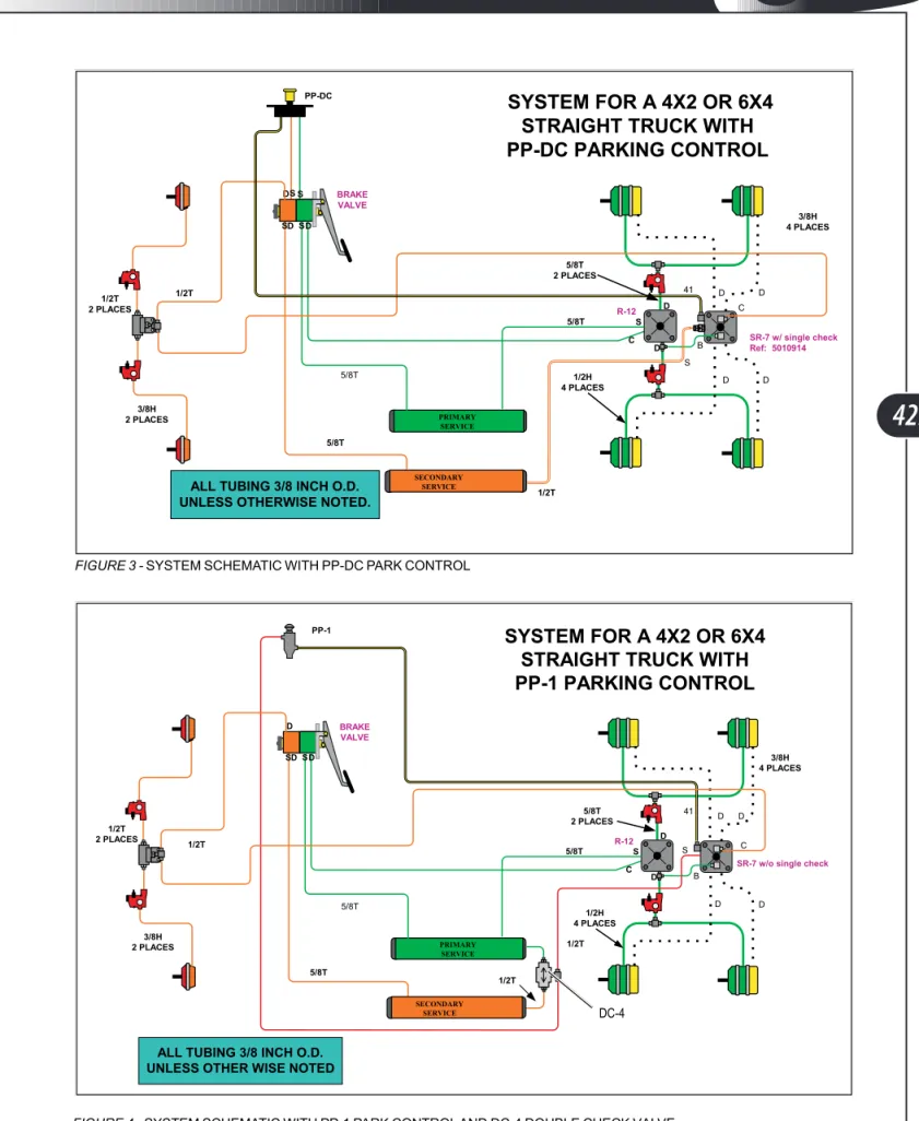
When the driver pulls the dash-mounted Parking Brake control valve (Bendix PP-DC), it signals the SR7 valve to fully dump the air caging the spring brakes, thereby causing them to serve as parking brakes. This signal pressure from the PP-DC must be present in order to cause the SR7 to cage (release) the spring brakes. This prevents the parking brakes from being released until system pressure is adequate for normal service brake operation.
341
Appendixes In This Chapter
Appendix 1. AD-9 Air Dryer. This Bendix Service Data Sheet describes in detail the function of the AD-9 Air Dryer, covers inspection and maintenance, and includes a troubleshooting chart.
Appendix 2. AD-IP Air Dryer. This Bendix Service Data Sheet describes in detail the function of the AD-IP (Integral Purge) Air Dryer, covers inspection and maintenance, and includes a troubleshooting chart.
Appendix 3. PP-DC Park Brake Valve. This Bendix Service Data Sheet describes in detail the function of the PP-DC , and includes inspection and testing procedures. Blue Bird does not recommend rebuilding of damaged air brake system valves. Appendix 4. SR-7 Spring Release Valve. This Bendix Service Data Sheet describes in detail the function of the SR-7, and includes inspection and testing procedures. Blue Bird does not recommend rebuilding of damaged air brake system valves.
Appendix 5. EC-30 ABS Controller Module. This Bendix Service Data Sheet describes in detail the EC-30, including blink code diagnostics and troubleshooting charts. Appendix 6. Meritor Slack Adjusters. Meritor Manintenance Manual 4B describes function, inspection, maintenance and adjustment of Meritor Automatic Slack Ad-justers.
Appendix 7. Haldex Slack Adjusters. This Haldex Service Manual describes function, inspection, and maintenance of Haldex Automatic Brake Adjusters.
Appendix 8. Meritor Cam Brakes. Meritor Manintenance Manual 4 describes func-tion, inspecfunc-tion, and maintenance of the cam brake assemblies.
On TechReference CD
The TechReference CD includes Bendix Service Data Sheets on the valves listed be-low. These documents provide detailed descriptions of the functioning of the valves, inspection proceedures, and troubleshooting. Note that Blue Bird does not recom-mend rebuilding of damaged air brake system valves.
• E-8P Dual Brake Valve. • R-12 Relay Valve. • QR-1 Quick Release Valve • M-32QR Antilock Modulator Valve • WS-20 Wheel Speed Sensor Also See…
The Hydraulc Brakes chapter of this manual includes a detailed procedure for remov-ing the rear disc rotor/hub assembly.
342
Brake Interlock
As a safety feature, Blue Bird Visions equipped with wheelchair lift doors incorporate an interlock system designed to automatically apply the service brakes when the lift door is open and the park brake valve is not set. The main components of the interlock system include a brake valve actuator (BVA), a pressure switch, an air-operated solenoid valve, and a pressure regulator valve. The BVA is mounted onto the brake treadle valve between it and the firewall. The other components are mounted on the driver side (bus interior) of the firewall to the left of the steering column just below the air accessory manifold.
The input port of the RV-3 pressure regulator valve is teed into the line from the delivery side of the PP-DC park brake valve. This is the line which delivers pressure to cage the spring brakes. When pressure
is present in this line, the RV-3 feeds a reduced pressure (approximately 70 psi) to the normally-closed solenoid valve.
The solenoid valve’s coil is wired to one of the MPX module’s Outputs through the V and U connectors of the 23 pin Deutsch main harness connector located at the upper right of the steering column. Thus, the interlock function is one of
the circuits controlled by the Vision’s Multiplex system.
Whenever conditions required for interlock exist (see MPX Ladder Logic line # 21), the MPX Module supplies a path to ground for the air solenoid valve, energizing it and causing it to open. The open solenoid valve allows pressure to pass to the pressure switch and the BVA. The BVA in turn applies it as braking pressure to the treadle valve exactly as if the driver had pressed the brake pedal.
The purpose of the pressure switch is to provide an active Interlock Feedback Input to the MPX module. (See Ladder Logic Line # 9.)
Brake Valve Actuator Brake Treadle Valve
Pressure Switch Solenoid Valve RV-3 Regulator Valve
343
PPDC Park Brake Valve
Solenoid Valve
RV3 Pressure Regulator
Brake Valve Actuator
Brake Valve DCM Main Connector 23 pin Deutsch Interlock Feedback Interlock Signal Delivery to Spring Brakes
Brake Interlock (units with air brakes)
Exhaust
344
Maintenance Overview
Wear and service life of brake system components varies according to the operat-ing conditions of the vehicle. Regular inspections and attentiveness to any unusual pedal feel (abruptness or sponginess), or sounds (for example, unusual air releases) is especially important. Air brake system maintenance includes items in all these categories:
• Daily tasks such as purging the air tanks to remove moisture and in cold cli-mates, inspecting the system purge valves for freezing.
• Regularly scheduled inspection of brake chamber push rod travel and auto-matic slack adjuster operation according to intervals in the Scheduled Main-tenance section.
• Routine maintenance of consumables such as replacement of Air Dryer desic-cant and/or filters. Service life will vary according to operating conditions. • Replacement or renewal of normal wear parts such as brake shoes and
ro-tors.
• Careful inspection of all air lines and fittings, checking for cracked, abraded, kinked, loose, or otherwise damaged lines.
• Inspection of components for proper operation. Blue Bird does not recom-mend disassembly or rebuilding of air brake valves and other components. When a component is found defective, replace it with a new or remanufac-tured unit.
[WARNING] Never attempt to disassemble a brake cylinder, even when it con-tains no compressed air. The spring brake cylinders enclose very powerful coil springs held under high mechanical compression. Any attempt to disassemble the brake chamber can result in injury or death.
When working on the air brake system, always follow these precautions in addition to those in the Warnings and Cautions section:
• Park the vehicle on a level surface, stop the engine, and chock the wheels securely. Remember, during servicing, the brakes will not be available to pre-vent the bus from rolling.
• If wheel end components are to be serviced which require wheel removal, support the bus by proper jack stands under the frame rails. Do not rely upon a jack to support the bus during servicing.
• Fully drain all air tanks .before removing any air lines, fittings, or components. Never remove an air line which is under pressure. Never remove a component or plug unless you are certain all system pressure has been depleted. • Disconnect the negative battery terminal. Some air brake system components
have electrical connections.
345
Air Compressor
The Blue Bird Vision’s air compressor is a gear driven single cylinder Wabco unit with turbocharged intake, and is mounted to the left side of the Caterpillar engine.
Being directly gear driven by the engine, the air compressor turns continually while the engine is running. But the actual compression of air is cycled on (load mode) or off (unload mode) by an unloading mechanism in the compressor. This maintains a normal operating range of pressure within the system. The pressures at which the compressor switches between load and unlode modes are set by the governor, mounted on the rear side of the compressor.
Servicing
As an integral part of the engine package, the compressor is installed by Caterpil-lar. For additional general information on the air compressor, refer to the Caterpillar engine manual supplied with your vehicle. For more detailed service and mainte-nance information, contact your local Caterpillar dealer and ask for Service Manual RENR2314.
Air Compressor Governor (D-2)
The Bendix D-2 air compressor governor operates in con-junction with the unloading mechanism of the compressor to automatically keep the air pressure in the system between 100 and 120 psi.
The governor’s porting includes a reservoir port, which connects to the wet tank; unloader ports which connect to the compressor’s unloader mechanism and to the air dryer’s control port; and an exhaust port which opens to the atmo-sphere.
Air pressure from the Blue Bird Vision’s wet tank enters
the D-2’s reservoir ports and acts upon a piston in opposition to a pressure setting spring. When the pressure from the tanks is sufficient to overcome the tension of the spring, an inlet/exhaust valve integrated in the piston closes the exhaust and opens the inlet passage. Air pressure can then pass around the inlet valve, through the piston and out the unloader port to activate the unloader mechanism of the compressor. This unload pressure also travels to the air dryer to open the purge valve, allowing the air dryer to expel accumulated moisture and contaminates.
When the system reservoir pressure drops to the level insufficient to overcome the pressure setting spring, the spring moves the piston to close the inlet valve and open the exhaust. This allows air in the unloader line to escape back through the piston and out the exhaust port. The compressor goes into load mode and begins compressing air to raise the system pressure in the wet tank.
On the Blue Bird Vision, the governor is set to maintain system pressure between 100 and 120 psi. When the system pressure drops to 100 psi, the governor de-acti-vates the compressor’s unloader mechanism. When system pressure rises to 120 psi, the governor activates the compressor’s unloader mechanism. Appendix 1 contains additional information on the inner workings of the D-2 governor.
Bendix D-2 Governor Bendix Publication SD-01-503
346
Servicing
Bendix recommends performing operating and leakage tests on the D-2 governor every 6 months, 50,000 miles, or 1800 hours; whichever comes first. Instructions for leak and operating tests are provided in Air Brakes Appendix 1.
Troubleshooting
Conditions that may indicate problems with the D-2 governor include:
• Over pressure of the system. The compressor fails to go into unload mode when system pressure reaches 120 psi.
• Under pressure of the system. The compressor fails to go into load mode when system pressure drops to 100 psi.
Adjustment
The activation pressure of the D-2 governor is adjustable by means of an adjustment screw under the plastic cap in the end of the governor body. Note that adjustment affects both the cut-in and cut-out pressures. The pressure difference or range be-tween cut-in and cut-out will remain constant and is not adjustable. Before deciding to adjust the governor pressure setting, be sure to check the system in and cut-out pressures with an accurate test gauge. To adjust the D-2 governor:
1. Unscrew the top cover from the governor, exposing the adjusting screw. The adjusting screw is slotted on its outer end.
2. Loosen the adjusting screw locknut.
3. To raise the pressure setting, turn the adjusting screw counter-clockwise. To lower the pressure setting, turn the adjusting screw clockwise. Be careful not to overadjust. Each quarter turn of the adjusting screw raises or lowers the pressure setting approximately 4 psi.
4. When proper adjustment is obtained, tighten the adjusting screw locknut and replace the cover.
Removal
The D-2 governor is fastened to the compressor body by two Allen-head bolts, one on each side of the rear side unloader port. To remove:
1. Block and securely hold vehicle by means other than air brakes.
2. Drain the air brake system by opening the purge valve at the bottom of the air tank.
347
4. Disconnect from the unloader port the line which leads to the air dryer. 5. Remove the two Allen head bolts and carefully remove the governor, taking
care not to damage the rubber gasket. Installation
Reverse the removal steps. If the gasket was damaged during removal, replace it with a new gasket. Torque the mounting bolts to 18–20 ft. lbs. (24.4–27.1 Nm).
Air Dryer (Optional)
Your Blue Bird Vision may be equipped with one of two Ben-dix air dryer models; the AD-IP integral purge dryer or the AD-9. The two dryers are similar in function. The main differ-ence is that the AD-IP contains a desiccant cartridge which can be changed without removing the dryer assembly.
The air dryer operates in two modes, depending on whether the compressor is in load mode (compressing air) or unload mode (not compressing).
When the compressor is in load mode, the air dryer oper-ates in its charge cycle. Air from the compressor enters the supply port of the air dryer. In the body of the air dryer, the air changes direction several times, reducing its temperature and causing contaminates to collect in the dryer’s internal sump. The air continues its flow into a cartridge contain-ing two filtercontain-ing stages. The first stage is an oil separator, which removes water in liquid form as well as oil and solid
contaminates. The second stage is a desiccant drying bed. Water vapor contained in the air flowing through the desiccant column is attracted to and condenses upon the surfaces of the desiccant particles.
Dry air exits the air dryer through a check valve and proceeds to the wet tank reservoir, ready for use by the system.
When system pressure reaches the cutout setting of the governor, the governor pressurizes its unloader ports, which signals the compressor to switch to unload mode (stop compressing) and signals the air dryer to switch to its purge cycle. Con-trol pressure from the governor enters the air dryer’s conCon-trol port, causing a purge valve to open the air dryer’s exhaust port and an initial audible burst of air is heard as moisture, oil, and contaminates are expelled. The purge valve remains open (after the audible burst) as long as the control pressure from the governor is present. A check valve in the delivery port prevents pressurized air from the storage tank from backing up into the dryer, but the air still inside the dryer reverses direction, flows back through the desiccant column, serving to remove most of the water adhering to the desiccant. Thus, the purge process effectively reactivates the desiccant. Gener-ally 15–30 seconds are required for the entire purge volume to pass back through the desiccant drying bed. The purge valve assembly of the air dryer incorporates an electric heating element and thermostat to prevent freezing in cold climates.
348
Servicing & Inspection
Over time, the desiccant cartridge becomes less effective and eventually must be re-placed. Bendix lists three years as typical cartridge life and recommends replacement at intervals of 10,800 hours, 300,000 miles, or 36 months. Actual service life is highly dependent upon operation conditions and climate. Blue Bird recommends inspect-ing the air dryer every 3 months or 24,000 miles, whichever occurs first.
• Whenever purging the air tanks (see Scheduled Maintenance section), watch for unusual amounts of moisture accumulation. In climates and seasons in which ambient temperatures vary more than 30 degrees in a day, small amounts of moisture due to condensation inside the tanks should not be considered an indication that the dryer is not performing properly. Similarly, trace amounts of oil in the system may be normal and should not, in itself, be considered a reason to replace the desiccant; oil stained desiccant can func-tion adequately.
• In cold months, visually inspect the air dryer’s exhaust port for signs of freez-ing, which may indicate improperly functioning heating of the purge valve. Air Brakes appendixes 2 and 3 (Bendix publications 08-2412 for AD-9; and SD-08-2424 for AD-IP) contain additional helpful information on testing, cleaning, and inspection.
Removal (AD-9)
The AD-9 dryer must be removed to replace its internal desiccant cartridge. 1. Park the bus on a level surface and apply the parking brake. Stop the engine.
Chock wheels to prevent movement. Disconnect the negative terminal of the battery.
2. Open the wet tank purge valve to drain the air brake system to 0 psi. 3. Disconnect the heater/thermostat electric connector from the air dryer’s
purge valve assembly.
4. Identify and disconnect the air lines connected to the air dryer at the delivery port (leads to wet tank), control port (leads to governor), and supply port (leads to compressor).
5. Loosen the 5/16 horizontal bolt and nut securing the upper mounting strap to the upper mounting bracket. It is not necessary to completely remove the nut and bolt. The nut is a special nut with an extended threaded shank which inserts into the mounting hole, allowing the clamp to be loosened sufficiently.
349
6. Remove the two 3/8” bolts mounting the air dryer body to the lower mount-ing bracket. Mark the locations of these two bolts on the body of the air dryer to aid in orienting the dryer correctly on re-installation.
7. Remove the air dryer by pulling the bottom flange clear of the lower mount-ing bracket tabs and slippmount-ing the dryer downward from inside the upper mounting clamp.
Installation
1. Slide the upper body of the dryer up into the upper mounting clamp. Posi-tion the bottom flange on top of the tabs of the lower mounting bracket. The dryer should rest on top of the bracket’s mounting tabs, not fasten below them.
2. Install the two lower mounting bolts, four special washers, and two lock nuts. Tighten to 270–385 in. lbs. (30.5–43.5 Nm).
3. Tighten the upper clamp’s bolt and nut to 80–120 in. lbs. (9–13.5 Nm). 4. Connect the air lines connected to the air dryer at the delivery port (leads to
wet tank), control port (leads to governor), and supply port (leads to com-pressor).
5. Connect the heater/thermostat electric connector to the air dryer’s purge valve assembly.
6. Before returning the Blue Bird Vision to service, perform the operation and leakage tests in Appendix 2.
Removal (AD-IP)
Note that it is not necessary to remove the AD-IP air dryer in order to change its desiccant cartridge.
1. Park the bus on a level surface and apply the parking brake. Stop the engine. Chock wheels to prevent movement. Disconnect the negative terminal of the battery.
2. Open all three tank bleed valves to drain the air brake system to 0 psi. 3. Disconnect the heater/thermostat electric connector from the air dryer’s
350
4. Identify and disconnect the air lines connected to the air dryer at the delivery port (leads to wet tank), control port (leads to governor), and supply port (leads to compressor).
5. Remove the four bolts, which secure both the upper and lower mounting brackets to the Blue Bird Vision’s frame, and remove the dryer.
Installation
1. Reverse the removal steps, described above.
2. Before returning the Blue Bird Vision to service, perform the operation and leakage tests in Appendix 3.
Air Tanks
The supply (wet tank), primary (rear brake reservoir), and secondary (front brake reservoir) air tanks are separate chambers integrated into one air tank assembly mounted under the bus, outboard the frame rail on the driver’s side.
The supply tank (front-most chamber) receives dry air from the delivery port of the air dryer (or from the com-pressor, if not equipped with an air dryer) through a fit-ting at the front end of the tank assembly. The secondary (middle chamber) and primary (rear most chamber) tanks receive air from the supply tank through one-way check valves located on the top side of the tank assembly.
Each chamber (supply, primary, and secondary) has its own drain valve on the bottom side of the tank assembly for the purpose of manually expelling any moisture condensation that may have collected in the tanks.
The supply tank chamber has these fittings: • A drain valve.
• A Schrader valve allows manual pressurization of the system for service or testing purposes by using a com-mon air hose, without having to charge the system by running the engine and compressor.
• A pressure protection valve. This valve attaches to a line which leads to a pressure connection box under the left side of the driver’s dash for powering air-operated accessories. On units equipped with air suspensions, the supply line for the suspension is
351
order to preserve air pressure to the brakes in an abnormally low pressure situation.
The secondary tank chamber has these fittings: • A drain valve.
• A 5/8” line leading to the supply side of the E-8P treadle valve, providing ser-vice pressure for the front brakes.
• A ½” line leading to the SR-7 spring brake release valve, providing pressure to cage the spring brakes, and/or to control the spring brakes when spring brake modulation is operative due to low primary system pressure.
The primary tank chamber has these fittings: • A drain valve.
• A 5/8” line leading to the supply side of the E-8P treadle valve, providing sig-nal pressure which the treadle valves uses to activate the rear service brakes. • A 5/8” line leading to the R-12 relay valve, providing service brake pressure for
the rear brakes. Removal
The air tank assembly is mounted to a bracket on the chassis frame by means of two cable straps. To remove the tank assembly:
1. Park the bus on a level surface. Stop the engine. Chock all wheels securely to prevent movement in either direction. Means other than air brakes must be used to prevent vehicle movement. Disconnect the negative terminal of the battery.
2. Open all three tank bleed valves to drain the air brake system to 0 psi. 3. Disconnect all air lines leading to chassis mounted components.
4. Support the air tank assembly from the bottom to prevent its dropping when the cable straps are removed.
5. Remove the nuts from the threaded fittings on the bottom ends of the two cable straps. Carefully lower the air tank assembly.
Installation
352
E-8P Dual Brake Valve Bendix Publication SD-03-830
Treadle Valve (E-8P)
The E-8P dual brake valve is the unit directly acted upon when the driver presses the brake pedal, and which pro-vides the driver a variable, graduated control for applying and releasing the brakes. The E-8P is mounted on the fire wall in the engine compartment, directly in front of the driver’s area.
The E-8P is internally divided into two separate supply and delivery circuits. As mounted in the Blue Bird Vision, ports on the front half of the E-8P affect the front (second-ary) brake circuit; those on the rear half affect the rear (primary) brake circuit.
In both primary and secondary circuits, ports on the left (as viewed when facing the front of the vehicle) of the valve body are supply ports. Ports on the right are delivery ports, sending controlled air to power (front) or control (rear) the brakes; and to actuate brake light switches. The brake light switches are located at the air distribution manifold under the left side of the driver’s instrument panel.
An exhaust port, protected by a rubber diaphragm, is on the front-facing end of the E-8P and opens to the atmosphere to exhaust air from the delivery lines when the driver releases the pedal.
The port on the lower left (supply) rear (primary) re-ceives air pressure directly from the primary chamber of
the air tank assembly. When the brake pedal is applied, this air pressure is allowed to flow out the lower right (delivery) rear (primary) port in proportion the distance the brake pedal is moved, to serve as a signal pressure to control the R-12H relay valve which in turn controls the delivery of pressure from the primary tank through the rear ABS modulators, and on to the rear brake chambers.
The port on the lower left (supply) front (secondary) receives air pressure directly from the secondary chamber of the air tank assembly. When the brake pedal is ap-plied, this air pressure is allowed to flow out the lower right (delivery) front (second-ary) port in proportion the distance the brake pedal is moved, delivering full actuat-ing pressure to the front brakes, through the QR-1 quick release valve, modulators, and on to the front brake chambers.
On the upper left side of the E-8P, two delivery ports provide both primary and secondary supply pressure to the PP-DC parking brake control valve, which in turns signals the SR-7 valve to control the rear spring brakes.
On the upper right side of the E-8P, two delivery ports provide pressure to acti-vate stop light switches.
353
Inspection & Maintenance
Appendix 4 contains more information on the inner workings of the E-8P, as well as operational and leakage testing. Blue Bird does not recommend disassembling or re-building the E-8P. If testing determines the valve to be operating incorrectly, contact your Blue Bird Parts Distributor for a replacement.
Removal
The E-8P is fastened to the firewall by three studs which pass through the firewall and the pushrod assembly’s forward support flange and are secured with self-lock-ing nuts inside the driver’s foot area. To remove the E-8P valve:
1. Park the bus on a level surface. Stop the engine. Chock all wheels securely to prevent movement in either direction. Means other than air brakes must be used to prevent vehicle movement. Disconnect the negative terminal of the battery.
2. Open all three tank bleed valves to drain the air brake system to 0 psi. 3. Disconnect all 8 air lines connected to the E-8P valve.
4. Have someone support the E-8P valve so it does not fall when the mounting nuts are removed. Inside the bus, remove the three mounting nuts. Remove the E-8P valve.
Installation
354
Relay Valve (R-12H)
The Bendix R-12H relay valve is mounted to the rear-facing side of the frame cross member just forward of the rear axle. The R-12 is mounted between the two ABS modulator valves for the rear wheels.
The valve operates as a remote controlled brake valve, which delivers or releases air to the rear brake chambers in response to the control air signal it re-ceives from the E-8P treadle valve.
A port on the top of the R-12H receives the control-ling signal air pressure from the E-8P treadle valve. A port on the side of the R-12 receives air directly from the primary air tank. Ports on each side of the R-12 connect to the ABS modulators to deliver service brake pressure to the left and right rear brakes. A balance line
connects to a port on the front side of the R-12 and leads to the SR-7 spring brake modulating valve.
As the R-12’s internal piston moves in response to control pressure from the E-8P treadle valve, it allows air from the primary tank to proportionally flow to the rear brake chambers through the ABS modulators.
When the driver releases the brakes, air in the lines to the brake chambers is al-lowed to exhaust through the exhaust valve on the bottom of the R-12.
The balance line leading to the SR-7 is pressurized as long as pressure is present in the incoming line from the primary tank. This “tells” the SR-7 that primary pressure is present for normal service brake operation. This is to enable the SR-7 to perform its anti-compounding function. (See SR-7 section, below.)
Inspection & Maintenance
Appendix 5 contains more information on the inner workings of the R-12, as well as operational and leakage testing. Blue Bird does not recommend disassembling or re-building the R-12. If testing determines the valve to be operating incorrectly, contact your Blue Bird Parts Distributor for a replacement.
Removal
Because the two rear ABS modulator valves are mounted directly to the R-12 valve by ¾” x ½” male threaded nipples, it is necessary to remove the three units as an as-sembly to remove the R-12.
1. Park the bus on a level surface. Stop the engine. Chock all wheels securely to prevent movement in either direction. Means other than air brakes must be used to prevent vehicle movement. Disconnect the negative terminal of the battery.
R-12 Relay Valve Bendix Publication SD-03-1064
355
3. Disconnect all 3 air lines connected to the R-12 valve, and the outgoing air line connected to each of the rear ABS modulators.
4. Remove the four 5/16” bolts which mount the ABS modulators to the frame mounting bracket Self locking nuts are on the inboard side of the bracket. 5. Two threaded studs mount the R-12 to the bracket. Remove the two 3/8”
self locking nuts on the inboard side of the bracket. The R-12 and two rear modulators can now be removed as a unit.
6. Disassemble the modulators from the R-12. Installation
Reverse the removal procedure to reassemble the R-12 valve to the two ABS modu-lators. Use nylon pipe thread tape on all four threaded parts of the male nipples between the valve units.
Quick Release Valve (QR-1H)
The Bendix QR-1H valve is mounted under the engine on the engine frame crossmember. When the driver presses on the brake, this valve receives air pressure from the delivery side of the E-8P treadle valve. The QR-1 serves as a tee, splitting the air pressure flow to the left and right front brakes.
When the brake pedal is eased or fully released, pressure is correspondingly released from the outgoing ports of the E-8P treadle valve and exhausted through its exhaust port. However, because of the volume of air contained in the brake chambers and the tubing distances involved, requiring release pressure to travel all the way back to the treadle valve for release would result in sluggish response when releasing brakes.
The QR-1 addresses this situation. Air pressure between the E-8P and the QR-1 is allowed to escape through the E-8P’s exhaust port. This drop of pressure in the QR-1’s incoming line causes it to open its exhaust port which allows the much larger volume of compressed air captive in the front brake chambers to exhaust through the QR-1H’s exhaust port. The function is called “quick release” not in reference to the suddenness with which the brake pedal is released, but in reference to the quick response which results from the release valve’s greater exhaust capacity and from its nearness to the brake chambers. The quick release valve performs the function of releasing pressure from the brake cylinders whether the brake pedal is release slowly or quickly.
Inspection & Maintenance
Appendix 6 contains more information on the inner workings of the QR-1 valve, as well as operational and leakage testing. Blue Bird does not recommend
disassem-QR-1 Quick Release Valve Bendix Publication SD-03-901
356
bling or rebuilding the QR-1. If testing determines the valve to be operating incor-rectly, contact your Blue Bird Parts Distributor for a replacement.
Removal
The QR-1 valve is mounted by two ¼” bolts, lock washers, and nuts to a bracket on the rear facing side of the lower engine crossmember.
1. Park the bus on a level surface. Stop the engine. Chock all wheels securely to prevent movement in either direction. Means other than air brakes must be used to prevent vehicle movement. Disconnect the negative terminal of the battery.
2. Open all three tank bleed valves to drain the air brake system to 0 psi. 3. Disconnect all 4 air lines connected to the QR-1 valve: the two outgoing air
line connected to the front ABS modulators, the supply line coming from the treadle valve, and the supply-side signal line leading to the SR-7 valve. 4. Remove the two 1/4” bolts that mount the flange of the QR-1 to its mounting
bracket. The QR-1 can now be removed. Installation
Reverse the removal procedure to install the QR-1 valve.
Park Control Valve (PP-DC)
The PP-DC is the control panel mounted valve that the driver operates when applying the parking brake.
Two separate supply ports receive air from primary and secondary lines leading from the supply side of the E-8P treadle valve. When the PP-DC valve is pushed in to release the parking brake, these two intakes “compete” with each other to deliver pressure to the delivery port. Whichever of the two supply lines contains the higher pressure at any mo-ment delivers pressure to the delivery port. From the deliv-ery port, pressure signals the SR-7 spring brake modulating valve to cage the rear spring brakes, allowing normal service brake operation.
When the driver pulls outward on the PP-DC knob, the intake ports closes, and the exhaust port opens, releasing
the signal pressure going to the SR-7, causing the SR-7 to release the pressure which is caging the spring brakes, thereby activate the spring brakes as parking brakes.
The PP-DC valve is designed to automatically “pop out” if supply pressure drops below 20–30 psi. Thus, the parking spring brakes are automatically active whenever
357
Inspection & Maintenance
Appendix 7 contains more information on the inner workings of the PP-DC valve, as well as operational and leakage testing. Blue Bird does not recommend disas-sembling or rebuilding the PP-DC. If testing determines the valve to be operating incorrectly, contact your Blue Bird Parts Distributor for a replacement.
Removal
The PP-DC has an integral mounting plate with mounting nuts welded to its back side. Three Phillips head screws surrounding the valve’s control knob thread into these nuts, securing the PP-DC to the metal face of the driver’s control panel. A thermoplastic housing surrounds the mounting, and is easily removed to access the PP-DC and other components.
1. Park the bus on a level surface. Stop the engine. Chock all wheels securely. Disconnect the negative terminal of the battery.
2. Open all three tank bleed valves to drain the air brake system to 0 psi. 3. Inside the bus, remove the four screws on the face of the driver’s control
housing and remove the housing. The PP-DC will now be accessible from the top of the control panel.
4. Disconnect the four air lines which connect to the PP-DC.
5. Remove the three Phillips head screws on the front panel which thread into the PP-DC’s integral bracket. The PP-DC can now be removed.
Installation
358
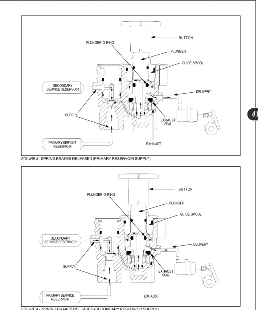
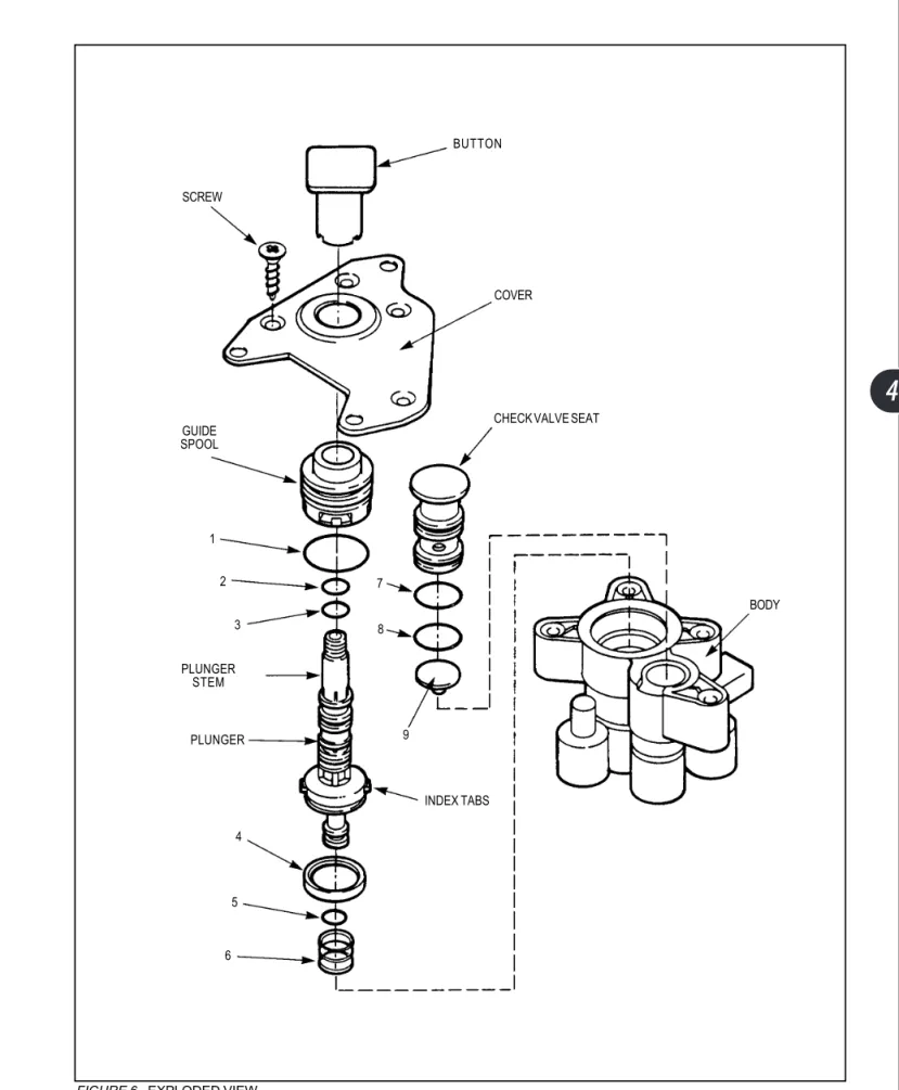
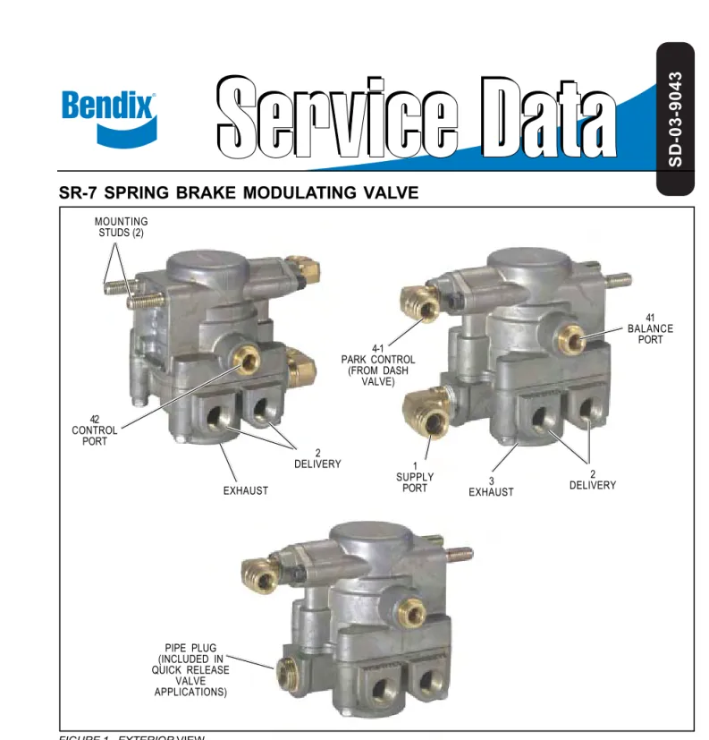
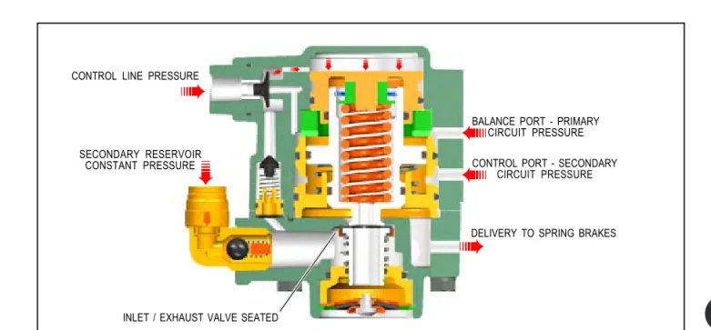
Spring Brake Modulating Valve (SR-7)
The SR-7 spring brake modulating valve controls the op-eration of the spring brakes integrated into the rear brake chambers.In normal driving, with normal operating pressure pres-ent in both primary and secondary circuits, the SR-7’s park control port receives pressure from the delivery side of the PP-DC parking brake valve, signaling the SR-7 that system pressure is operative and to therefore cage (disengage) the spring brakes. In response to the signal pressure, air entering the SR-7’s supply port directly from the secondary tank is al-lowed to pass out the left and right delivery ports to cage the springs.
If secondary circuit air pressure is absent, a single check valve closes the supply port. Control line pressure then be-comes the SR-7’s supply air, and serves to cage the springs.
When the parking brake is applied by the driver, the pressure at the SR-7’s control port is released. The SR-7 responds by closing the supply port pressure coming from the secondary air tank and opening the exhaust port to release air from the spring brake chambers. This provides a quick release of air and a quick and full actuation of the spring brakes.
The balance port on the SR-7 receives signal pressure from a short line leading from the R-12 relay valve. When pressure from this line is absent, indicating a loss of pressure in the primary circuit, the SR-7 goes into its spring brake modulation mode. Variable pressure at the secondary control port is received from a line connected to a tee on the supply side of the front QR-1 valve. As described above in the QR-1 sec-tion, this is the front brake actuating pressure which is adjusted by the E-8P treadle valve. In spring brake modulation mode, the SR-7 valve responds to this variable pressure by proportionally releasing spring brake chamber pressure through the exhaust port. Thus, the spring brakes serve as redundant backup rear brakes in the case of primary circuit pressure being lost. A warning light and buzzer notify the driver of the pressure loss condition. The bus can be safely operated in this mode to drive to a service facility.
The SR-7 also performs an anti-compounding function. That is, it prevents the simultaneous application of full spring brake pressure and service brake pressure to the brake actuating mechanism. When the parking brakes are set, pressure is re-leased from the control port. This causes the SR-7 to release pressure from the spring brake chambers, allowing the springs to actuate the brakes. However, if service brakes are also then applied, pressure from the balance port signals the SR-7 to allow secondary pressure to cage the spring brakes. Thus, when the system is charged, and both parking brake and service brakes are applied, it is actually the service brakes, which are in effect.
359
Inspection & Maintenance
Appendix 8 contains more information on the inner workings of the SR-7 valve, as well as operational and leakage testing. Blue Bird does not recommend disassem-bling or rebuilding the SR-7. If testing determines the valve to be operating incor-rectly, contact your Blue Bird Parts Distributor for a replacement.
Removal
The SR-7 is fastened to its bracket by two mounting studs at the top of the body. 1. Park the bus on a level surface. Stop the engine. Chock all wheels securely to
prevent movement in either direction. Means other than air brakes must be used to prevent vehicle movement. Disconnect the negative terminal of the battery.
2. Open all three tank bleed valves to drain the air brake system to 0 psi. 3. Disconnect the four air lines connected by push-in connectors, at the park
control port, the balance port, the secondary control port, and the supply port.
4. The left and right spring brake hoses are fitted with swivel fittings at their lower ends, where they connect to the brake chambers. Disconnect the hoses at the brake chamber, then at the SR-7.
5. Remove the two self-locking nuts and flat washers from the mounting studs. The SR-7 can now be removed.
Installation
360
ABS Modulator Valves (M-32QR)
In air systems, a modulator valve is more effective when located a short distance from the brake chamber it controls. A Blue Bird Vision equipped with air brakes uses four Bendix M-32QR modulator valves; one located near each wheel.
The front modulators are mounted on the inboard side of the frame rails, just over the front axle. The rear modulators are mounted on either side of the R-12 relay.
The modulators are the final valve assemblies though which air passes on its way to actuate the brake chambers.
Each M-32QR modulator has three ports: a supply port receiving air from the R-12 relay valve (rear) or QR-1 quick release valve (front); a delivery port which sends air to the brake chamber; and an exhaust port on the bottom of the modulator body. The modulator incorporates two electric
solenoids, which control supply and exhaust diaphragms inside the modulator, in response to signals received from the EC-30 control unit during anti-skid braking situations.
Under most normal braking conditions, the modulators are passive, simply through-passing air pressure to the chambers. Similarly, when the brake pedal is re-leased, air moves back through the modulator as it flowed during brake application, and is exhausted at the R-12 relay or QR-1 quick release valve.
If a service brake application is made by the driver, and the ABS system detects an impending wheel lockup, the coils of the two solenoid valve in the affected wheel’s modulator are independently energized or de-energized in a pre-programmed se-quence by the E-30. This is similar in principle to the practice of “pumping the brakes” to prevent wheel skid; however, the ABS system is able to affect the brake application of each wheel independently, with much more accuracy and with a series of high-frequency pulses. The effect is better traction in a wide variety of braking conditions, and more controlled stops.
Inspection & Maintenance
Appendix 9 contains more information on the inner workings of the modulator valves. Blue Bird does not recommend disassembling or rebuilding the M-32QR modulators. If testing determines the valve(s) to be operating incorrectly, contact your Blue Bird Parts Distributor for a replacement.
Removal, Front
Each front modulator is mounted directly to the frame rail by two 5/16” bolts which pass through the body of the modulator and through the frame rail, and are fastened with lock washers and flange nuts on the outboard side of the frame rails.
1. Park the bus on a level surface. Stop the engine. Chock all wheels securely to
M-32 Antilock Modulator Bendix Publication SD-13-4870
361
used to prevent vehicle movement. Disconnect the negative terminal of the battery.
2. Open all three tank bleed valves to drain the air brake system to 0 psi. 3. The brake hose, which leads from the modulator to the brake chamber, is
fit-ted with a swivel fitting at the end connecfit-ted to the modulator. Disconnect the brake hose at this fitting on the outboard side of the frame rail.
4. Remove the two nuts on the outboard side of the frame rail which secure the modulator.
5. Pull the modulator away from the frame rail to more easily access the air lines and electrical connector.
6. Remove the supply line connected to the push-in fitting. Remove the electri-cal connector. The modulator can now be removed.
Installation
Reverse the removal procedure to install the front M-32QR modulator. Tighten the mounting bolts to 80–100 in. lbs. (9–13.5 Nm).
Removal & Installation, Rear
The rear M-32QR modulators are assembled directly to the R-12 valve and mounted as an assembly. See the section above on the R-12 valve for removal & installation procedure.
362
ABS Wheel Speed Sensors (WS-20)
The Bendix WS-20 Antilock wheel speed sensors are electro magnetic devices slip-fitted into mounting sockets on the in-board side of each wheel hub. A notched exciter ring formed with regularly spaced flats rotates with the wheel drum in very close proximity to the sensor. As the flats pass through the sensor’s magnetic field, they AC voltage is generated, the frequency of which is proportional to the speed of the turn-ing wheel. This signal is conveyed electrically through the wiring harness to the ABS Electronic Control Unit.Inspection
Inspect for any visible damage to the sensor, cable, connector, mounting block, and bushing. Replace any damaged components. Appendix 10 contains more informa-tion on the WS-20 wheel speed sensors. Contact your Blue Bird Parts Distributor for a replacement.
Removal, Front
A front wheel speed sensor can be removed without removing the wheel. 1. Park the bus on a level surface. Turn the steering wheel in the direction of the
side of the bus on which you want to remove the sensor. Stop the engine. Apply the parking brake. Disconnect the negative terminal of the battery. 2. Unlatch and raise the hood. Locate the wheel speed sensor by following its
electrical lead
3. Disconnect the sensor lead from the wire harness. Remove the cable ties securing the lead. . Take note of the locations of the ties in order to replace with new ones.
4. Gently pry the sensor out of its socket using needle nose pliers and/or bladed screwdriver. The sensor location is tight, but it can be removed with care. The sensor is not threaded, but friction fitted, so twisting slightly can help removal. Be careful not to damage the wire leads, and do not pull on the leads.
5. The spring clip may remain in the socket, or may pull out with the sensor. Remove the spring clip.
Removal, Rear
Removing a rear wheel speed sensor requires removal of the wheel and brake drum.
WS-20 Wheel Speed Sensors Bendix Publication SD-13-4754
363
1. Park the bus on a level surface with parking brake off. Block the other wheels to prevent the vehicle from moving in either direction.
2. Raise the wheel to be serviced and support the vehicle with safety stands under the frame rails.
3. Remove the tire and wheel assembly. 4. Remove the brake drum.
5. Locate the ABS sensor. Disconnect its electrical leads from the chassis wiring harness and remove the cable ties securing the leads. Take note of the loca-tions of the ties in order to replace with new ones.
6. Gently pull the sensor straight back from its mounting bore. Remove the spring clip.
Installation
Reverse the removal procedures above to install the wheel speed sensors. When inserting the sensors:
1. Install a new spring bushing into the mounting block bore, with the retaining tabs toward the inside.
2. Gently push the sensor all the way into its mounting bore until it contacts the exciter ring. Do not strike the sensor to insert it.
3. Secure the cable leads with cable ties in the locations noted during removal. Inspect to assure that cable leads will not be abraded by contact with other components.
The friction fit of the WS-20 sensors allow them to slide back and forth under force, but retain their position when force is removed. Thus, the sensors self-adjust after being installed. When the sensor is inserted all the way into the mounting block, the hub exciter contacts the sensor, which pushes it back. Normal bearing play will “bump” the sensor away from the exciter. The combination of these two actions will establish a running clearance between the sensor and exciter.
[WARNING] It is important that the wheel bearings be adjusted correctly to ensure that the antilock function does not shut down as a result of excessive wheel endplay.
364
ABS Controller (EC-30)
The ABS Controller is mounted inside the right wall of the bracket supporting the transmission shift control, and is connected to the chassis wiring harness by an 18-pin and a 30-18-pin connector on its bottom side (as mounted on the Blue Bird Vision). The Controller is the “black box” encasing the computer circuitry, which controls the Antilock Braking System. The model used on a Blue Bird Vision equipped with air brakes is the basic configuration Bendix EC-30.
The EC-30 continuously receives and monitors signals from the wheel speed sensors. It analyzes this information during braking to determine when a particular wheel is about to lock up, and thereby loose braking traction. When the EC-30 an-ticipates an impending wheel lock condition, it energizes the supply and/or exhaust diaphragm solenoids in the appropriate M-32QR modulator to “pulse” the brake pressure at that wheel. This maximizes traction and, in most cases, reduces braking distance. When performing ABS braking functions, the ECU also communicates via SAE J1939 serial communications link with the transmission to over-ride torque con-verter lock; necessary for wheel-independent ABS modulation to occur.
The EC-30 controls an ABS warning lamp on the driver’s indicator light panel. On power-up, the light turns on for 2.5 seconds and then turns off. Also at start up, the EC-30 performs a modulator chuff test. With brake pressure applied, the EC-30 acti-vates a chuff at each modulator in the following sequence: right front; left front; right rear; left rear. The chuff sequence is then repeated for a total of 8 chuffs.
Being a sealed electronic unit, the EC-30 is not repairable or rebuildable, but is re-settable; and the EC-30 is itself a diagnostic tool. The EC-30 has a row of LED indicators on its top surface, which reflect the results of simple self-contained di-agnostics. When the EC-30 senses an erroneous system condition, it stores the fault code in memory, activates the appropriate warning lamp and disables all or part of the affected ABS function(s). The faulted component is identified on the EC-30’s diagnostic display.
In most cases, the EC-30 will automatically reset the active fault code when the fault is corrected. However, repeated occurrences of a given fault will cause the fault code to latch. Once the fault code is latched, a manual reset is required. After repair, latched fault codes can be reset by briefly holding a magnet on the reset location of the EC-30 diagnostic display.
For more detailed diagnostics, the EC-30 provides a J1708/J1587 link to com-municate with the vehicle and various diagnostic tools via the Blue Bird Vision’s diagnostic link port located in the driver’s area under the dash, to the left of the steering column.
More detailed information on troubleshooting and diagnosis of the EC-30 and the ABS system is contained in Appendix 11.
365
Removal
The EC-30 is through-bolted to the wall of the bracket supporting the Driver’s trans-mission shifter control. To remove:
1. Park the bus on a level surface. Stop the engine. Apply the parking brake. Disconnect the negative terminal of the battery.
2. Remove the four screws which attach the shifter housing, and remove the housing. Disconnect the 18-pin and 30-pin connectors from the EC-30. 3. Remove the two mounting bolts. The EC-30 can now be removed. Installation
Reverse the removal procedure.
Brake Chambers, Front
MGM Type 20L (2.5” stroke) service brake chambers are used on the front wheels of the Blue Bird Vision. These are non-adjustable, with welded-on clevis ends. Each front brake chamber has one port on the top end of the pressure chamber housing. The hose connected to this fitting leads from the delivery port of the M32QR modulator mounted a short distance away inside the frame rail.
Air entering the chamber acts upon a diaphragm which is connected to a push rod, which extends from the chamber to actu-ate the brakes. The pressure delivered to the chamber, multiplied by the area of the diaphragm results in a significant mechanical advantage gain. Thus, for example, a supply line pressure of 30 psi results in a force of approximately 600 lbs. at the pushrod end.
Inspection
The brake chambers should be visually inspected whenever brake maintenance is scheduled, or at a minimum of every 50.000 miles (80,000 km):
• The brake rod shaft is marked by a bright orange band at its inboard end. With brakes applied, if this band is seen protruding from the brake chamber, it is an indication of excessive push rod extension. The automatic slack adjusters should be inspected for proper operation and/or the brake pads should be inspected for excessive wear.
• Check for any visible signs of cracks in the non-pressure chamber housing around mounting studs.
• Check actuator for leaks around the joint seam between the chamber halves. With brakes applied, spray leak detector solution around the seam.
• The chamber should be replaced if there are any signs of the diaphragm leak-ing or of compressor oil contamination reachleak-ing the diaphragm.
366
[WARNING] Blue Bird does not recommend disassembly or rebuilding of the brake chambers. If a chamber is found to be damaged or suspect, replace it with an identical OEM component.
Removal
The front brake chambers are attached to the chamber bracket of the axle by two self-locking nuts with flat washers. The push rod attaches to the slack adjuster arm by two clevis pins. To remove:
1. Park the bus on a level surface. Stop the engine. Apply Parking Brake. Chock all wheels securely to prevent movement in either direction.
2. Open all three tank bleed valves to drain the air brake system to 0 psi. 3. Disconnect the supply hose at the end connected to the modulator. (This
end has a swivel connector). Then disconnect the hose at the brake chamber end.
4. Remove the two cotter pins and clevis pins, which connect the pushrod to the actuator rod and body of the slack adjuster.
[WARNING] Do not re-use clevis pin retaining clips after removing them. Always replace used clevis pin retainer clips with new ones.
5. Remove the two self-locking nuts and flat washers which mount the brake chamber assembly to the axle bracket. The chamber can now be removed. Installation
To reinstall the brake chamber when no other changes have been made (such as brake shoe replacement) reverse the removal procedure. Tighten the chamber mounting stud nuts to 100–115 ft. lbs. (135.5–156 Nm). Use new clevis pin retain-ing clips. Then check slack adjuster adjustment. (See Slack Adjusters section, below.)
Brake Chambers, Rear
MGM Type 30 brake chambers are used on the rear wheels of the Blue Bird Vision. These are non-adjustable, with welded-on clevis ends. The Type 30 chamber assembly is a combination of two different kinds of brake chambers sharing a common center housing. The lower chamber, from which the pushrod protrudes, is the service brake chamber and operates similarly to the front brake chambers described above. The upper chamber is the spring brake chamber, and contains a powerful coil spring which actuates the brakes
367
two purposes: as normal parking brakes and as a mechanically actuated backup system for rear air brakes.
The service brake and spring brake chambers have separate supply ports. The service brake chamber receives air from the primary tank, as controlled by the R-12 valve and the M-32QR modulator valve. Air entering the service brake chamber acts upon a diaphragm connected to the push rod, which extends from the chamber to actuate the brakes. The pressure delivered to the chamber, multiplied by the area of the diaphragm results in a significant mechanical advantage gain.
The spring brake chamber also contains a diaphragm. However, its supply port receives pressure from the secondary air tank, as controlled by the SR-7 valve. Air entering the spring brake chamber is used not to extend the push rod; but to work against the tension of the coil spring. Whenever air pressure is absent (or released) from the spring brake chamber, the powerful spring tension is applied to the push-rod, actuating the brakes.
It is important to note that the spring brake does not gain mechanical advantage as does the air-powered service brake. Therefore, the captive coil spring is actually strong enough to apply the full force necessary to stop the bus. Even when expanded the full length of its chamber, the spring is still under tremendous compression.
[WARNING] Never attempt to disassemble a spring brake cylinder, even when it contains no compressed air. The spring brake cylinders enclose very powerful coil springs held under high mechanical compression. Any attempt to disas-semble the brake chamber can result in injury or death.
Under normal driving conditions, with the parking brake released and the air system fully charged, the system delivers air to the spring brake chambers, fully compressing (caging) the springs. The spring brakes are held in this disengaged position, and the service brakes perform braking functions.
Whenever the vehicle is stopped and the parking brake is applied, air is released from the spring brake chamber through the SR-7 valve, allowing the spring brakes to fully apply the rear brakes.
If primary circuit pressure is abnormally low or absent, the SR-7 valve varies the air being delivered to the spring brake chamber in response to the driver’s operation of the brake pedal. This condition, called “spring brake modulation,” allows the spring brakes to function as rear brakes while driving the bus.
If both primary and secondary system pressure fail (or if system pressure is not yet charged, as at the beginning of service), no pressure is available to cage the spring brakes. The spring brakes fully apply, preventing the vehicle from being driven until proper air brake operation is restored.
Manual Spring Brake Disengagement
Means are provided on the spring brake chambers by which to manually disengage the spring brakes so as to allow the bus to be towed for repair in an emergency situ-ation; or to allow the rear brake components to be serviced without the air system being charged.
368
On each of the rear combination brake chambers, a special tool is carried in a storage socket cast into the body of the chamber. The tool consists of a release bolt with a specially formed end, a washer, and hex nut. To manually disengage the spring brakes for service:
1. Stop the engine. Chock all wheels to prevent movement in either direction. Use whatever means necessary to make absolutely certain the bus cannot roll when the spring brakes are released.
[WARNING] Do not manually disengage spring brakes if the vehicle is in an unstable roadside situation, or if the vehicle can roll when the spring brakes are released. Movement of the bus must be prevented by means other than brakes.
2. Open all three tank bleed valves to drain the air brake system to 0 psi. 3. Remove the nut and washer from the end of the release bolt, and remove the
tool from its storage socket.
4. Remove the rubber dust cap from the access hole in the upper end of the spring brake chamber.
5. Insert the toggle end of the release bolt into the access hole. Be sure that the formed end of the release bolt has entered the hole in the piston inside the chamber. Continue to insert the bolt until it bottoms out.
6. Turn the release bolt ¼ turn clockwise and pull outward on the bolt to lock the formed end into the piston.
7. Holding the bolt locked into the piston, install the flat washer and the release nut onto the end of the release bolt, and turn down the nut against the flat washer until finger tight.
8. Using a ¾” hand wrench (do not use an impact-type wrench), turn the re-lease nut clockwise until the internal spring is fully caged.
9. Repeat this procedure for the spring brake chamber on the opposite side of the bus. The spring brakes are now released, having their springs com-pressed by the release bolts.
Inspection
The brake chambers should be visually inspected whenever brake maintenance is scheduled, or at a minimum of every 50.000 miles (80,000 km):
369
an indication of excessive push rod extension. The automatic slack adjusters should be inspected for proper operation and/or the brake pads should be inspected for excessive wear.
• Check for any visible signs of cracks in the non-pressure chamber housing around mounting studs.
• Check actuator for leaks around the joint seam between the chamber halves. With brakes applied, spray leak detector solution around the seam.
• The chamber should be replaced if there are any signs of the diaphragm leak-ing or of compressor oil contamination reachleak-ing the diaphragm.
[WARNING] Never attempt to disassemble or rebuild the rear brake cham-bers. If a chamber is found to be damaged or suspect, replace it with an identi-cal OEM component.
Removal
The rear combination brake chambers are attached to the chamber bracket of the axle by two self-locking nuts with flat washers. The push rod attaches to the slack adjuster arm by two clevis pins. To remove:
1. Park the bus on a level surface. Stop the engine. Chock all wheels securely to prevent movement in either direction. Means other than brakes must be used to prevent vehicle movement.
2. Open all three tank bleed valves to drain the air brake system to 0 psi. 3. Manually disengage the spring brake being removed as described above in
Manual Spring Brake Disengagement.
4. Disconnect both supply hoses from the brake chamber supply ports. 5. Remove the two cotter pins and clevis pins which connect the pushrod to the
actuator rod and body of the slack adjuster.
[WARNING] Do not re-use clevis pin retaining clips after removing them. Always replace used clevis pin retainer clips with new ones.
6. Remove the two self-locking nuts and flat washers which mount the brake chamber assembly to the axle bracket. The chamber can now be removed. Installation
To reinstall the brake chamber when no other changes have been made (such as brake shoe replacement) reverse the removal procedure. Tighten the chamber mounting stud nuts to 100–115 ft. lbs. (135.5–156 Nm). Use new clevis pin retain-ing clips. Then check slack adjuster adjustment. (See Slack Adjusters section, below.)
370
Slack Adjusters
At each wheel, the brake actuating push rod of the air brake chamber connects to an automatic slack adjuster mecha-nism, which acts as a lever to turn the brake assembly’s S-cam shaft.
As the friction surfaces of the brake shoes wear, they grow thinner, and the clearance between the brake shoes and drum increases. If this situation were left uncorrected, the brake chamber push rod would have to travel an ever-increasing distance in order to actuate the brakes and fre-quent manual adjustment would be necessary to remove this excess travel. The role of the automatic slack adjuster is to compensate for the brake shoe wear by acting as a ratch-eting mechanism, much like a ratchet wrench, keeping the linkage travel within normal tolerance.
Meritor slack adjusters are standard on the Blue Bird Vision. Haldex adjusters are on some units as an option. The two types perform the same function, but by some-what different internal mechanisms.
In Meritor slack adjustors, the ratcheting function is performed by a pawl which engages the notches of a toothed adjusting sleeve which rotates as brake lining wear occurs. The spring-loaded pawl can be manually released by pulling a button on the outside of the slack adjuster body.
On Haldex adjusters, the internal ratcheting action is performed by a one-way clutch on the shaft of a worm drive gear which rotates as brake lining wear occurs.
Appendix 12 contains more detailed information on the Meritor automatic slack adjusters. Appendix 13 contains more detailed information on the Haldex automatic slack adjusters.
Adjustment
The slack adjusters on the Blue Bird Vision are designed to be self-adjusting. The only times at which manual adjustment should be necessary is when initially setting the adjusters after reassembling the brakes following service procedures such as shoe replacement. If brake travel is found to be out of range, always be sure to find the root cause. Making manual adjustments of the slack adjusters is probably only affect-ing a symptom, and not correctaffect-ing the actual cause of a problem.
Thorough instructions for making the initial slack adjuster settings after servic-ing the brakes are contained in the two appendixes mentioned above.
Removal of Meritor Slack Adjusters
Meritor slack adjusters are mounted on the splined shaft of the S-cam, and secured by an outer diameter circlip. The end of the actuating arm is connected to the brake chamber push rod clevis by two clevis pins and clevis pin retainer clips. To remove: