CHAPTER 21
GEOTECHNICAL ASPECTS OF
PIPE DESIGN AND INSTALLATION
21.1 OVERVIEW ... 21-5 21.2 EFFECTS OF LOADS ON BURIED PIPES ... 21-5 21.2.1 Types of Load ... 21-5 21.2.1.1 Dead Load ... 21-5 21.2.1.2 Live Load ... 21-6 21.2.2 Types of Pipe ... 21-7 21.2.2.1 Flexible Pipe ... 21-8 21.2.2.2 Rigid Pipe... 21-9 21.2.3 Transmission of Load... 21-10 21.2.4 Pipe Reaction to Load ... 21-11 21.2.4.1 Flexible Pipe ... 21-11 21.2.4.2 Rigid Pipe... 21-12 21.2.5 Importance of Side Support ... 21-12 21.2.6 Effect of Ditch Width ... 21-15 21.2.6.1 Use of Controlled Low Strength Material as Pipe Backfill ... 21-16 21.2.7 Bedding ... 21-17 21.2.8 Effects of Improper Compaction on Pavement over Pipe ... 21-19 21.2.8.1 Flexible Pipe ... 21-19 21.2.8.2 Rigid Pipe... 21-20 21.2.9 Effects of Improper Removal of Sheeting ... 21-21 21.2.10 Effects of Construction Loads ... 21-21 21.2.11 Infiltration of Material ... 21-22 21.3 PIPE CULVERT DESIGN ... 21-24 21.3.1 Rigid Pipe... 21-25 21.3.2 Flexible Pipe ... 21-27 21.3.2.1 Modulus of Soil Reaction, E' ... 21-29 21.3.3 Non-Standard Pipe Installations... 21-33
21.3.3.1 Pipe Culverts Placed Under Very Shallow Soil Cover or Below
Concentrated Surcharge Loads ... 21-33 21.3.3.2 General Discussion on Pipes Placed Under Very High Fills ... 21-33 21.3.3.3 Adverse Foundation Conditions for Pipe Culverts ... 21-34 21.3.3.4 Existing Pipe Culverts Crossed by New Fills ... 21-34 21.3.4 Ensuring Long Term Structural Capacity of Corrugated Metal Pipe ... 21-35 21.3.4.1 Example Calculation ... 21-38 21.4 INSTALLATION TECHNIQUES ... 21-40
21.4.2.1.2 Slurry Boring (SB) ... 21-44 21.4.2.1.3 Pipe Jacking (PJ) ... 21-44 21.4.2.1.4 Microtunneling (MT) ... 21-45 21.4.2.1.5 Horizontal Directional Drilling (HDD)... 21-45 21.4.2.1.6 Utility Tunneling (UT) ... 21-46 21.4.2.2 Design Development ... 21-46 21.4.2.3 Construction Operations ... 21-52 21.5 REFERENCES ... 21-53
21.1 OVERVIEW
Highway drainage and utility installations require the design, placement and backfilling of conduits to support the facilities and ensure adequate performance of the Department’s roadway system. A properly designed pipe may fail due to inadequate or inappropriate installation
techniques. Therefore, the importance of the Inspector’s attention to detail during the placement and backfilling operations is stressed throughout this Chapter.
21.2* EFFECTS OF LOADS ON BURIED PIPES
*The following discussion in Section 21.2 Effects of Loads on Buried Pipes is adapted (with modifications) from the Department of Army, Corps of Engineers, January 1960.
Buried pipes serve two functions: hydraulic and structural. They must provide a passage for the fluid for which they are designed and equally important, they must fit the surrounding ground, supporting the weight of the ground and any load on it.
Unless the pipe is properly installed, it can cause serious problems not only to itself but to pavements, buildings, other structures, and equipment. Therefore, a pipe is not to be buried and forgotten, it must be carefully made and installed.
21.2.1 Types of Load
Pipes must support the loads resulting form the dead weight of the overlying soil and, in addition, must carry any added live and static loading passed down to them through this overlying soil from loads applied on the ground surface.
The Designer must provide an installation of sufficient strength to accommodate the loadings that will be delivered to the pipe, and the Inspector must assure that the Designer’s requirements are fulfilled during construction so that a satisfactory installation will result.
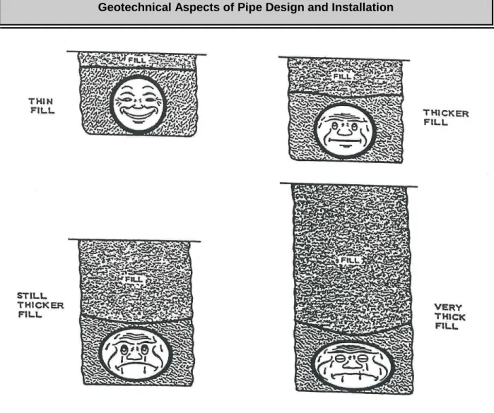
21.2.1.1 Dead Load
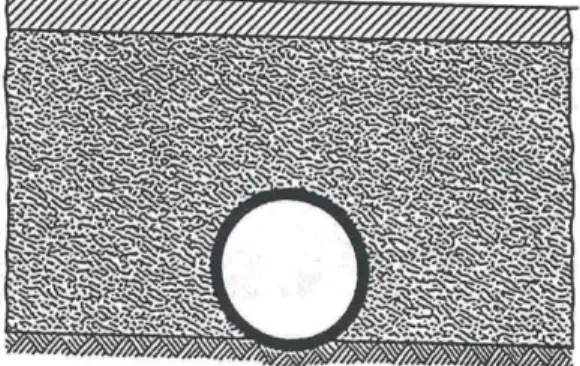
High fills increase the probability of dead load problems (see Figure 21-1). As the fill height is increased, the weight of the soil supported by a buried pipe is likewise increased.
Figure 21-1 Pipe Action Under Dead Load
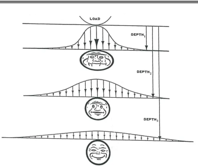
21.2.1.2 Live Load
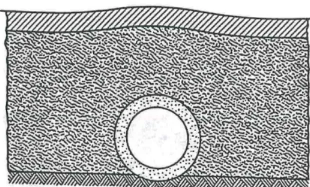
These loads are applied to a limited area of the surface over a buried pipe (e.g. through the contact area of a tire or crawler track). As the effect of this load progresses downward into the soil, the area over which it is effective grows larger and since the total load is fixed, the pressure or load intensity is diminished (see Figure 21-2). Thus a deeply buried pipe is usually subjected to a lower intensity of loading from a surface load than a shallow-covered pipe. Design tables for maximum allowable soil cover often include a surcharge load to represent traffic or construction loadings.
Figure 21-2 Pipe Action Under Live Load 21.2.2 Types of Pipe
Pipe types in common use fall fairly neatly into two groups:
• Flexible – represented primarily by corrugated metal and plastic pipe, and
• Rigid – represented primarily by reinforced concrete pipe but also includes plain concrete and clay pipe.
Cast iron, non-corrugated steel, transite, and fiber pipe are also found in less common use or in special purpose applications. These range in strength and flexibility and do not neatly fit into either grouping, each must be considered in the light of its individual characteristics.
21.2.2.1 Flexible Pipe
Pipe is called flexible when the material of which it is made can be flexed or bent. It obtains its ability to support vertical loads almost entirely from the backfill material adjacent to its sides. If, because of poor design or installation practices, such a pipe receives inadequate side support from the backfill, it generally does not fail by a break or facture but by deflecting to such a degree that it will either no longer carry the necessary flow or no longer support the ground above it in a satisfactory way (see figure 21-3). However, it should be noted that, with large deflections of flexible pipe, structural buckling becomes a greater possibility, which will occur suddenly when critical loads or deflections are reached. Commonly, a 5% decrease in mean vertical diameter of a buried pipe is considered permissible. It has been established however, that about a 20% change in vertical diameter can occur prior to complete collapse.
21.2.2.2 Rigid Pipe
Rigid pipe has significant inherent strength to support loads without aid from the backfill. However, its load-carrying capacity can be increased by a factor of 4 or more by taking special measures in bedding and backfilling the pipe. Rigid pipe fails by breaking or fracturing before deflections have become appreciably large (see Figure 21-4). Unreinforced rigid pipe, such as clay or plain concrete, is commonly considered to be failed when it has cracked or fractured. However, in reinforced concrete pipe the appearance of a crack as wide as a 0.01 in. is commonly considered permissible. A crack, without collapse of the pipe, obviously does not prevent rigid pipe from serving as a conduit, yet it does represent a loss in strength of a non-reinforced pipe and possible exposure of the reinforcing steel by wide cracks in reinforced pipe.
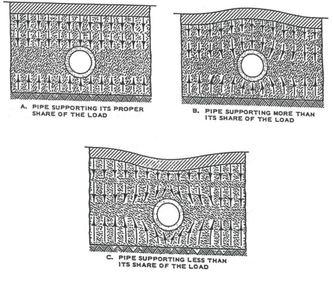
21.2.3 Transmission of Load
Loads applied to a soil mass are transmitted downward through it along regular, smoothly flowing paths or lines. Loads applied to small areas are transmitted downward and outward from the center of the load with intensities decreasing as the spreading increases. Broad loads, such as embankments, applied over wide areas are transmitted vertically downward along generally parallel paths with slowly diminishing intensities. When it is necessary to place an object such as a pipe in otherwise continuous soil, it will receive what might be considered as its proper share of the load only if it does not significantly change the pattern of load distribution within the soil medium (See Figure 21-5 A.). A pipe which is more rigid than the surrounding soil will stiffly accept more than its fair share of the load and cause the soil beside the pipe to be less heavily loaded (See Figure 21-5 B.). A pipe able to compress more than the surrounding soil will yield, or “shed”, some of the superimposed load to the soil beside it (See Figure 21-5 C.).
21.2.4 Pipe Reaction to Load
The soil in which a pipe is to be installed has its own stiffness or resistance to vertical deflection under a surface load. A wheel load on the surface, for instance causes the soil beneath it to be compressed and produce a measurable depression. If a pipe is present within this compressed mass of soil, it will also be compressed.
21.2.4.1 Flexible Pipe
Pipe of this type is ordinarily less stiff (more flexible) than the soil in which it is embedded. Thus, as Figure 21-6 shows, the tendency is for the pipe to be deflected vertically (i.e. top and bottom flattened), more than the adjacent soil. This, in turn, tends to cause an increase in
horizontal diameter of the pipe, which can only occur through compression of the soil beside the pipe. Good compaction beside the pipe during installation will minimize the effect.
Figure 21-6 Flexible Pipe, Generally Less Stiff Than Adjacent Soil
21.2.4.2 Rigid Pipe
Pipe of this type is ordinarily more stiff than the soil in which it is embedded. Thus, as Figure 21-7 illustrates, the tendency is for the pipe to be deflected vertically less than the adjacent soil. This, in severe cases, leads to a hump over the pipe or low places on either side of it, and also results in the pipe carrying more than its proper share of the load from above. Here again, good compaction beside the pipe during installation will minimize the effect.
Figure 21-7 Rigid Pipe, Generally Stiffer Than Adjacent Soil
The Designer ordinarily assumes that the soil surrounding the pipe has a density and therefore a stiffness at least as great as the undisturbed adjacent soil. The Inspector must insure that adequate density is obtained otherwise failures will result.
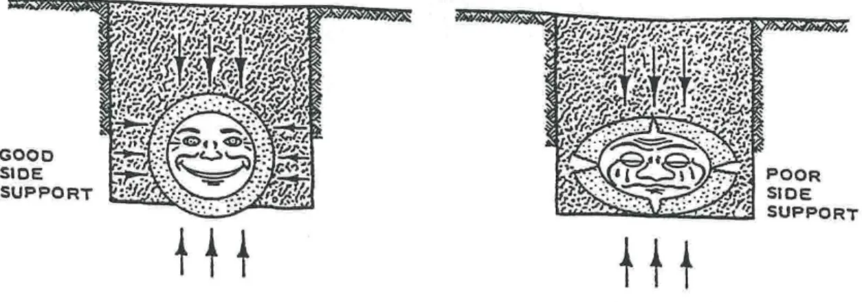
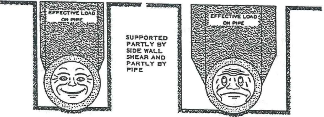
21.2.5 Importance of Side Support
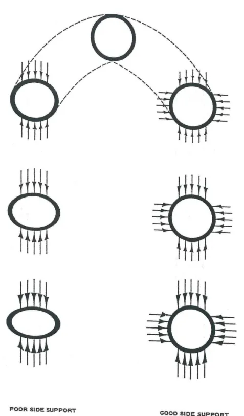
If the vertical diameter of a circle of fixed circumferences is shortened, its horizontal diameter is lengthened. It follows then that the support which tends to prevent the lengthening of the
horizontal diameter of a circular pipe will resist loads tending to shorten its vertical diameter. Flexible pipe, while easily deformed by bending, is quite rigid with respect to retaining the length of its circumference. Given good side support, it is capable of sustaining great vertical loads (See Figure 21-8).
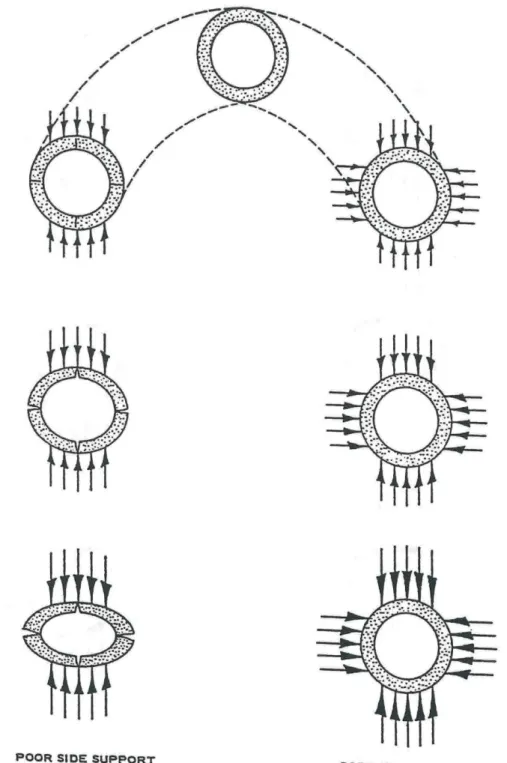
Rigid pipe, while capable of carrying larger loads without side support, it limited by it inherent strength. The addition of side support increases its vertical load-carrying capacity. The need for side support, while more obvious and extremely important for flexible pipe, can be quite important for rigid pipe also (See Figure 21-9).
21.2.6 Effect of Ditch Width
Ditches must be carefully backfilled in order to regain the stability originally present in the soil. Even in pipe installations where fairly good replacement of the material is achieved, voids or zones of poor compaction may be left under the haunches of the pipe, in the corrugations of metal pipe, or in bell holes of bell-and-spigot pipe. This can result in loss of vertical support within the ditch adjacent to the pipe. When this occurs, the weight of the backfill, which should be carried by material in the ditch beside the pipe, must be carried jointly by the pipe and the undisturbed soil beside the ditch. The narrower the ditch in which the pipe is laid, the less extra weight the pipe will receive (See Figure 21-10).
Figure 21-10 Narrow Ditch Leads to Less Pipe Load
The pipe shares load with the undisturbed soil beside it, thus making ditch width important. However, above the top of the pipe, load is transferred to disturbed fill as readily as to the undisturbed ditch wall (See Figure 21-11). The control of ditch width is therefore generally essential only to or a little above the top of the pipe.
Figure 21-11 Width of Ditch Above Top of Pipe is Not Critical
In specifying ditch widths, the Designer must recognize that adequate working space must be provided. Good compaction beside and beneath the haunches of a pipe cannot be gained if working space is too limited. NYSDOT practice is to specify a minimum trench width so that the backfill can be properly compacted and to neglect the effect of trench width on the load reaching the pipe.
21.2.6.1 Use of Controlled Low Strength Material as Pipe Backfill
Controlled Low Strength Material (CLSM) is a fill material mixture that consists of cement, water and, when appropriate, fly ash, aggregate, or chemical admixtures such that the final product displays a low compressive strength after curing and a large spread capability prior to setting. The material can be produced on site or at a concrete plant and delivered by truck. The mix is proportioned to be self leveling and does not require compaction. After it has set, which usually occurs within two hours after placement, CLSM displays the characteristics of compact, undisturbed soil, but it is susceptible to deterioration if exposed to freezing conditions.
CLSM is used as a replacement for soil backfill in sites where adequate compaction of the
backfill is difficult to achieve or may be too time consuming. In addition to being used as backfill around pipes and drainage structures, CLSM is used as backfill behind abutments, around thrust blocks, or as a cut-off for subsurface water flow. Due to its large spread capability and quick setting, it may be used for excavations that require immediate backfilling or for backfilling narrow excavations where access by construction personnel is dangerous or impractical. Standard Sheet 204-01 Controlled Low Strength Material (CLSM) Installation Details for Circular and Elliptical Corrugated Metal Pipes, Structural Plate Pipes and Pipe Arches, and Reinforced Concrete and Other “Rigid” Pipes provides installation details.
21.2.7 Bedding
The load delivered to a pipe from above, whether it be the weight of the overlying soil or some surface load, must in turn be delivered by the pipe to the underlying soil. If firm support of the pipe by underlying soil is established only over a narrow width, as with a round pipe in a flat-bottom trench, the intensity of the load (stress) beneath the pipe will be large and failure is more likely. Some means of establishing firm support of the pipe over a wider band will reduce the load intensity beneath the pipe and consequently the likelihood of failure (See Figure 21-12).
Figure 21-12 Effect of Bedding
This same effect magnified several times can occur with bell-and-spigot pipe if it is placed without cutouts for the bells (See Figure 21-13).
Figure 21-13 Pipe Installed With and Without Cutouts for Bells
Rock foundations are particularly critical in regard to load concentration, and an earth cushion must be provided to promote distribution of the load between the bottom of the pipe and the bedrock (See Figure 21-14).
Figure 21-14 Pipe Installed on Rock
Figure 21-15 Proper and Improper Support Conditions
21.2.8 Effects of Improper Compaction on Pavement over Pipe
It is possible for flexible pipe to be appreciably deflected and still carry most of its design flow. It is also possible for rigid pipe to accept the overloading which results from inadequate
compaction of the side fill, in many cases without failure, and nearly always without failure to such a degree as to significantly decrease its flow capacity. But these conditions cannot be tolerated in overlying pavements, because the settlements that result cause pavement failures.
21.2.8.1 Flexible Pipe
Figure 21-16 Effect of Improper Compaction in Embankments
21.2.8.2 Rigid Pipe
Greater settlement of backfill adjacent, rather than over, rigid pipe after construction of the overlying pavement leads to loss of pavement support on either side of the pipe with resultant pavement failure (See Figure 21-16).
Although two types of action leading to failure are involved here, the preventive measures are the same for both. The Inspector must see that good compaction is accomplished beside and over the pipe. In each case, this means more uniform pavement support.
21.2.9 Effects of Improper Removal of Sheeting
If the side support essential to nearly all pipe installations is to be gained, it is obvious that there can be no voids beside the pipe. Accordingly, the volume once occupied by sheeting which has been pulled must be filled with properly compacted material (See Figure 21-17).
Figure 21-17 Effect of Improper Removal of Sheeting
Inspectors must insure that the sheeting is removed in such a way that any resulting voids can be eliminated and the backfill and compaction procedures are such as to insure their elimination. 21.2.10 Effects of Construction Loads
Pipe installations are designed for the loads they are to support after completion of construction. Heavy construction loads permitted of a pipe before its installation is complete could be very injurious. Such loadings before completion should be avoided unless special precautions are taken. Use of extra strong pipe, placement of timbers as bridging to spread the load, or increasing the fill height above the pipe at crossings are precautions which can be taken.
21.2.11 Infiltration of Material
Unless special measures are taken during manufacture and installation, storm drains, sanitary sewers, and culverts are not normally watertight over the full life of the pipeline. Since some these pipelines are designed to disperse storm runoff or sanitary waste water through gravity flow, there will be periods during which flow is low. In many places the pipelines will be partly or entirely below the groundwater table, resulting in seepage of groundwater from the
surrounding soils through the pipe joints or other openings into the pipeline (See Figure 21-18). Also, pipelines which use pressurized flow can create a suction effect at minor cracks or
openings. This infiltration of groundwater is of great importance when it carries fine-grained soil particles from the backfill into the pipe. The loss in backfill reduces the side support of the pipe, lowers the discharge capacity of the drainage facilities by obstructing the lines with soils, and in extreme cases creates large voids beside and over the pipe. This can result in undermining of airfield or road pavements and any there overlying structures. When this condition develops, it is difficult and costly to remedy.
One, or more, of several conditions must be present for infiltration of material into a pipe to result. These are:
• High water table,
• Backfill material containing fine particles that can be moved by percolating water (piping). Coarse silts and fine sands are the worst offenders, and
• Gaps at pipe joints, or cracks of sufficient size to permit entrance of material carried or moved by seepage or suction.
When the first two conditions appear to be present, great care should be taken with all joints and alignment, and special joint treatments should be considered. Pipe backfill consisting of coarse sand or small aggregates may also be considered.
Designers must be on the lookout for the combinations of conditions that can lead to infiltration and take special precautions against them. Consideration should be given to seasonal or other changes in groundwater levels which may result in more severe conditions than found at the time of field design explorations.
Perforations
In instances where perforations (holes) or slots are incorporated into pipes, the pipe must be embedded within a filter designed to prevent movement of the surrounding soil into the pipe. Criteria have been developed for the determination of the required grain size of a granular filter material – see NYSDOT GDM Chapter 20.
21.3 PIPE CULVERT DESIGN
The design process first involves a determination of the acceptable options for the flow cross-section required for either rigid or flexible types of pipe by considering hydraulic factors. The structural analysis of the pipe then follows and this must take into account the site requirements for fill height, steep slopes or surcharges, p ipe bedding conditions, and structural durability.
The design process for the standard placement (i.e. placed within compacted backfill) of a large range of pipe sizes consisting of various structural materials (reinforced concrete, corrugated metal, or corrugated polyethylene pipe) has been reduced by the Department to its simplest form, (i.e., Allowable Height of Fill tables). These fill height tables encompass all the standard installation conditions which are normally encountered in the field.
On New York highway projects, two bedding types are considered to be consistently attainable in the field using reasonable procedures with varying qualities of inspection. These are "Ordinary Soil Bedding" and "Concrete Cradle Bedding".
21.3.1 Rigid Pipe
In the design of rigid pipe installations (concrete, clay, or reinforced concrete), only two design analysis loading conditions, the “positive projection” and the “imperfect trench” conditions, are found to be necessary to address each type of pipe bedding condition and installation commonly used.
• The “positive projection” soil load condition assumes a pipe is installed within a compacted embankment fill, or that the pipe is installed in a trench with a sufficient width that creates conditions equivalent to a compacted embankment fill. All the standard details for rigid pipe installation will allow the use of the “positive projection” soil load condition on the pipe. Even the Department’s standard detail for pipe installation with CLSM backfill and a reduced trench width assumes a “positive projection” soil load condition.
• The “imperfect trench” design analysis is applied to a trench installation which incorporates a layer of compressible material within the backfill directly above the pipe (not commonly used). The compressible layer allows a reduction of the earth loading on the pipe. Refer to the design manual by the American Concrete Pipe Association or the ASCE design guidance ASCE 15-98 for additional information. “Negative projection” soil load conditions (i.e. pipes installed in a trench below the base of an embankment) and “trench” soil load conditions (i.e. moderate to narrow trench widths placed below an existing ground surface) are very seldom utilized in a rigid pipe design analysis because standard pipe installation details use an excavation width that is too wide for these soil load conditions to fully develop. Secondly, use of the “positive projection” load condition for trench installations results in a conservative pipe loading analysis and also accounts for improper removal of sheeting from the excavation. Third, use of “trench” or “negative projection” soil load conditions requires the backfill within the trench excavation to settle more than the in-situ soil on the sides of the trench. While this scenario may reduce the soil load on the pipe, it may also lead to settlement at the road surface.
A type of rigid pipe installation, which the Department commonly utilizes, that can result in a significant reduction of the soil loads on the pipe is the jacked or tunneled pipe installation. If the soil where the pipe will be installed is not loose, weak, or contains normally consolidated clay, and the jacked pipe will be located permanently above the water table and in a granular soil with a medium to high relative density, then a reduced soil loading can be anticipated. If any one of these subsurface conditions cannot be met, then the rigid pipe should be designed using a “positive projection” soil load condition. Refer to the design manual by the American Concrete Pipe Association for additional information.
Indirect Design Method and the Direct Design Method. The Indirect Design Method is described in AASHTO Stand Specification For Highway Bridges, the design manual for the American Concrete Pipe Association, and the ASCE design guidance ASCE 15-98. The Direct Design Method is discussed in ASCE design guidance ASCE 15-98 for standard installations, in ASCE 27-00 for jacked installations, and in the FHWA manual (1983) on “Structural Design Manual for Improved Inlets and Culverts”.
The Indirect Design Method is most commonly used by designers and it is based on a simplified method of determining a design load value (D-Load) for a chosen pipe size and installation condition. This design load value is then compared to the five strength class ranges established for reinforced concrete pipes. The range of design load values (D-Load) for each reinforced concrete pipe strength class is provided in Table 21-1.
Pipe Strength Class D-Load Value Range Class I < 800 lbs/ft/ft
Class II < 1000 lbs/ft/ft Class III < 1350 lbs/ft/ft Class IV < 2000 lbs/ft/ft Class V < 3000 lbs/ft/ft
Table 21-1 Concrete Pipe Strength Class
The designer only needs to choose the appropriate pipe strength class for the D-Load value calculated as per the site conditions. The strength class will determine the required
reinforcement and minimum wall thickness of the concrete pipe as listed in ASTM C76. The Direct Design Method is generally only used to design reinforced concrete pipes for non-typical or extreme installation conditions, such as very large soil loads, large point, jacking, or surcharge loads, or for pipe sizes that are too large to utilize the D-Load value tables. The design method establishes the reinforcement, wall thickness, and concrete strength of the required pipe. Typically, a soil pressure diagram around the pipe is produced and the critical moment, shear, and thrust values in the pipe wall are then obtained. Various empirical methods and computer programs have been developed to determine these values more easily. Refer to the Direct Design procedure described in the design guide ASCE 15-98 or the FHWA manual (1983) on “Structural Design Manual for Improved Inlets and Culverts.” For an overly conservative structural design of a jacked reinforced concrete pipe, use a pipe with a Class V strength and a C-wall thickness. The procedure for a detailed structural analysis on a jacked pipe can be found in the design guidance ACSE 27-00.
For reinforced concrete pipe, a safety factor of 1.0 on the first crack strength and a soil unit weight of 125 lbs/ft3 are typically used for the pipe’s structural analysis.
NYSDOT’s Allowable Height Of Fill tables for all field installation conditions, i.e. conditions such as embankment and trench (i.e. wide trench condition) were established by assuming values for settlement ratio and load factor and making other appropriate inputs into the load analysis formulas. The designer, using these tables (included in Chapter 8 of the NYSDOT Highway Design Manual) needs only to select the appropriate pipe strength class, backfill type, and installation method combination which most economically satisfies the field condition.
The key aspects involved in coordinating construction practice to design include standards for bedding, backfill materials, compaction requirements, minimum temporary and final cover and construction procedures. This construction coordination to design is accomplished as detailed on Standard Sheet 203-04 Installation Details for Reinforced Concrete Pipes which becomes part of the plans and specifications whenever rigid pipe is used. Bedding details are shown which include additional procedures to be used by the Engineer in the field as necessary to prepare the foundation. For example, rock foundations are required to be undercut below invert to as much as ¾ of the pipe diameter, and temporarily unstable, wet soil is replaced during the bedding process. Installation details are also shown for the trench and two conditions of embankment installation; one for placing the pipe before filling and the other building the fill to partial height and excavating a trench for pipe placement. All pipes after bedding, whether in cut or fill, are backfilled with a specified type of granular material placed to minimum established limits and compacted to at least 95% of the maximum density as determined by AASHTO Designation: T-99, Method C.
Durability design for rigid pipe must not be completely overlooked although it is not as significant a consideration as for flexible types. Agricultural and industrial waste or mine tailings may dictate that a different pipe material be used.
21.3.2 Flexible Pipe
NYSDOT’s “Allowable Height Of Fill” tables for flexible metal pipes provide the appropriate structural characteristics (i.e. wall gauge and corrugation pattern) for various pipe diameters, maximum allowable soil cover, and pipe materials. The “Allowable Height Of Fill” table for corrugated polyethylene pipe establishes only one maximum allowable soil cover for all pipe diameters and does not account for changes in the structural characteristics of the plastic pipes. If the NYSDOT’s design tables do not provide the appropriate pipe design for the site conditions, a detailed analysis will be required.
Design of Flexible pipe in common use falls into two broad classifications:
• Corrugated Metal Pipe – design criteria are based on the Service Load Design Method in Section 12 of the current AASHTO Standard Specifications for Highway Bridges as modified by NYSDOT and included in Chapter 8 of the NYSDOT Highway Design
• Thermoplastic Pipe – designed in accordance with the Service Load Design Method in Section 18 of the current AASHTO Standard Specification for Highway Bridges as modified by NYSDOT.
Experience in New York highway work has shown that deflections of flexible metal pipes have been insignificant, i.e. generally much les than the usual 5% criterion. This very favorable deflection performance is related to the low compressibility of the surrounding backfill, and therefore, attributable to the installation methods used. Yet, this ability for the pipe to deflect also allows the soil pressures on the pipe to be more evenly distributed around the pipe and thereby reduce the effects of any concentrated or very heavy soil loads on the pipe. This has led to the elimination of elongation and strutting as a design consideration and construction requirement. The design of flexible pipe culverts must take into account the Design Life and the Service Life of the structure. The “design life” is defined as the minimum number of years the pipe must function properly as required by the site conditions. The “service life” is the number of years that the pipe is anticipated to function properly before excessive deterioration occurs at the pipe invert or walls. A properly designed flexible pipe must ensure that the “service life” of the pipe can match or exceed the number years for the pipe’s “design life”.
Corrosion and abrasive flows, the major causes of metal loss, are the factors that typically limit the service life of corrugated steel pipe. The metal loss rates for galvanized steel pipe in various locations throughout New York State have been studied by the NYSDOT. Based on these
studies, the NYSDOT’s Highway Design Manual provides a table showing anticipated metal loss rates for several geographic locations. The table separates these locations into two groups:
• Zone 1 with a metal loss rate of 2 mils/yr, and • Zone 2 with a metal loss rate of 4 mils/yr.
The Highway Design Manual (HDM) provides a second table which gives the anticipated service life for steel pipes with various wall gauges, types of additional protective wall coatings, and invert linings.
As can be seen on the second HDM table mentioned above, the service life for steel pipe can be extended by using wall coatings and/or by paving either at the invert or along the full inner perimeter of the pipe. Methods used by NYSDOT to calculate the service life of steel pipe under various conditions and by incorporating various types of protective treatment have been evolving over the years. The current method is described in Chapter 8 of the NYSDOT Highway Design Manual.
Due to the lack of corrosion, the factors limiting the service life for aluminum material are
different from those for steel pipe. Therefore, for all aluminum pipe, the anticipated service life is currently anticipated as 70 years. The NYSDOT’s “Maximum Allowable Height of Cover” tables covers aluminum pipe with 2⅔ x ½ in. and 3 x 1 in. corrugation styles. This interim approach which is based on much more limited data does not necessarily imply that the durability of aluminum is of no concern especially since a recent finding at a few sites in New York
The durability of thermoplastic pipe is taken into account in selecting the design strength and modulus for pipe of various cell classes as given in Section 18 of the current AASHTO Standard Specifications for Highway Bridges. As a minimum, the NYSDOT’s Highway Design Manual currently assumes a service life of 70 years for thermoplastic pipe.
Installation requirements and procedures for flexible pipe are also presented on Standard Sheet 203-05 Installation Details for Corrugated and Structural Plate Pipe and Pipe Arches which is made part of the plans when this type of pipe is used. This drawing shows only Ordinary Bedding including treatment of an unstable soil foundation and rock undercut as well as a trench (sheeted or open cut) and two embankment methods of installation similar to those for rigid pile. Backfill and compaction criteria are also similar to rigid pipe standards
21.3.2.1 Modulus of Soil Reaction, E’
The performance of flexible pipe in its ability to support load is typically assessed by measuring the deflection from its initial shape. Deflection was historically ignored as metal pipe used riveted seams, which typically controlled the design. However, pipe produced today use thinner materials. Therefore, deflection assessment allows a measurable quantity to be compared with design values. This deflection assessment is helpful twofold
• It controls the design limitation on flexible pipe, and
• Aids in identifying structural problems associated with other performance criteria. Merlin Spangler (1941) published The Structural Design of Flexible Pipe Culverts, in which he derived an equation for predicting the ring deflection of buried flexible pipes known as the Iowa Formula. Reynold Watkins (1958) later published Some Characteristics of the Modulus of Passive Resistance of Soil – A study in Similitude, in which he solved a fundamental flaw in the dimensions of a modulus of passive resistance in Spangler’s Iowa Formula, defining a new modulus of horizontal soil reaction, E’, to become the Modified Iowa Equation (Equation 21-1).
Equation 21-1
)
061
.
0
(
' 3E
r
EI
D
KW
X
c L where, ΔX = Horizontal DeflectionK = Bedding Constant, depends on bedding angle (i.e. a 90° effective bedding angle has a bedding constant of 0.096).
Wc = Vertical load per unit of pipe length (lb/Lin. in. of pipe). Prism load with earth density @
140 lbs/ft3.
DL = Deflection Lag Factor – Typical range 1.25 to 2.25, 1.5 is a commonly listed value (for
wet conditions, these values should be doubled).
3
r
EI
Pipe Stiffness Term where: E = Modulus of Elasticity, psi
I = Moment of Inertia of Wall Cross Section per Unit Length of Pipe, in4/Lin. r = Mean Radius of Pipe, in.
0.061 E’ = Soil Stiffness Term where: E’ = Modulus of Soil Reaction
The Modulus of Soil Reaction (E’) is defined as an empirical value used to express the stiffness of the embedment soil in predicting flexible pipe deflection. E’ has also been referred to as the soil modulus or soil stiffness.
It is noted in Jeyapalan (2004) that E’ is not a fundamental geotechnical engineering property of the soil and cannot be measured either in the laboratory or in the field. It is an empirical soil-pipe system parameter, which can only be obtained from back-calculating by knowing the values of the other parameters in the modified Iowa equation.
The information presented in Jeyapalan (2004) may be narrowed down based on NYSDOT specifications:
a. The authors discuss an evaluation of the soil surrounding the pipe and provide a table entitled Modulus of Soil Reaction for Pipe Embedment E’b, which covers a wide variety
of soil types. It’s also noted in the appraisal of the work performed by Howard (1977) identified in a separate table entitled Degree of Error in Howard’s E’ Values, the sites comprised of a variety of soil types (II through IV). The NYSDOT utilizes a standard backfill material around pipe installations. Select granular fill is a well-graded, suitable material, conforming to a specific gradation which contains less than 15% fines. b. The authors discuss an evaluation of the soil surrounding the pipe and provide a table
entitled Modulus of Soil Reaction for Pipe Embedment E’b, which covers a group of
percent-compaction values. Its’ also noted in the appraisal of the work performed by Howard (1977) identified in a separate table entitled Degree of Error in Howard’s E’
Values, the sites comprised a range in the Degree of Compaction (Dumped, Compacted, Slight, Moderate, and High). The NYSDOT’s standards require select granular fill to be compacted to 95% Standard Proctor.
c. The authors discuss an evaluation of the native soil E’n, which they state can be obtained
from the table entitled Modulus of Soil Reaction for Pipe Embedment E’b. This Table
covers a group of percent-compaction values. The NYSDOT’s standards require embankment in place to be compacted to 90% Standard Proctor.
Modulus of Soil Reaction (E’) Values for Pipeline Design by Jeyapalan (2004) provides a summary of steps for establishing a reasonable E’ value for pipeline design. The procedure was followed utilizing NYSDOT standards.
• Assume the proposed pipe diameters of a CIPP for a project range from 24” to 48”. To find E’ utilizing equation (6), Sc is required. Sc is found from Table 2 Use of ATV for
Trench Width Effects on E’ for Open-Cut Trenches, which is based on Bd/D. Standard
Sheet 203-04 Installation Details for Reinforced Concrete Pipes provides a Minimum Bedding Width Table which, for pipes with a diameter greater than 24”, require a width of the pipe diameter + 48”. This produces a Bd/D ratio of between 2.0 and 3.0 (use 2.5).
• Table 3 was used to find the ratio E’n/E’b. The notes indicate the designer may increase
the values. However, if the pipe is smaller than 4’, the values need to be lowered. The GEB utilized the values in the Table, with a slightly lower E’b considering the fact that
the CIPP is replacing pipe whose deterioration may have affected the surrounding backfill (movement, voids). Using an E’n = 900 psi and an E’b = 1400 psi, E’n/E’b = 0.64.
Interpolating the values in Table 2, Sc = 0.76.
Equation (6) was used to find E’: E’= ScE’b = (0.76)(1400) = 1064 psi.
This value is consistent with other resources which estimate the value of E’ when the Departments standards are utilized (e.g. Table 21-2 by Howard, A.K. (2006))
Table 21-2 Reclamation Table of E’ Values (Howard, 2006)
21.3.3 Non-Standard Pipe Installations
21.3.3.1 Pipe Culverts Placed Under Very Shallow Soil Cover or Below Concentrated Surcharge Loads
Large pipe culverts commonly used under very shallow fills and designed from the NYSDOT’s “Allowable Height of Cover” tables should not be treated or passed off as a routine installation. Their satisfactory performance while using heights of cover as little as 2 ft. thick is credited in large measure to the installation procedures rather than the design methods. Most of the known pipe failures experienced in New York highway projects has been attributed to heavy
construction loads on pipes with inadequate cover and other substandard installation practices. For this reason, structures in this design situation should be installed in a very closely
controlled manner with special provisions made to protect the pipe from construction loads. Warning the contractor is not necessarily sufficient and consideration should, therefore, be given to providing temporary ramping details, detours or other possible protective measures on the plans.
Where the spring line of a shallow pipe will permanently located above the likely depth of frost, the designer should consider backfilling around the pipe with a fast draining, high friction aggregate material. Very thin cover over the pipe may require installation of a concrete protective slab over the pipe.
Special pipe shapes, very heavy live loads, or extra large pipe sizes not covered on the
Department’s “Maximum Allowable Height of Cover” tables or by the Indirect Design Method require a site specific analysis. The Direct Design Method, discussed in Section 21.3.1 Rigid Pipe, may be used for these special case reinforced concrete pipe designs or refer to NCHRP Report 116 which discusses alternate design methods and provides a basis with references for approaching this problem.
21.3.3.2 General Discussion on Pipes Placed Under Very High Fills
Pipes of all sizes and cross-sections under very high fills, which are not addressed on the Department’s Allowable Height of Cover tables, are occasionally required. Rigid pipes of standard wall strength design are seldom used in this situation because of questions concerning their ability to resist the high induced wall stresses. Also, the reliability, or confidence on non-standard installation methods, such as the imperfect trench and concrete cradle under very high fills, has not yet to be fully verified.
Consequently, these cases require a thorough analysis which may result in a possible special design of the pipe itself as well as special installation details. The requirements of a special
A number of large flexible pipes under very high fills (up to about 140 ft.) have been used without incident in New York. These have been generally designed by a thorough analysis and verified by the NYSDOT’s experience with deeply buried flexible pipes.
Special designs will likely employ engineering judgment and knowledge of structural engineering design in evaluating the structure’s anticipated performance.
21.3.3.3 Adverse Foundation Conditions for Pipe Culverts
Adverse foundation conditions which present stability and settlement problems for a proposed culvert must be resolved prior to installation if problems affecting cost and performance as well as possible embarrassing failures are to be avoided. The evaluation and resolution of these problems are based on an analysis of subsurface conditions which should be part of any important structure design. Problems indicated may run the gamut of requiring removal and backfill of unstable foundation soils to excessive settlement predictions. The latter analysis may provide the basis for camber recommendations as well as a possible need for special joints on rigid culverts where tendencies exist for the backfill to spread laterally. Standard joints used with rigid pipes placed along steep gradients beneath high fills are also subject to opening and this possibility should be investigated. All foundation problems that may be encountered cannot be summarized here, but they can be identified if the design is reviewed by a Departmental Geotechnical Engineer.
21.3.3.4 Existing Pipe Culverts Crossed by New Fills
Existing pipe culverts are frequently crossed by new highway embankments or fills and this may present a concern to the Designer. Some of these situations may involve an existing reinforced concrete sewer line or corrugated metal pipe where little, if any, data is obtainable on the pipe strength class, bedding type, installation method, existing wall gauge thickness, or backfill materials. The pipe design analysis can therefore involve many assumptions, beginning with an estimation of how much soil cover could be supported by the existing pipe if placed under an additional “positive projection” soil load condition (a conservative soil load condition for both rigid and flexible pipes). Other design investigation factors to consider are as follows:
• A determination of the actual condition of the existing pipe to verify the pipe’s structural integrity which can then provide a basis for adjusting the assumed strength of the pipe. An internal inspection by trained personnel or a television survey may be sufficient if the pipe cannot be occupied.
• If the structural analysis indicates that the pipe probably cannot support the new load, some of the possible alternates, short of replacing the line, include the use of:
a. Lightweight fill.
b. The imperfect trench method (recommended for temporary conditions only) c. Lowering the proposed gradeline (if feasible).
If these or other methods do not provide a high degree of confidence for the long term stability of an existing pipe in good condition, but the risk associated with pipe failure is not significant, it may be reasonable to use load reducing methods in the new embankment and only monitor the immediate and extended performance of the pipe. Repairs (if necessary), may be a fraction of a proposed pipe replacement cost. Caution should be exercised before adopting this approach since other factors, such as settlement and a reduced pipe diameter (if repairs become necessary), may affect the hydraulic capacity.
21.3.4 Ensuring Long Terms Structural Capacity of Corrugated Metal Pipe Due to metal loss through corrosion or abrasive flows, it is anticipated that corrugated metal pipes, both aluminum and steel, will experience a reduction in the pipe wall thickness at the invert or side walls during the pipe’s design life. When performing an analysis for flexible pipes placed under a significant fill cover, the designer must verify that the chosen wall gauge
thickness will still provide the required structural capacity as the pipe approaches the end of its design life.
Also, at locations where replacement may be very difficult or costly, the design of a corrugated metal pipe may need to account for methods that will allow the pipe to be utilized long after its normal design life. NYSDOT has considered several options to address these concerns.
In a Service Load Design structural analysis, the maximum allowable fill cover over a new pipe is established by using a factor of safety of FS = 3.0 for the seam strength and FS = 2.0 for the minimum wall thickness. At the end of a metal pipe’s design life, the factor of safety on both the seam and wall strength is assumed to reach a value of FS = 1.0. If NYSDOT were to increase the required factor of safety (FS) at the end of the design life of a corrugated metal pipe, the result would be reflected as a reduction in the maximum allowable fill height over pipes utilizing the thinner wall gages for each pattern of corrugation (2⅔ x ½, 3 x 1, or 6 x 2). By using a FS = 1.0, only the thinnest gage would be significantly affected. Going to FS=1.5, the two thinnest wall gages would see appreciable reduction in maximum allowable fill height. With a higher factor of safety, the metal wall thickness required of culverts supporting significant fill heights would increase, and the number of pipes with inverts "rusting through" within their design life would be reduced. However, this reduction would occur only among the metal pipe culverts placed under higher fills. An increase in the factor of safety to ensure the pipe’s integrity at the end of its design life would not affect metal pipe culverts designed for lower allowable heights of soil cover, where the consequences of a culvert failure are the more serious. The occurrence of "rusting through" among these shallow culverts would not be reduced. This is shown in the example calculation in Section 21.3.4.1 Example Calculation”. Therefore, increasing the factor of safety for structural stability at the end of the pipe’s design life will not address the most problematic situations.
1. Wall Surface Coating: Corrugated steel pipes are always galvanized, i.e., coated with zinc. Prefabricated steel pipe is also available with an additional coating of asphalt or polymer. An asphalt coating alone is not considered to significantly increase the service life of steel pipe due to asphalt’s weak resistance to abrasive flows. However, a polymer coating is assumed to add 20 years to the service life. Only a galvanized coating is presently used on corrugated structural plate pipe (6 x 2 corrugation). The use of epoxy or other coating over the galvanizing would have to be considered experimental at this time.
A prefabricated steel pipe with a polymer coating can support a greater fill height than a same gauge, uncoated pipe, at the end of the same design life. One of the effects of increasing the F.S. at the end of the design life would be to require separate fill height tables for coated and uncoated pipe. As with uncoated pipe, the thickness of the pipe wall supporting low heights of cover would remain the same as using our present design procedures and the fraction of these culverts "rusting through" during their design life would not decrease.
2. Invert Paving: Paving of the invert is considered to add 25 years (asphalt paving in prefabricated pipe) or 35 years (concrete paving in structural plate pipe) to the service life of the metal pipe according to our design criteria. This may makes it possible to use pipe with a thinner gauge wall to last the required design life.
The added life that a paved invert provides a metal culvert is based on a statistical evaluation of the performance of culverts. The statistical analysis encompassed (1) pipes carrying an abrasive bed load or pipes having a very low, normal water flow level, with (2) pipes having a high normal water flow level or minimal abrasive loads. A paved invert provides good protection against metal loss to culverts exposed to the first conditions. However, in culverts exposed to the second condition, (i.e. those having a high normal water level and carrying little or no bed load), the greatest rate of metal loss may take place along the walls above the limits of invert paving. The service life of these culverts may not be extended by paving the invert. The designer should review this possibility since our present design procedures do not directly take this into account. Full asphalt paving is available for prefabricated pipe. Full-perimeter paving is not available for corrugated structural steel plate pipe.
3. Increase Assumed Metal Loss Rate: Unlike an increases in the F.S. at the end of design life, an increase in the assumed metal loss rate in the service life analysis would reduce the number of "rusted through" culverts for all heights of soil cover. However, increasing the assumed metal loss rate, especially when combined with an increased F.S. has serious implications for prefabricated steel pipe. A 25% increase in the assumed metal loss rate eliminates prefabricated steel pipe, even if fully asphalt paved, from consideration in Zone II. A 50% increase in the assumed metal loss rate has a similar effect also in Zone I. This design adjustment should be used only with caution.
4. Increase Design Life: An increase in the pipe’s required design life has an equivalent effect to increasing the assumed metal loss rate in the service life analysis. The rate at which culverts "rust through" is reduced for all heights of cover, but a significant increase in the design life requirement could eliminate or limit the use galvanized steel pipe.
A design life of 70 years would eliminate all prefabricated steel pipe from contention in Zone II and limit its use to 10 gauge and 8 gauge fully asphalt paved pipe in Zone I.
5. Oversizing Pipe to Permit A Future Lining: Metal pipes installed below a significant height of fill will not collapse suddenly if metal loss results in isolated perforations of the invert, even though the structure’s theoretical F.S. may be lower than 1.0. In planning for high fill cover installations, the designer can utilize this condition to address future maintenance of the pipe. A method for significantly increasing the service life would be to oversize the pipe so as to permit the installation of a liner at the first sign of perforation of the invert. This type of treatment would be applicable only to pipe where the metal loss predominantly occurs in the invert. This design approach has the advantage of extending the service life of a pipe that may have to stay in service long past its original design life.
A flexible pipe design approach should be based on considerations of: • mean annual metal loss,
• corrosiveness of flow and backfill,
• location of probable maximum metal loss, • diameter or span of culvert,
• height of cover,
• consequences of culvert failure, and • accessibility of culvert for inspection
21.3.4.1 Example Calculation
Figure 21-19 48 in. Dia. Plain Galvanized 12 Ga. Corrugated Steel Pipe (2 ⅔ in. x ½ in. Corr.)
Located in Zone I Pipe Data:
- 2 ⅔ in. x ½ in.annularcorrugated steel pipe, double riveted seam, no added protection - 12 gauge wall thickness (0.109 in.)
- assume metal loss rate of Zone I (0.002 in./yr) - pipe diameter = 4 ft.
- wall thickness at end of design life = 0.008 in.
Calculation of maximum allowable fill height when first installed: Equation 21-2
)
(
2
1
WHD
C
Where:C = Ring Compression (called “thrust load” in AASHTO) W = unit weight of soil=120 lbs./ft.3
H = height of fill over pipe (ft.) D = diameter of pipe = 4 ft.
H
H
C
((
120
)(
)(
4
))
240
2
1
Seam strength of double riveted pipe with annular corrugation = 46,800 lbs./ft. With FS=3 (per AASHTO) on seam strength, maximum allowable H is:
ft
H
65
)
240
)(
3
(
800
,
46
Wall compressive strength = steel yield strength = 33,000 psi
Cross sectional Area per linear ft. of 12 ga. corrugated pipe wall = 1.356 in.2 With a FS=2 (per AASHTO) on wall strength, maximum allowable H is:
ft
H
93
)
240
)(
2
(
)
356
.
1
)(
000
,
33
(
The pipe’s seam strength will control the maximum allowable fill height as 65 ft at installation of the pipe.
Assumption: As metal is lost during the design life of the steel pipe, the reduction in the seam and wall strength are proportional to the reduction in wall thickness.
With FS=1 on seam strength at 50 years, allowable H is reduced to:
ft
H
14
)
109
.
0
)(
240
(
)
008
.
0
)(
800
,
46
(
With FS=1 on wall strength at 50 years, allowable H is reduced to:
ft
H
13
)
109
.
0
)(
240
(
)
008
.
0
)(
356
.
1
)(
000
,
33
(
The reduced wall strength controls the allowable height of fill after 50 years design life.
Designer must verify if this condition is acceptable or if some type of protection or adjustment to the pipe is needed.
21.4 INSTALLATION TECHNIQUES
The installation of a pipe to the proper alignment and elevation requires disturbance to the surrounding area, the extent of which is a consequence of the specified technique. The Designer must weigh factors understanding that the most straightforward method of installation (open excavation) often results in a sizeable level of disturbance while an alternate, resourceful method of installation (trenchless technology) can reduce the level of disturbance but will be more costly and require more up-front investigation.
Other factors that may offset the increase in costs for trenchless technology and influence the decision of the appropriate method of installation are characterized as social costs (Boyce and Bried, 1994):
• Road damage: Disturbance caused by the pipe installation operation significantly contributes to the decrease in pavement life expectancy. Inadequate or improper excavation restorations result in higher costs due to periodic repair, increases road user costs and initiate user complaints.
• Damage to adjacent facilities: NYSDOT specifications require the Contractor to perform work using the necessary precautions to prevent damage to pipes conduits and other underground facilities. Verification of locations is to be performed in accordance with 16 NYCRR 753 Protection of Underground Facilities. However, an excessive amount and/or extent of existing utilities within the proposed open excavation volume (and therefore work area) increases the possibility of damage. Far greater than the cost of service disruption and repair, damage to certain facilities (e.g. electric, gas) present serious danger to workers.
• Damage to adjacent structures: The support system for open excavations must address stability of adjacent structures. In addition to the excavation or removal of material impacting adjacent structures, the groundwater table may be in conflict with the proposed installation and backfill operations. Dewatering of the trench can cause movement and/or settlement problems.
• Noise and Vibration: Construction noise and vibration may have a major impact on the surrounding areas. An open excavation requires equipment and construction operations to track the alignment of the cross-culvert, utility or tunnel throughout its entire length. In contrast, trenchless methods typically utilize point locations which localize disturbances, making them easier to manage and control.
• Air Pollution: As mentioned with noise and vibrations, an open excavation requires equipment and construction operations to track the alignment of the cross-culvert, utility or tunnel throughout its entire length. Dust generated from construction operations is not only a public nuisance but may have serious health implications which may be critical in sensitive areas (e.g. hospitals, schools).
• Vehicular Traffic Disruption: NYSDOT specifications require a work zone traffic control (WZTC) plan for all work affecting vehicular and pedestrian traffic. In open excavations, adequate precautions must be taken to protect vehicle and pedestrian traffic. No lanes shall be closed without prior approval and no pavement cuts are to be left unfilled
on traffic movement. Trenchless methods often minimize delay and slower movement of traffic by reducing surface excavation.
• Pedestrian Safety: As mentioned with vehicular traffic disruption, NYSDOT
specifications require a work zone traffic control (WZTC) plan for all work affecting vehicular and pedestrian traffic. The utilization of detour routes to allow open
excavations increases traffic on secondary roads utilized by pedestrians. The additional vehicular traffic can impede pedestrian traffic and create a safety risk.
• Business and Trade Loss: An open excavation requires equipment and construction operations to track the alignment of the cross-culvert, utility or tunnel throughout its entire length. The natural tendency of people to avoid obstructed areas can have an impact on local business.
• Damage to Detour Roads: The utilization of detour routes to allow open excavations increases traffic on secondary roads. These routes are typically not designed for the increase in traffic loads which can result in damage if not addressed prior to the increase. • Site Safety: Trenchless technology involves less equipment, labor or surface disruption all
of which reduces the probability of site-related accidents.
• Citizen Complaints: Road damage, noise and vibrations, air pollution, etc. are all
consequences of the construction activity which disrupts the normal life of residents and businesses. Any disruption may generate complaints. If disruptions can be minimized, so too can complaints.
• Environmental Impacts: Construction projects can involve work in environmentally sensitive areas (e.g. wetlands, rivers, streams, historic sites, etc.). An open excavation is often not feasible or permitted in these circumstances. Trenchless methods can eliminate detrimental effects to these sensitive areas. In addition, for sites which contain
contaminates, an open excavation results introduces a plethora of impediments from how to handle the material to how to dispose of it. Trenchless methods minimizes ground disturbance and reduces spoil removal.
21.4.1 Open Excavation
Open Excavation (a.k.a. open cut, cut-and-cover) is an excavation made in the open rather than in a tunnel. The most straightforward method of installing a cross-culvert, utility or tunnel is by excavating a trench to the required depth and then backfilling the excavation over the structures roof. However, to safely perform this operation (especially at extensive depths), it requires either a broad work zone area to allow sufficient lay-back of the excavations sideslopes or the
installation of shoring elements of sufficient structural capacity (with bracing components, if required) to support and surround the cavity of the excavation. NYSDOT GDM Chapter 17 addresses the design of temporary retaining walls as shoring and special requirements for temporary cut slopes to address Occupational Safety & Health Administration (OSHA) requirements.
21.4.2* Trenchless Technology
*The following is adapted (with modifications) from the National Cooperative Highway Research Program (NCHRP) Trenchless Installation of Conduits Beneath Roadways, Synthesis of Highway Practice 242, 1997.
See NYSDOT GDM Chapter 2 for discussion of the geotechnical planning for trenchless installations.
Figure 21-20 Trenchless Technology Methods
(Trenchless Installation of Conduits Beneath Roadways, NCHRP Synthesis 242)
The NYSDOT trenchless installation of casing specification was created to provide flexibility to a Contractor in the choice of trenchless installation method. The specification requires the Contractor to initially submit the method and equipment to be used for the trenchless installation for review and acceptance by the NYSDOT.
By accepting various types of trenchless installation methods, the Department allows the Contractor to utilize their experience and expertise to decide on the appropriate method to
Department to define the subsurface conditions. The subsurface explorations must provide enough information to define the engineering characteristics and depth of the soil and rock. The Designer should consult with the Regional Geotechnical Engineer to ensure adequate subsurface explorations are progressed to verify the feasibility of installing the proposed casing via the various types of trenchless methods. Discussions should a focus on the subsurface conditions (i.e. type of soil or rock conditions, groundwater elevation, obstructions, existing utilities, etc.), length of bore, sensitivity of existing aboveground structures, and separation between the bore and any known obstructions (i.e. structures, rock surface, utilities, etc.), with respect to the proposed casing type and diameter, to determine the appropriateness of utilizing the specification. 21.4.2.1 Acceptable Trenchless Installation Methods
Of the methods identified in Figure 21-20, Pipe Ramming and Soil Compaction methods are not allowed on NYSDOT projects. The remaining methods are acceptable and are described in the following subsections:
21.4.2.1.1 Auger Boring (AB)
The auger boring method forms a bore hole from a drive shaft to a reception shaft by means of a rotating cutting head. Spoil is transported back to the drive shaft by helical-wound auger flights rotating inside a steel casing that is being jacked in place simultaneously. AB may provide limited tracking and steering capability. It does not provide continuous support to the excavation face. AB is typically a 2-stage process (i.e., casing installation and product pipe installation). Since augers rotate inside the casing, the casing and its coating material must resist potential damage from the augers. The typical casing pipe is made of steel. If required, the utility carrier pipe may be made of any material suitable for the utility being carried.
• Steel pipe shall be bare steel casing pipe meeting the requirement of ASTM A53, Grade B, Types E or S, or approved equal. The ends shall be prepared for butt welding and beveled at 37 ½ degrees.
This bore method has difficulty advancing through soil conditions with multiple cobbles or boulders greater than one-third of the casing diameter. Also, due to strong vibrations from the auger, bores through saturated loose silts and sands may result in liquefaction of the soil near the cutting head. Bores in rock perform well if the uniform compressive strength is less than 12,000 psi, but bores can be slowly progressed in rock with strengths up to 20,000 psi. The bore’s alignment accuracy, under good conditions, is usually within a distance equal to 1% of bore length, but multiple cobbles and small boulders may deflect the casing alignment by more than 1%.
21.4.2.1.2 Slurry Boring (SB)
The slurry boring method forms a bore hole from a drive shaft to a reception shaft by means of a drill bit and drill tubing (stem). A drilling fluid (i.e., bentonite slurry, water, or air pressure) is used to facilitate the drilling process by keeping the drill bit clean and aiding with spoil removal. It is a 2-stage process. Typically, an unsupported horizontal hole is produced in the first stage. The pipe is installed in the second stage.
A pilot hole is drilled and checked for accuracy. Once confirmed, the pilot hole is reamed to the desired bore-hole diameter and a casing is inserted. Any type of casing can be installed. The casing may be installed by tension forces, compressive forces or both. This method does not use a streerable bore head, so the slurry method is typically used for bores with lengths less than 75 ft. and in soils that do not contain conditions ( i.e. large cobbles, boulders, thin, soft soil layers, etc.) that may affect that alignment of the pilot bore. Bores in rock can be done if the rock has a uniform compressive of less than 5000 psi. The bore’s alignment accuracy, under good
conditions, is usually within a distance equal to 1% of bore length, but multiple cobbles may deflect the bore alignment by more than 1%.
21.4.2.1.3 Pipe Jacking (PJ)
The pipe jacking method installs a prefabricated pipe through the ground from a drive shaft to a reception shaft by propelling it by jacks located in the drive shaft. The jacking force is
transmitted through the pipe to the face of the PJ excavation. The excavation is accomplished, and the spoil is transported out of the jacking pipe and shaft manually or mechanically. Both the excavation and spoil removal processes require workers to be inside the pipe during the jacking operation. Therefore, the minimum inside diameter of the pipe is usually set at 42 in. A jacking or tunneling shield is typically used at the excavation fact to provide protection for the workers performing the work.
Since the jacking force is transmitted through the pipe to the face of the PJ excavation, the type of casing must be capable of transmitting the required jacking forces from the thrust plate to the jacking shield. Steel casing, reinforced concrete pipe (RCP), or glass-fiber reinforced plastic pipe (GFRP) are the most common types of casing used.
• Steel pipe shall be bare steel casing pipe meeting the requirement of ASTM A53, Grade B, Types E or S, or approved equal. The ends shall be prepared for butt welding and beveled at 37 ½ degrees.
• Reinforced concrete pipe shall meet the requirements of §706-02 Reinforced Concrete Pipe for Class V, except that the exterior barrier shall be smooth.
This bore method creates a very accurate alignment in all subsurface conditions, often within 1 in., but progression is usually very slow as compared to most other bore methods. Generally, a laser is set at the bore pit and alignment is continually measured as excavation progresses. Only minor steering capability is required to keep the alignment accurate. Bores can be progressed in
almost all soil conditions with appropriate equipment and precautions. Bores in rock can be progressed if the uniform compressive strength is less than 35,000 psi.
21.4.2.1.4 Microtunneling (MT)
The microtunneling method is a remotely controlled, guided pipe-jacking process that provides continuous support to the excavation face. The guidance system usually consists of a laser mounted in the drive shaft communicating a reference line to a target mounted inside the MT machine’s articulated steering head. The MT process provides ability to control excavation face stability by applying mechanical or fluid pressure to counterbalance the earth and hydrostatic pressures.
Since the microtunneling process is a cyclic pipe jacking process, the discussion on the pipe jacking method applies, except for the minimum pipe diameter requirement. Steel casing, reinforced concrete pipe (RCP), or glass-fiber reinforced plastic pipe (GFRP) are the most common types of casing used.
• Steel pipe shall be bare steel casing pipe meeting the requirement of ASTM A53, Grade B, Types E or S, or approved equal. The ends shall be prepared for butt welding and beveled at 37 ½ degrees.
• Reinforced concrete pipe shall meet the requirements of §706-02 Reinforced Concrete Pipe Classes II, III, IV, V for Class V, except that the exterior barrier shall be smooth. This bore method creates a very accurate alignment in all subsurface conditions, often within 1 in., but this method is the most expensive as compared to all other bore methods. Bores can be accurately progressed in almost all soil conditions, except for soils with multiple boulders larger than 40% of the bore hole diameter. Bores in rock can be progressed if the uniform compressive strength is less than 40,000 psi.
21.4.2.1.5 Horizontal Directional Drilling (HDD)
The horizontal directional drilling method is a 2-stage process which consists of drilling a small diameter pilot hole along a predetermined path and then developing the pilot hole into the
required final bore hole by performing repeated passes with a reaming cutter, and then pulling the utility into place. The HDD process provides the ability to track the location of the pilot hole drill bit and steer it during the drilling process. The vertical profile of the bore hole is typically in the shape of an arc entrapping drilling fluid and excavation spoil to form a slurry filled pathway rather than an open hole. This entrapped slurry provides continuous support to the bore hole, even after the utility line is placed. To allow the slurry to be displaced from the bore hole while installing the utility line, the final bore hole diameter is typically 50% larger than the outside diameter of the utility line. Due to the high pumping pressure required to remove the spoil while