Journal of Instrumentation
OPEN ACCESS
The experimental facility for the Search for Hidden Particles at the CERN
SPS
To cite this article: C. Ahdida et al 2019 JINST 14 P03025
2019 JINST 14 P03025
Published by IOP Publishing for Sissa Medialab
Received:November 2, 2018
Accepted:February 25, 2019
Published:March 25, 2019
The experimental facility for the Search for Hidden Particles
at the CERN SPS
The SHiP collaboration
C. Ahdida,44R. Albanese,14,aA. Alexandrov,14A. Anokhina,39S. Aoki,18G. Arduini,44 E. Atkin,38N. Azorskiy,29J.J. Back,54A. Bagulya,32F. Baaltasar Dos Santos,44A. Baranov,40 F. Bardou,44G.J. Barker,54M. Battistin,44J. Bauche,44A. Bay,46V. Bayliss,51
G. Bencivenni,15A.Y. Berdnikov,37Y.A. Berdnikov,37I. Berezkina,32M. Bertani,15 C. Betancourt,47I. Bezshyiko,47O. Bezshyyko,55D. Bick,8S. Bieschke,8A. Blanco,28 J. Boehm,51M. Bogomilov,1K. Bondarenko,27,57W.M. Bonivento,13J. Borburgh,44 A. Boyarsky,27,55R. Brenner,43D. Breton,4R. Brundler,47M. Bruschi,12V. Büscher,10 A. Buonaura,47S. Buontempo,14S. Cadeddu,13A. Calcaterra,15M. Calviani,44
M. Campanelli,53M. Casolino,44N. Charitonidis,44P. Chau,10J. Chauveau,5A. Chepurnov,39 M. Chernyavskiy,32K.-Y. Choi,26A. Chumakov,2P. Ciambrone,15K. Cornelis,44
M. Cristinziani,7A. Crupano„14,dG.M. Dallavalle,12A. Datwyler,47N. D’Ambrosio,16 G. D’Appollonio,13,cJ. De Carvalho Saraiva,28G. De Lellis,14,dM. de Magistris,14,d A. De Roeck,44M. De Serio,11,aD. De Simone,14,dL. Dedenko,39P. Dergachev,34 A. Di Crescenzo,14,dN. Di Marco,16C. Dib,2H. Dijkstra,44P. Dipinto,11,aV. Dmitrenko,38 S. Dmitrievskiy,29L.A. Dougherty,44A. Dolmatov,30D. Domenici,15S. Donskov,35 V. Drohan,55A. Dubreuil,45J. Ebert,8T. Enik,29A. Etenko,33,38F. Fabbri,12L. Fabbri,12,b A. Fabich,44O. Fedin,36F. Fedotovs,52G. Felici,15M. Ferro-Luzzi,44K. Filippov,38R.A. Fini,11 P. Fonte,28C. Franco,28M. Fraser,44R. Fresa,14,iR. Froeschl,44T. Fukuda,19G. Galati,14,d J. Gall,44L. Gatignon,44G. Gavrilov,38V. Gentile,14,d B. Goddard,44L. Golinka-Bezshyyko,55 A. Golovatiuk,55D. Golubkov,30A. Golutvin,52,34P. Gorbounov,44D. Gorbunov,31
S. Gorbunov,32V. Gorkavenko,55Y. Gornushkin,29M. Gorshenkov,34V. Grachev,38
A.L. Grandchamp,46G. Granich,32E. Graverini,47J.-L. Grenard,44D. Grenier,44V. Grichine,32 N. Gruzinskii,36A. M. Guler,48Yu. Guz,35G.J. Haefeli,46C. Hagner,8H. Hakobyan,2
2019 JINST 14 P03025
G. Khaustov,35G. Khoriauli,10A. Khotyantsev,31S.H. Kim,22Y.G. Kim,23V. Kim,36,37N. Kitagawa,19J.-W. Ko,22K. Kodama,17A. Kolesnikov,29D.I. Kolev,1V. Kolosov,35
M. Komatsu,19N. Kondrateva,32A. Kono,21N. Konovalova,32,34S. Kormannshaus,10I. Korol,6 I. Korol’ko,30A. Korzenev,45V. Kostyukhin,7E. Koukovini Platia,44S. Kovalenko,2
I. Krasilnikova,34Y. Kudenko,31,38,gE. Kurbatov,40P. Kurbatov,34V. Kurochka,31
E. Kuznetsova,36H.M. Lacker,6M. Lamont,44G. Lanfranchi,15O. Lantwin,52A. Lauria,14,d K.S. Lee,25K.Y. Lee,22J.-M. Lévy,5V.P. Loschiavo,14,hL. Lopes,28E. Lopez Sola,44 V. Lyubovitskij,2J. Maalmi,4A. Magnan,52V. Maleev,36A. Malinin,33Y. Manabe,19
A.K. Managadze,39M. Manfredi,44S. Marsh,44A.M. Marshall,50A. Mefodev,31P. Mermod,45 A. Miano,14,dS. Mikado,20Yu. Mikhaylov,35D.A. Milstead,42O. Mineev,31A. Montanari,12 M.C. Montesi,14,d K. Morishima,19S. Movchan,29Y. Muttoni,44N. Naganawa,19
M. Nakamura,19T. Nakano,19S. Nasybulin,36P. Ninin,44A. Nishio,19A. Novikov,38
B. Obinyakov,33S. Ogawa,21N. Okateva,32,34B. Opitz,8J. Osborne,44M. Ovchynnikov,27,55 N. Owtscharenko,7P.H. Owen,47P. Pacholek,44A. Paoloni,15R. Paparella,11B.D. Park,22 S.K. Park,25A. Pastore,12M. Patel,52D. Pereyma,30A. Perillo-Marcone,44G.L. Petkov,1 K. Petridis,50A. Petrov,33D. Podgrudkov,39V. Poliakov,35N. Polukhina,32,34,38
J. Prieto Prieto,44M. Prokudin,30A. Prota,14,dA. Quercia,14,dA. Rademakers,44A. Rakai,44 F. Ratnikov,40T. Rawlings,51F. Redi,46S. Ricciardi,51M. Rinaldesi,44Volodymyr Rodin,55 Viktor Rodin,55P. Robbe,4A.B. Rodrigues Cavalcante,46T. Roganova,39H. Rokujo,19 G. Rosa,14,dT. Rovelli,12,bO. Ruchayskiy,3T. Ruf,44V. Samoylenko,35V. Samsonov,38
F. Sanchez Galan,44P. Santos Diaz,44A. Sanz Ull,44A. Saputi,15O. Sato,19E.S. Savchenko,34 W. Schmidt-Parzefall,8N. Serra,47S. Sgobba,44O. Shadura,55A. Shakin,34
M. Shaposhnikov,46P. Shatalov,30T. Shchedrina,32,34L. Shchutska,55V. Shevchenko,33 H. Shibuya,21S. Shirobokov,52A. Shustov,38S.B. Silverstein,42S. Simone,11,a
R. Simoniello,10M. Skorokhvatov,38,33S. Smirnov,38J.Y. Sohn,22A. Sokolenko,55 E. Solodko,44N. Starkov,32,33L. Stoel,44B. Storaci,47M.E. Stramaglia,46D. Sukhonos,44 Y. Suzuki,19S. Takahashi,18J.L. Tastet,3P. Teterin,38S. Than Naing,32I. Timiryasov,46 V. Tioukov,14D. Tommasini,44M. Torii,19N. Tosi,12D. Treille,44R. Tsenov,1,29S. Ulin,38 A. Ustyuzhanin,40Z. Uteshev,38G. Vankova-Kirilova,1F. Vannucci,5P. Venkova,6V. Venturi,44 S. Vilchinski,55M. Villa,12,bHeinz Vincke,44Helmut Vincke,44C. Visone,14,j K. Vlasik,38 A. Volkov,32,33R. Voronkov,32S. van Waasen,9R. Wanke,10P. Wertelaers,44J.-K. Woo,24 M. Wurm,10S. Xella,3D. Yilmaz,49A.U. Yilmazer,49C.S. Yoon,22P. Zarubin,29I. Zarubina29 and Yu. Zaytsev30
1Faculty of Physics, Sofia University, Sofia, Bulgaria
2Universidad Técnica Federico Santa María and Centro Científico Tecnológico de Valparaíso,
Valparaíso, Chile
3Niels Bohr Institute, University of Copenhagen, Copenhagen, Denmark
4LAL, Univ. Paris-Sud, CNRS/IN2P3, Université Paris-Saclay, Orsay, France
5LPNHE, IN2P3/CNRS, Sorbonne Université, Université Paris Diderot,F-75252 Paris, France
6Humboldt-Universität zu Berlin, Berlin, Germany
7Physikalisches Institut, Universität Bonn, Bonn, Germany
8Universität Hamburg, Hamburg, Germany
2019 JINST 14 P03025
10Institut für Physik and PRISMA Cluster of Excellence, Johannes Gutenberg Universität Mainz,
Mainz, Germany
11Sezione INFN di Bari, Bari, Italy
12Sezione INFN di Bologna, Bologna, Italy
13Sezione INFN di Cagliari, Cagliari, Italy
14Sezione INFN di Napoli, Napoli, Italy
15Laboratori Nazionali dell’INFN di Frascati, Frascati, Italy
16Laboratori Nazionali dell’INFN di Gran Sasso, L’Aquila, Italy
17Aichi University of Education, Kariya, Japan
18Kobe University, Kobe, Japan
19Nagoya University, Nagoya, Japan
20College of Industrial Technology, Nihon University, Narashino, Japan
21Toho University, Funabashi, Chiba, Japan
22Physics Education Department & RINS, Gyeongsang National University, Jinju, Korea
23Gwangju National University of Education,eGwangju, Korea
24Jeju National University,eJeju, Korea
25Korea University, Seoul, Korea
26Sungkyunkwan University,eSuwon-si, Gyeong Gi-do, Korea
27University of Leiden, Leiden, The Netherlands
28LIP, Laboratory of Instrumentation and Experimental Particle Physics, Portugal
29Joint Institute for Nuclear Research (JINR), Dubna, Russia
30Institute of Theoretical and Experimental Physics (ITEP) NRC ‘Kurchatov Institute’, Moscow, Russia
31Institute for Nuclear Research of the Russian Academy of Sciences (INR RAS), Moscow, Russia
32P.N. Lebedev Physical Institute (LPI), Moscow, Russia
33National Research Centre ‘Kurchatov Institute’, Moscow, Russia
34National University of Science and Technology “MISiS”, Moscow, Russia
35Institute for High Energy Physics (IHEP) NRC ‘Kurchatov Institute’, Protvino, Russia
36Petersburg Nuclear Physics Institute (PNPI) NRC ‘Kurchatov Institute’, Gatchina, Russia
37St. Petersburg Polytechnic University (SPbPU),f St. Petersburg, Russia
38National Research Nuclear University (MEPhI), Moscow, Russia
39Skobeltsyn Institute of Nuclear Physics of Moscow State University (SINP MSU), Moscow, Russia
40Yandex School of Data Analysis, Moscow, Russia
41Institute of Physics, University of Belgrade, Serbia
42Stockholm University, Stockholm, Sweden
43Uppsala University, Uppsala, Sweden
44European Organization for Nuclear Research (CERN), Geneva, Switzerland
45University of Geneva, Geneva, Switzerland
46École Polytechnique Fédérale de Lausanne (EPFL), Lausanne, Switzerland
47Physik-Institut, Universität Zürich, Zürich, Switzerland
48Middle East Technical University (METU), Ankara, Turkey
49Ankara University, Ankara, Turkey
50H.H. Wills Physics Laboratory, University of Bristol, Bristol, United Kingdom
51STFC Rutherford Appleton Laboratory, Didcot, United Kingdom
2019 JINST 14 P03025
53University College London, London, United Kingdom
54University of Warwick, Warwick, United Kingdom
55Taras Shevchenko National University of Kyiv, Kyiv, Ukraine
aUniversità di Bari, Bari, Italy
bUniversità di Bologna, Bologna, Italy
cUniversità di Cagliari, Cagliari, Italy
dUniversità di Napoli “Federico II”, Napoli, Italy
eAssociated to Gyeongsang National University, Jinju, Korea
fAssociated to Petersburg Nuclear Physics Institute (PNPI), Gatchina, Russia
gAlso at Moscow Institute of Physics and Technology (MIPT), Moscow Region, Russia
hConsorzio CREATE, Napoli, Italy
iUniversità della Basilicata, Potenza, Italy
jUniversità del Sannio, Benevento, Italy
E-mail: [email protected]
Abstract: The Search for Hidden Particles (SHiP) Collaboration has shown that the CERN SPS accelerator with its 400 GeV/c proton beam offers a unique opportunity to explore the Hidden Sector [1–3]. The proposed experiment is an intensity frontier experiment which is capable of searching for hidden particles through both visible decays and through scattering signatures from recoil of electrons or nuclei. The high-intensity experimental facility developed by the SHiP Collaboration is based on a number of key features and developments which provide the possibility of probing a large part of the parameter space for a wide range of models with light long-lived super-weakly interacting particles with masses up toO(10)GeV/c2in an environment of extremely clean background conditions. This paper describes the proposal for the experimental facility together with the most important feasibility studies. The paper focuses on the challenging new ideas behind the beam extraction and beam delivery, the proton beam dump, and the suppression of beam-induced background.
Keywords: Large detector systems for particle and astroparticle physics; Dark Matter detectors (WIMPs, axions, etc.); Neutrino detectors
2019 JINST 14 P03025
Contents1 Introduction 1
2 Experimental set-up 3
3 Proton beam 5
3.1 Achievable protons on target and beam sharing 7
3.2 Extraction beam loss and activation 8
3.3 Spill harmonic content 10
3.4 Beam line to proton target 11
4 Proton target and target complex 13
4.1 Design constraints for the proton target 13
4.2 Preliminary design of the target complex 15
5 Suppression of beam-induced background 16
5.1 Active muon shield 16
5.2 Vacuum vessel 17
6 Conclusions 19
1 Introduction
Given the absence of direct experimental evidence for Beyond the Standard Model (BSM) physics at the high-energy frontier and the lack of unambiguous experimental hints for the scale of new physics in precision measurements, it is plausible that the shortcomings of the Standard Model (SM) may have their origin in new physics only involving very weakly interacting, relatively light particles. Even in BSM scenarios associated with high mass scales such as in supersymmetry, many models contain light particles with suppressed couplings [4]. Considering the well-established observational evidence for a Hidden Sector in the form of Dark Matter, the structure and the phenomenology of the Hidden Sector may be more complex than just sourcing gravitational effects in the Universe. Non-minimal models of the Hidden Sector introduce various interactions and multiple types of hidden matter states charged only under the hidden interactions, as well as various types of portal interactions between the visible sector of ordinary matter and the Hidden Sector ([2,5–10] and references therein).
2019 JINST 14 P03025
facilities. While the mass range up to the kaon mass has been the subject of intensive searches, thebounds on the interaction strength of long-lived particles above this scale are significantly weaker. Experimentally, the opportunity presents itself as an exploration at the intensity frontier with largest possible luminosity to overcome the very feeble interactions, and the largest possible accep-tance to account for the typically long lifetimes. Beam-dump experiments are potentially superior to collider experiments in the sensitivity to GeV-scale hidden particles with their luminosities being several orders of magnitude larger than at colliders. The large forward boost for light states, giving good acceptance despite the smaller angular coverage and allowing efficient use of filters against background between the target and the detector, makes the beam-dump configuration ideal for searching for new particles with long lifetimes.
The recently proposed Search for Hidden Particles (SHiP) beam-dump experiment [1] at the CERN Super Proton Synchrotron (SPS) accelerator is designed to both search for decay signatures by full reconstruction and particle identification of SM final states and to search for scattering signatures of Light Dark Matter by the detection of recoil of atomic electrons or nuclei in a heavy medium. Since the hidden particles, such as dark photons, dark scalars, heavy neutral leptons, and axion-like particles, are expected to be predominantly accessible through the decays of heavy hadrons and in radiative processes, the SHiP Collaboration has proposed an experimental facility which maximises their production and the detector acceptance while providing an extremely clean background environment. This paper focuses on describing the experimental facility.
The proposal for the facility is based on a set of key themes. Firstly, the full exploitation of the SPS accelerator with its present performance allows producing up to 2·1020 protons on target (section3.1) in five years of nominal operation without affecting the operation of the Large Hadron Collider (LHC), and while maintaining the current level of beam usage for fixed-target facilities and test beam areas. The combination of the intensity and the 400 GeV beam energy of the SPS proton beam produces yields of different light hidden sector particles which exceed those of existing or approved future facilities [3]. At the same time, it has been found that the beam induced background flux at 400 GeV is manageable with the help of a hadron absorber and a muon shield system (section5.1). Secondly, the unique feature of slow extraction of a de-bunched beam over a timescale of around a second (section3.2) allows a tight control of combinatorial background, and allows diluting the large beam power deposited on the proton target both spatially and temporally.
2019 JINST 14 P03025
keeping all of the current experimental facilities in the CERN North Area operational, has beendeveloped. The experimental configuration includes a unique design of a muon shield (section5.1) based on magnetic deflection to reduce the flux of muons by six orders of magnitude in the detector acceptance. A∼1700 m3experimental vacuum chamber (section5.2), kept at a pressure of 1 mbar, allows suppressing residual neutrino-induced background.
Currently, CERN has no high-intensity experimental facility which is compatible with the full power of the SPS. CERN’s North Area has a large space next to the SPS beam transfer lines which is for the most part free of structures and underground galleries, and which could accommodate the proposed facility. In addition, this facility is being designed with future extensions in mind.
At the energy of the SPS, the fully leptonic decays of theDs mesons are the principal source of tau neutrinos, with an expectation of O(1016) tau neutrinos in five years of nominal operation. Thus, while the requirements for the experimental facility for the hidden particle search makes it unsuitable for neutrino oscillation physics, the setup allows studying interactions of tau and anti-tau neutrinos at unprecedented precision. With a ten-tonne ν-target placed in front of the vacuum volume and equipped with suitable detectors, about 3·104 (2·104) interactions of tau (anti-tau) neutrinos are expected within the geometrical acceptance. The first direct observation of the anti-tau neutrino and the measurement of tau neutrino and anti-tau neutrino cross-sections are among the physics goals of the proposed experiment. As charm hadron decays are also a source of electron and muon neutrinos, SHiP will also be able to study neutrino-induced charm production from all flavours with a dataset which is more than one order of magnitude larger than those collected by previous experiments.
2 Experimental set-up
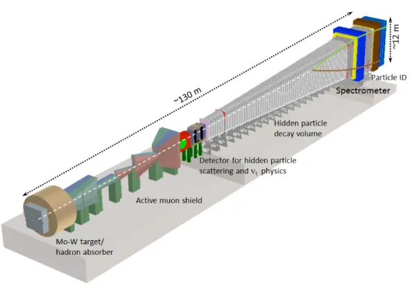
The experimental requirements, as dictated by the phenomenologies of the different Hidden Sector models, are very similar. This allows the design of a general-purpose layout based on a global optimisation of the experimental facility and of the SHiP detector. Figure1shows an overview of the experimental facility from the proton target to the end of the Hidden Sector detector. The main challenges concern the requirement of a highly efficient reduction of the very large beam-induced background, and an efficient and redundant tagging of the residual background down to below 0.1 events in the projected sample of 2·1020 protons on target. Despite the aim to cover long lifetimes, the sensitive volume should be situated as close as possible to the proton target due to the relatively large transverse momentum of the hidden particles resulting from the limited boost of the heavy hadrons (figure2). The minimum distance is only constrained by the need of a system to absorb the electromagnetic radiation and hadrons emerging from the proton target and to reduce the beam-induced muon flux.
2019 JINST 14 P03025
Figure 1. Overview of the target and experimental area for the SHiP detector as implemented in the physics simulation.
of the hadron absorber in the experimental hall and consists of a chain of magnets which extends over a length of∼40 m.
2019 JINST 14 P03025
0 0.1 0.2 0.3 0.4 0.5
Polar production angle [rad] 1 10 2 10 3 10 Entries SHiP acceptance
Dark photon from p-bremsstrahlung Dark photon from meson decays Heavy Neutral Lepton
0 0.1 0.2 0.3 0.4 0.5
Decay opening angle [rad] 1 10 2 10 3 10 Entries
Dark photon from p-bremsstrahlung Dark photon from meson decays Heavy Neutral Lepton
Figure 2. (Left) Polar production angle with a beam momentum of 400 GeV/cfor dark photons (A) produced in proton bremsstrahlung (mA=2.0 GeV/c2) and in meson decays (mA=0.9 GeV/c2), and for heavy neutral
leptons (HNL) (mHNL=1.0 GeV/c2) from decays of charm hadrons. The arrow indicates the acceptance of
the SHIP fiducial volume, given by the transverse size of the decay volume (Right) Decay opening angles for two-body decays of the same three cases. The geometry of the decay volume has been optimized given the aperture of the spectrometer and the hidden particle kinematics.
discriminate between, a very wide range of models. A dedicated timing detector with∼ 100 ps resolution provides a measure of coincidence in order to reject combinatorial backgrounds. The decay volume is surrounded by background taggers to identify neutrino and muon inelastic scattering in the vacuum vessel walls which may produce long-lived neutral SM particles, such asKL etc. The muon shield and the SHiP detector systems are housed in a∼120 m long underground experimental hall at a depth of∼15 m. To minimise the background induced by the flux of muons and neutrinos interacting with material in the vicinity of the detector, no infrastructure systems are located on the sides of the detector, and the hall is 20 m wide along the entire length.
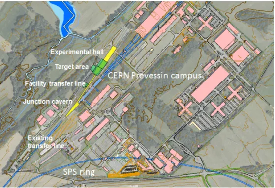
Figure 3shows an overview of the civil engineering required for the experimental facility for SHiP. All civil engineering works are fully located within existing CERN land on the Prevessin campus. This location is very well suited to house the experimental facility, owing to the stable and well understood ground conditions, accessible services and very limited interference with existing buildings, galleries and road structures. By maintaining the entire beam line horizontal and at the same level as the existing splitter region at the end of the SPS extraction line, the experimental hall is conveniently situated at a depth of about 15 m, which is compatible with the requirements from radiation protection while still allowing easy direct access from above without a shaft.
3 Proton beam
2019 JINST 14 P03025
Figure 3. Overview of the required civil engineering for the proposed experimental facility for SHiP on the CERN Prevessin campus. The beam-axis is at a depth of about 10 m which allows trenching the entire complex from the surface. New or reworked construction in yellow (underground) and green (surface); existing tunnels in blue.
2019 JINST 14 P03025
schematically the proposed location of the experimental facility at the CERN North Area site. Thefacility shares about 600 m of the existing TT20 transfer line with the other North Area facilities. At the SPS, the most favourable experimental conditions for SHiP are obtained with a proton beam momentum of around 400 GeV/c. Based on the SPS in its current state and in view of its past performance, a nominal beam intensity of 4·1013protons on target per spill is assumed for the design of the experimental facility and the detector.
In order to reduce the probability of combinatorial background events from residual muons entering the detector decay volume and to respect the limits on the instantaneous beam power deposited in the proton target, SHiP takes advantage of the SPS slow extraction used to provide beam to the CERN North Area through the Long Straight Section 2 of the SPS. The minimum SPS cycle length which is compatible with these requirements is 7.2 s. A beam cycle with a slow extraction of around one second has already been demonstrated in the studies for the experimental facility for SHiP (figure5).
Figure 5. First slow beam extraction tests from the SPS for SHiP with the specific length of about 1 s. The
tests were performed at low intensity of about 1012protons/s. The yellow line represents the proton beam
intensity in the SPS and the white line represents the SPS beam energy.
3.1 Achievable protons on target and beam sharing
2019 JINST 14 P03025
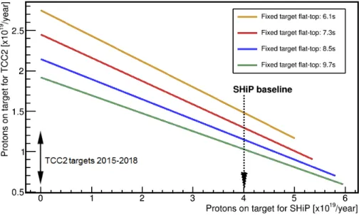
calculated based on acquiring a total of 2·1020protons on target which may thus be achieved infive years of nominal operation.
Figure 6. The expected number of protons on the current North Area targets (TCC2) as a function of the number of protons on target for the SHiP experimental facility with a 1.2 s spill length. The plot shows the performance for different spill durations for the current fixed target facilities between 6.1–9.7 s. The range of the numbers of protons per year delivered to the North Area targets in the years 2015–2018 is indicated. The preferred working point for SHIP is indicated by “SHiP baseline”.
3.2 Extraction beam loss and activation
The slow extraction from the SPS exploits a third-order resonance to achieve a controlled continuous amplitude growth of the transverse oscillations of the circulating protons. The amplitudes grow over several tens of thousands of turns until a slice of the beam crosses the wires of the electrostatic septa, and is guided into the TT20 beam line aperture continuously, as shown in figure7, until the circulating beam in the SPS is completely extracted. The field wires have finite width and inevitably intercept a fraction of the beam, leading to beam losses of the order of 2% of the total intensity. This is an important difference with respect to CNGS operation, which used essentially loss-free fast extraction.
In addition to the increased risk of sparking and damage to the wires due to heating and vacuum pressure rise, the main consequences of beam loss are radio-activation of the extraction region, accumulated radiation damage to sensitive equipment and cables, and the increased cool-down times in case of interventions for repair or maintenance. Activation and personnel dose is already a serious issue in the SPS, and currently reach operational limits with around 1.2·1019 protons slowly extracted per year.
2019 JINST 14 P03025
Figure 7. Envelope of the circulating and the extracted beam along the SPS extraction region, showing the machine aperture and the wires of the electrostatic septum. The passive diffuser or bent crystal are located just upstream of the electrostatic septum to reduce the density of protons impacting the wire.
sending beam to the North Area has also been considered, e.g. over 2·1019protons were slowly extracted to the North Area during 2007. The studies show that a factor of four decrease in the potential radiation dose to personnel is required to achieve the SHiP baseline intensity of 4·1019 protons on target per year. This improvement will need to come from a combination of reduced beam loss, reduced activation per lost proton, and improved or remote interventions.
Extraction losses have been improved already by increasing the stability of the extraction with the help of a feed-forward system on the main quadrupole current to compensate for the ripple induced by the main electricity grid. Also, the septum wires are regularly realigned with the help of improved instrumentation and algorithms. However, a significant decrease (i.e. a factor two or more) can only be expected with substantial changes to the extraction dynamics. Studies involving two techniques based on coherent and incoherent scattering of the protons upstream of the septum (figure7), that would otherwise hit the septum wires, are currently being tested, along with ways of modifying the transverse phase space distribution to reduce particle density at the wires.
The first technique is based on a passive beam scattering device. It consists of a short, thin blade of a high-Z material located upstream of the electrostatic septum wires. The blade intercepts a thin slice of the beam in order to generate an angular spread which reduces the transverse beam density at the wires, resulting in an overall reduction of the beam losses. Simulations show that this technique could bring up to a factor two improvement (figure8). The device is also straightforward to deploy and operate. A prototype diffuser to benchmark the simulations with experiment is being designed and built. It will be installed in the SPS Long Straight Section 2 (LSS2 in figure4) and tested with beam in 2018.
2019 JINST 14 P03025
coasting beam has already demonstrated [13] that beam can be extracted into the TT20 transfer lineusing a bent crystal.
Both the crystal-assisted slow extraction and the diffuser rely on stable conditions and an accurate alignment of the septum wires and the scattering device. A movement of the extraction separatrix in position and more importantly angle is, however, inherent to the SPS extraction mechanism optimised for low beam loss. Use of a dynamic extraction bump could compensate in real-time for these changes in the closed orbit. This could also permit a faster realignment of the beam with the septa, instead of the time-consuming mechanical realignment of the septa.
Figure 8. Relative loss of protons in arbitrary units as a function of the transverse position from simulation
of a 3 mm long, 0.24 mm wide tungsten-rhenium diffuser. The sum of the loss on the diffuser and the
electro-static septum (ES) wires is lower than the total loss with ES wires alone, because the scattering from the diffuser reduces the particle density at the ES sufficiently to result in an overall loss reduction. A factor two improvement is obtained for the optimal position.
A final set of studies focuses on manipulation of the transverse phase-space distribution, using either higher-order multipole magnets or a pair of septum elements in which the configuration of the conductor and magnetic material is used to separate the high-field region from the zero-field region without intervening physical material (“massless septa”), to reduce the particle density at the septum wires without increasing losses elsewhere in the extraction system. These approaches are being studied in simulation and proof-of-principle measurements have been planned for 2018. First studies of combining these techniques with the diffuser, or the crystal, indicate that it can potentially improve the loss reduction well beyond a factor two.
The different mitigation techniques are also complemented by studies of alternative materials for construction of septum sub-systems like titanium or carbon nanotubes to reduce activation, and developments of machine assisted intervention techniques.
3.3 Spill harmonic content
2019 JINST 14 P03025
the help of a timing detector. The requirement on time resolution is derived from the likelihood ofcoincidental muons. The likelihood is directly related to the proton interaction rate in the target, which should have minimal variations. The baseline beam parameters and the average residual muon flux in the detector acceptance requires a timing detector with a time resolution ofO(100)ps. Rejection of combinatorial background is thus one of the main drivers for a highly uniform extraction of the spill.
In 2017 sample spills were generated with the SHiP beam cycle, with the encouraging result that the spill harmonic content is not worse than for the longer spills used for the North Area. Contributions are dominated at low frequency by the effect of harmonics on the main electricity grid affecting the extraction beam dynamics. To this end, improvements of the stability of the slow extraction are also aiming at improving the uniformity of the spill structure. At higher frequencies the residual radio frequency structure of the beam dominates.
3.4 Beam line to proton target
The location of the SHiP proton target in the North Area allows the re-use of about 600 m of the present TT20 transfer line, which has sufficient aperture for the slow-extracted beam at 400 GeV/c. The new dedicated beam transfer line to the experimental facility for SHiP branches off at the end of the TT20 transfer line with the help of a set of newly proposed bi-polar splitter magnets which replaces the existing ones. The new magnets allow both maintaining the present function of splitting the beam between the proton target for the experimental area currently hosting the COMPASS experiment [14] and the rest of the existing North Area facilities, and to alternatively switch the entire spill to the dedicated transfer line for SHiP, on a cycle-by-cycle basis. The present magnet is an in-vacuum Lambertson septum with a yoke machined from solid iron, with the coil based on a water-cooled lead of copper with an insulation of compacted MgO powder [15]. For the new magnets a laminated yoke is required in order to rapidly perform the polarity switch between SPS cycles, which implies ramping the field reliably in about 2 s. The new magnets, shown in figure9, must also have a larger horizontal aperture, as the beam is deflected to different sides of the magnet axis for SHiP and for North Area operation. R&D and prototyping of the laminated yoke is underway to study the very tight mechanical tolerances required in the septum region in order to maintain low beam losses. Similar MgO coil technology as used in the existing splitter will provide the required radiation resistance.
2019 JINST 14 P03025
Figure 9. Cross-section of the new “MSSB-S” splitter magnet. The cycle-to-cycle polarity switching
requires a laminated iron yoke. The 7.5 mm beam gap is made significantly wider than in the original splitter
and extends to both sides of the septum to accommodate both the deflection of the SHiP beam to one side and alternatively splitting the beam between the other North Area facilities on the other side. All dimensions are in mm.
Figure 10. Optics shown by the beta function in the horizontal (black solid line) and vertical plane (red
dashed line) along the entire length of the beam line from the SPS extraction (s=0 m) in LSS2 to the SHiP
proton target located at arounds =900 m. The new section of beam line is matched to the existing TT20
2019 JINST 14 P03025
through the dipole aperture with very low losses. The quadrupoles in TT20 are already laminatedand suited to cycle-to-cycle switching.
For the new beam line, around six new corrector dipoles are assumed. In addition, five standard SPS quadrupole magnets will be required to control the vertical beam size through the dipole apertures, and provide flexibility and tunability of the beam spot size and dispersion at the proton target. In order to produce sufficient dilution of the beam power in the SHiP proton target, the slow extraction is combined with a beam spot of at least 6 mm root-mean square in both planes and a large sweep of the beam over the target surface. The beam sweep is implemented with two orthogonal kicker magnets located after the last bending dipole magnet at 120 m upstream of the target, with Lissajous powering functions to produce a circular sweep. With a free drift length for the beam of about 120 m and a bending angle of 0.25 mrad per plane, it is possible to achieve a sweep radius of 30 mm. Since the survival of the proton target relies critically on the beam dilution, the SPS beam is interlocked with the beam dilution system and the instantaneous loss rate at the target. The overall layout and clearances allow civil engineering to take place along the entire experi-mental facility starting from the middle of the new transfer line and up to the end of the experiexperi-mental hall during beam operation for the other North Area facilities.
4 Proton target and target complex
4.1 Design constraints for the proton target
The physics scope of the SHiP experiment requires a proton target which maximises the production ofD andB mesons, and photons. At the same time, the proton interactions give rise to copious direct production of short-lived meson resonances, as well as pions and kaons. While a hadron absorber of a few meters of iron is sufficient to absorb the hadrons and the electromagnetic radiation emerging from the target, the decays of the pions, kaons and short-lived meson resonances result in a large flux of muons and neutrinos. In order to reduce the flux of neutrinos, in particular the flux of muon neutrinos and the associated muons, the pions and kaons should be stopped as efficiently as possible before they decay. The target should thus be made of a material with the highest possible atomic mass and atomic charge. It should be sufficiently long to intercept virtually all of the proton intensity and to contain the majority of the hadronic shower with minimum leakage. Simulation [16] shows that re-interactions of primary protons and interactions of secondaries produced in the nuclear cascades also contribute with a significant amplification of the signal yields. For instance, in the case of charm production, the cascade processes contribute by more than doubling the yield as compared to what is expected from only the primary proton-nucleus interactions.
2019 JINST 14 P03025
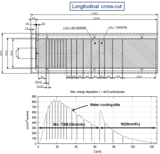
target in order to reduce the energy density and create acceptable stresses in the blocks. The blocksare all interleaved with 5 mm wide slots for water cooling. Tantalum alloy cladding of the TZM and the tungsten blocks is considered in order to prevent corrosion and erosion by the high flow rate of the water cooling. In order to respect the material limits derived from thermo-mechanical stresses, the thickness of each block together with the location of each cooling slot has been optimised to provide a relatively uniform energy deposition and sufficient energy extraction. Using FLUKA Monte Carlo simulations [17] and ANSYS finite element analyses, the preliminary target design has been shown to limit the peak power density in the target blocks to below 850 J/cm3/spill and compressive stresses below 300 MPa in the core of the shower for a 6 mm RMS spot size and 30 mm single-turn sweep radius. Figure11(top) shows the preliminary proton target as designed for the SHiP Technical Proposal [1]. The total dimensions of the target are 1.2 m in length with transverse dimensions of 30 × 30 cm2. Figure11 (bottom) shows the maximum energy density per spill of 4·1013protons on target.
Figure 11. (Top) Preliminary design of the proton target configuration. All dimensions are in mm. The right-slanted hatched region in the top drawing shows the TZM blocks and the left-slanted hatched region the tungsten blocks. (Bottom) Peak energy deposition in the proton target during a spill of 4·1013protons.
2019 JINST 14 P03025
the radiation damage in terms of the displacement per atom, as well as the internal production ofhydrogen and helium gas, indicate that the current target design ensures the longevity of the target, but the limited availability of data in literature call for accelerated aging studies of the materials with irradiation. A replica target is being designed and built for testing with beam in 2018.
The proton target blocks are assembled in a double-walled vessel. The inner vessel enforces the high-flow water circulation between the proton target blocks and ensures a pressurised water cooling of 15–20 bar in order to avoid water boiling in contact with the target blocks. A flow rate of ∼180 m3/h is envisaged. The outer vessel acts as a safety hull to contain hypothetical leaks, and is filled with an inert gas to prevent corrosion.
Figure 12. Overview of the main components of the target complex. The proton beam line arrives from the left of the target bunker. The target is located in the centre of the target bunker and the first section of the muon shield in terms of the magnetised hadron absorber is integrated in the downstream end of the bunker.
4.2 Preliminary design of the target complex
2019 JINST 14 P03025
limited passage of about 20 cm in diameter for the beam vacuum chamber. The 5 m thick downstreamshielding acts as a hadron absorber with the double objective of absorbing the secondary hadrons and the residual non-interacting protons emerging from the target, and significantly reducing the exposure of the downstream active muon shield to radiation. The overall shielding is designed to respect the limits from radiological and environmental protection applicable at CERN.
A helium-vessel containing high-purity helium gas (> 99%) at atmospheric pressure encloses the SHiP proton target and the entire iron shielding. This is required to protect the equipment from radiation-accelerated corrosion as well as to avoid the production of high-mass radioactive isotopes from secondary neutrons interacting with air.
5 Suppression of beam-induced background
5.1 Active muon shield
The total flux of muons emerging from the proton target with a momentum larger than 1 GeV/c
amounts toO(1011) muons per spill of 4·1013protons. In order to control the background from random combinations of muons producing fake decay vertices in the detector decay volume and from muon deep inelastic scattering producing long-lived neutral particles in the surrounding material, and to respect the occupancy limits of the sub-detectors, the muon flux in the detector acceptance must be reduced by several orders of magnitude over the shortest possible distance. To this end, a muon shield entirely based on magnetic deflection has been developed [18,19] (figure1).
Figure 13shows schematically the field configuration of the muon shield magnets. The first section of the muon shield starts within the hadron absorber with the integration of a coil which magnetises the iron shielding block, and continues with a set of freestanding magnets over a length of ∼ 20 m. The purpose of the first section is to deflect the positively and negatively charged muons on either side of the beam axis. As shown by the trajectories of the muons in figure13, lower momentum muons and muons with larger transverse momenta are swept out of the core field before the end of the first section. Due to the return fields, a large fraction of these muons are bent back towards the detector acceptance. For this reason, the second section serves two purposes. In addition to providing further bending power to deflect out of acceptance the higher momentum muons, it should also give the lower momentum muons another magnetic kick outwards. This 20 m section therefore consists of a series of magnets with the return field close to the z-axis. The residual muons entering the decay volume after the muon shield are mainly due to stochastic processes involving large energy losses and large angle scattering in the muon shield material.
In order to achieve a high magnetic flux of 1.7–1.8 T in the core at low current and with coils of small cross-sections, grain-oriented steel is considered as the yoke material for the freestanding magnets [18]. The actual field configuration for the entire muon shield has been optimised with the help of machine learning techniques using a large sample of muons from a full GEANT4 [20] simulation of 2·1010 protons on the SHiP proton target. Engineering studies are underway to study the optimal assembly techniques. The total mass of the muon shield magnets is of the order of 1500 tonnes. The current design allows reducing the rate of residual muons above 1 GeV/c
2019 JINST 14 P03025
Figure 13. Horizontal cross-section of the muon shield magnet configuration at the level of the beam-axis. The direction up/down of the vertical magnetic field is illustrated by the blue/green colour of the iron poles of the magnets. Typical trajectories of muons across the momentum spectrum are overlaid. Reproduced
from [19]. CC BY 3.0.
5.2 Vacuum vessel
2019 JINST 14 P03025
Figure 14. Vertex distribution of signal candidates produced by neutrino interactions from 2·1020protons
on target assuming air at atmospheric pressure in the fiducial volume with a soft selection for heavy neutral
leptons (left), as compared to the situation with a vacuum vessel evacuated down to a pressure of 10−3bar
(right).
proton target. In addition, residual neutrino interactions as well as muon deep inelastic interactions with the vessel structure are further suppressed by instrumenting the entire decay volume walls with a background tagger system and detecting the additional activity associated with the interactions. Simulation studies show that no background events remain after applying these criteria [1].
The SHiP decay vessel consists of the∼50 m decay volume constructed in S355JO(J2/K2)W Corten steel with upstream outer dimensions of 2.4×4.5 m2and downstream outer dimensions of 5×10 m2. The design of the vessel wall is based on an optimisation aiming at producing a structure as light as possible and as slim as possible in order to stay within the boundaries of the deflected muon flux whilst maintaining the required acceptance. At the same time, the optimisation also accounts for the structural safety norms allowing access to the underground hall while under vacuum and the earthquake loads in the region. Figure15shows the structure of the decay volume. The preliminary design consists of a 30 mm thick continuous inner steel sheet acting as vacuum liner, supported azimuthally by welded T-shaped beams with a steel thickness of 15 mm and a height varying from 300 mm to 450 mm. The structure is further reinforced by longitudinal stiffening profiles between the azimuthal beams.
2019 JINST 14 P03025
Figure 15. Cross-sectional view of the vacuum vessel which provides a pressure ofO(10−3)bar in the decay
volume. The design has been optimised in order for the wall to be as light and as slim as possible, and to incorporate a detector system which tags background events.
6 Conclusions
The SHiP experimental facility will provide a unique experimental platform for physics at the intensity frontier which is complementary to both the searches for new physics at the energy frontier and the direct searches for cosmic Dark Matter. CERN’s accelerator complex makes for an ideal siting for the experimental facility. The assumed availability of 2·1020protons on target at 400 GeV/c
in about five years of nominal operation and an environment of extremely low background compares favourably with the potential of other existing facilities.
The two-fold SHiP apparatus is sensitive both to decays and to scattering signatures, and is able to probe a wide variety of models with light long-lived exotic particles in a largely unexplored domain of very weak couplings and masses up toO(10)GeV/c2. This puts it in a unique position worldwide to resolve several of the major observational puzzles of particle physics and cosmology. In addition, the same facility enables the study of interactions of tau neutrino and anti-tau neutrinos, as well as neutrino-induced charm production by all neutrino species. A more recent investigation also shows that an additional detector on the SHiP beam line with a proton target consisting of thin wires and operating in parallel would allow a search for lepton flavour violating tau lepton decays at a sensitivity that could be highly competitive with projections of approved experiments.
2019 JINST 14 P03025
AcknowledgmentsThe SHiP Collaboration wishes to thank the Castaldo company (Naples, Italy) for their contribu-tion to the development studies of the decay vessel. The support from the Nacontribu-tional Research Foundation of Korea with grant numbers of 2018R1A2B2007757, 2018R1D1A3B07050649, 2018R1D1A1B07050701, 2017R1D1A1B03036042, 2017R1A6A3A01075752, 2016R1A2B40-12302, and 2016R1A6A3A11930680 is acknowledged. The support from the Russian Foundation for Basic Research, grant 17-02-00607, and the support from the TAEK of Turkey are acknowledged.
References
[1] SHiP collaboration,A facility to Search for Hidden Particles (SHiP) at the CERN SPS,
arXiv:1504.04956.
[2] S. Alekhin et al.,A facility to Search for Hidden Particles at the CERN SPS: the SHiP physics case,
Rept. Prog. Phys.79(2016) 124201[arXiv:1504.04855].
[3] SHiP collaboration,Addendum to Technical Proposal: A Facility to Search for Hidden Particles
(SHiP) at the CERN SPS,CERN-SPSC-2015-040(2015).
[4] G.F. Giudice and R. Rattazzi,Theories with gauge mediated supersymmetry breaking,Phys. Rept.322
(1999) 419[hep-ph/9801271].
[5] I. Yu. Kobzarev, L.B. Okun and I. Ya. Pomeranchuk,On the possibility of experimental observation of
mirror particles,Sov. J. Nucl. Phys.3(1966) 837.
[6] R. Foot, H. Lew and R.R. Volkas,A Model with fundamental improper space-time symmetries,
Phys. Lett.B 272(1991) 67.
[7] R. Foot and X.-G. He,Comment on Z Z-prime mixing in extended gauge theories,Phys. Lett.B 267
(1991) 509.
[8] B. Patt and F. Wilczek,Higgs-field portal into hidden sectors,hep-ph/0605188.
[9] R. Essig et al.,Working Group Report: New Light Weakly Coupled Particles, inProceedings of the
2013 Community Summer Study on the Future of U.S. Particle Physics, Snowmass on the Mississippi,
Minneapolis, MN, U.S.A., 29 July–6 August, 2013,arXiv:1311.0029,
http://www.slac.stanford.edu/econf/C1307292/docs/IntensityFrontier/NewLight-17.pdf.
[10] J. Alexander et al.,Dark Sectors 2016 Workshop: Community Report,arXiv:1608.08632,
FERMILAB-CONF-16-421 (2016).
[11] OPERA collaboration,The OPERA experiment in the CERN to Gran Sasso neutrino beam,
2009JINST4P04018.
[12] E. Gschwendtner et al.,CNGS, CERN Neutrinos to Gran Sasso, five years of running a 500 kilowatt
neutrino beam facility at CERN, inProceedings of IPAC2013, Shanghai, China, 12–17 May 2013,
pp. 211–213.
[13] K. Elsener, G. Fidecaro, M. Gyr, W. Herr, J. Klem, U. Mikkelsen et al.,Proton extraction from the
CERN SPS using bent silicon crystals,Nucl. Instrum. Meth.B 119(1996) 215.
[14] COMPASS collaboration,http://wwwcompass.cern.ch/.
[15] L.R. Evans et al.,The steel septum magnets for beam splitting at the CERN SPS, inProceedings of the
6thInternational Conference on Magnet Technology (MT-6), Bratislava, Slovakia, 29 August–2
2019 JINST 14 P03025
[16] H. Dijkstra and T. Ruf,Heavy Flavour Cascade Production in a Beam Dump,
CERN-SHiP-NOTE-2015-009(2015).
[17] A. Ferrari, P.R. Sala, A. Fasso and J. Ranft,FLUKA: A multi-particle transport code (Program
version 2005),CERN-2005-010, SLAC-R-773, INFN-TC-05-11 (2005).
[18] V. Bayliss, M. Courthold and T. Rawlings,Active Muon Shield - Preliminary Design Report,
CERN-SHiP-NOTE-2015-003(2015).
[19] SHiP collaboration,The active muon shield in the SHiP experiment,2017JINST12P05011
[arXiv:1703.03612].
[20] GEANT4 collaboration,GEANT4: A Simulation toolkit,Nucl. Instrum. Meth.A 506(2003) 250.
[21] G. Anelli et al.,Proposal to measure the rare decayK+→π+νν¯at the CERN SPS,