Introduction to Networking
Credits
Illustrations: Mauro Toselli Editorial Support: Sue Blumenberg Cover Design: Aimee Andrion
The SketchNote illustrations were drawn on an iPad using Paper by www.fiftythree.com using a dedicated stylus pencil. The illus-trations were converted from PNG to SVG and EPS vector formats using www.vectormagic.com. The technical figures for the book were drawn with OmniGraffle.
Printing History
2015-May-25 Original Printing - CreateSpace
Copyright Details
This book is Copyright Charles R. Severance.
The paper/print version of this book is licensed under a Creative Commons Attribution-NonCommercial 4.0 International License. Permission is specifically granted to make copies as necessary of all or part of the materials in this book as part of a course or course packet.
http://creativecommons.org/licenses/by-nc/4.0
Electronic copies of this book in EPUB, PDF, and HTML are licensed under a Creative Commons Attribution 4.0 International License.
http://creativecommons.org/licenses/by/4.0/
Preface
The goal of this book is to provide a basic understanding of the technical design and architecture of the Internet. The book is aimed at all audiences – even those with absolutely no prior tech-nical experience or math skills. The Internet is an amazingly beau-tiful design and should be understood by all who use it.
While this book is not about the Network+ or CCNA certifications, I hope it serves as a way to give students interested in these certifications a good starting point.
I want to thank Pamela Fox of Khan Academy for coming up with the idea of an introductory network technology course using open materials.
I initially developed this material as a single week’s lecture in the SI502 - Networked Computing course that I taught at the Univer-sity of Michigan School of Information starting in 2008. I refined and expanded the material to be three weeks of the Internet His-tory, Technology, and Security (IHTS) course that I have taught to over 100,000 students on Coursera starting in 2012. This book adds further detail to create a standalone text that can be read for enjoyment or used to support an introductory course that fo-cuses on the Internet’s architecture.
This book has been particularly fun in that it is a collaboration with my friends Mauro Toselli (@xlontrax) and Sue Blumenberg. I met Mauro and Sue in 2012 when they became volunteer Community Teaching Assistants (CTAs) for my IHTS course on Coursera. Over the past three years we have become friends and colleagues. It is a great example of how open education can bring people to-gether.
There is supporting material for this book at
http://www.net-intro.com/
If you like the book, let us know. Send us a tweet with your
thoughts. You can also send a tweet if you find an error in the book.
Charles R. Severance (@drchuck) www.dr-chuck.com
Contents
1 Introduction 1
1.1 Communicating at a Distance . . . 1
1.2 Computers Communicate Differently . . . 4
1.3 Early Wide Area Store-and-Forward Networks . . . 5
1.4 Packets and Routers . . . 6
1.5 Addressing and Packets . . . 7
1.6 Putting It All Together . . . 8
1.7 Glossary . . . 9
1.8 Questions . . . 10
2 Network Architecture 13 2.1 The Link Layer . . . 14
2.2 The Internetwork Layer (IP) . . . 16
2.3 The Transport Layer (TCP) . . . 18
2.4 The Application Layer . . . 20
2.5 Stacking the Layers . . . 21
2.6 Glossary . . . 21
2.7 Questions . . . 22
3 Link Layer 25 3.1 Sharing the Air . . . 26
3.2 Courtesy and Coordination . . . 28
3.3 Coordination in Other Link Layers . . . 29
3.4 Summary . . . 30
vi CONTENTS
3.5 Glossary . . . 31
3.6 Questions . . . 31
4 Internetworking Layer (IP) 35 4.1 Internet Protocol (IP) Addresses . . . 37
4.2 How Routers Determine the Routes . . . 39
4.3 When Things Get Worse and Better . . . 39
4.4 Determining Your Route . . . 41
4.5 Getting an IP Address . . . 45
4.6 A Different Kind of Address Reuse . . . 47
4.7 Global IP Address Allocation . . . 48
4.8 Summary . . . 49
4.9 Glossary . . . 49
4.10Questions . . . 50
5 The Domain Name System 57 5.1 Allocating Domain Names . . . 58
5.2 Reading Domain Names . . . 59
5.3 Summary . . . 59
5.4 Glossary . . . 60
5.5 Questions . . . 60
6 Transport Layer 63 6.1 Packet Headers . . . 64
6.2 Packet Reassembly and Retransmission . . . 65
6.3 The Transport Layer In Operation . . . 67
6.4 Application Clients and Servers . . . 68
6.5 Server Applications and Ports . . . 68
6.6 Summary . . . 70
6.7 Glossary . . . 70
CONTENTS vii
7 Application Layer 73
7.1 Client and Server Applications . . . 73
7.2 Application Layer Protocols . . . 75
7.3 Exploring the HTTP Protocol . . . 76
7.4 The IMAP Protocol for Retrieving Mail . . . 80
7.5 Flow Control . . . 81
7.6 Writing Networked Applications . . . 83
7.7 Summary . . . 84
7.8 Glossary . . . 84
7.9 Questions . . . 85
8 Secure Transport Layer 89 8.1 Encrypting and Decrypting Data . . . 90
8.2 Two Kinds of Secrets . . . 91
8.3 Secure Sockets Layer (SSL) . . . 92
8.4 Encrypting Web Browser Traffic . . . 93
8.5 Certificates and Certificate Authorities . . . 94
8.6 Summary . . . 95
8.7 Glossary . . . 96
8.8 Questions . . . 97
9 The OSI Model 101 9.1 Physical (Layer 1) . . . .102
9.2 Data Link (Layer 2) . . . .102
9.3 Network (Layer 3) . . . .102
9.4 Transport (Layer 4) . . . .103
9.5 Session (Layer 5) . . . .103
9.6 Presentation (Layer 6) . . . .103
9.7 Application (Layer 7) . . . .103
9.8 Comparing the OSI and TCP/IP Models . . . 104
9.9 Link Layer (TCP/IP) . . . 104
viii CONTENTS
9.11Transport Layer (TCP/IP) . . . 105
9.12Application Layer (TCP/IP) . . . 105
9.13Conclusion . . . 106
9.14Glossary . . . 106
9.15Questions . . . 106
Chapter 1
Introduction
Using the Internet seems pretty easy. We go to a web address and up comes a page. Or we go to our favorite social site and see pictures of our friends, families, and pets. But it takes a lot of complex software and hardware to make the Internet seem so simple. The design of the technologies that make today’s Inter-net work started in the 1960s, and there were over 20 years of research into how to build internetworking technologies before the first “Internet” was built in the late 1980s by academics in a project called NSFNet. Since then, the research and development into improving network technologies has continued as networks have become far larger and faster and globally distributed with billions of computers.
In order to better understand how today’s Internet works, we will take a look at how humans and computers have communicated using technology over the years.
1.1
Communicating at a Distance
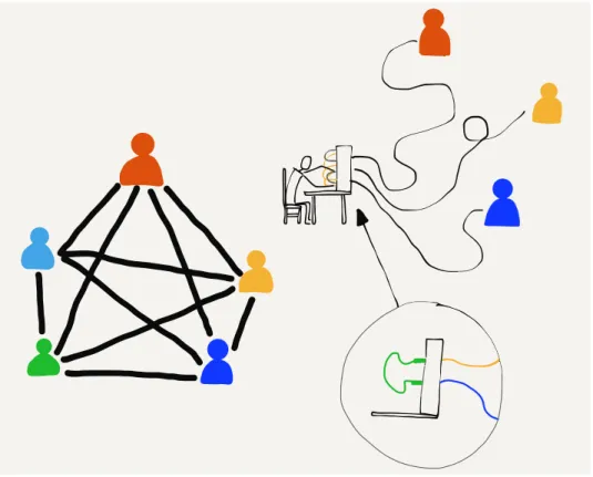
Imagine a group of five people in a room sitting in a circle. As long as they are courteous and don’t have more than one conversation at the same time, it’s quite natural for any person to talk to any other person in the room. They just need to be able to hear each other and coordinate how to use the shared space in the room.
But what if we put these people in different rooms so they can no longer see or hear each other? How could pairs of people communicate with each other then? One way might be to run a wire between each pair of people with a microphone on one end and a speaker on the other end. Now everyone could still hear all
2 CHAPTER 1. INTRODUCTION
the conversations. They would still need to be courteous to make sure that there was only one conversation going on at the same time.
Each person would need four speakers (one for each of the other people) and enough pieces of wire to connect all the microphones and speakers. This is a problem with five people and it gets far worse when there are hundreds or thousands of people.
Using wires, microphones, and speakers is how early telephone systems from the 1900s allowed people to make phone calls. Be-cause they could not have separate wires between every pair of telephones, these systems did not allow all pairs of people to be connected at the same time. Each person had a single connection to a human “operator”. The operator would connect two wires to-gether to allow a pair of people to talk, and then disconnect them when the conversation was finished.
Figure 1.1: Connecting Using Telephone Operators
1.1. COMMUNICATING AT A DISTANCE 3
But what if thousands people who are hundreds of kilometers
apart need to be able to communicate? We can’t run
100-kilometer wires from each home to a single central office. What the telephone companies did instead was to have many central offices and run a few wires between the central offices, then share connections between central offices. For long distances, a connection might run through a number of central offices. Before the advent of fiber optic, long-distance telephone calls were carried between cities on poles with lots of separate wires. The number of wires on the poles represented the number of possible simultaneous long-distance phone calls that could use those wires.
Figure 1.2: Long-Distance Telephone Poles
Since the cost of the wires went up as the length of the wire increased, these longer connections between offices were quite expensive to install and maintain, and they were scarce. So in the early days of telephones, local calls were generally quite inexpen-sive. But long-distance calls were more expensive and they were charged by the minute. This made sense because each minute you talked on a long-distance call, your use of the long-distance wires meant no one else could use them. The telephone compa-nies wanted you to keep your calls short so their long-distance lines would be available for other customers.
4 CHAPTER 1. INTRODUCTION
photo and see lots of wires on a single pole, it generally means they were telephone wires and not used to carry electricity.
1.2
Computers Communicate Differently
When humans talk on the phone, they make a call, talk for a while, and then hang up. Statistically, most of the time, humans are not talking on the phone. At least they weren’t before ev-eryone had smartphones. But computers, including the applica-tions on your smartphone, communicate differently than humans do. Sometimes computers send short messages to check if an-other computer is available. Computers sometimes send medium-sized information like a single picture or a long email message. And sometimes computers send a lot of information like a whole movie or a piece of software to install that might take minutes or even hours to download. So messages between computers can be short, medium, or long.
In the earliest days of connecting computers to one another, pairs of computers were connected with wires. The simplest way to send data from one computer to another was to line up the out-going messages in a queue and send the messages one after another as fast as the computers and the wires could carry the data. Each message would wait for its turn until the messages ahead of it were sent, and then it would get its chance to be sent across the connection.
When the computers were in the same building, the building owner could run wires to connect them. If the computers were in the same town, the owners of the computers generally had to lease wires from the telephone companies to connect their computers. They often would have the phone company connect the wires together in their central office so that it was not necessary for one computer to “dial” the other computer to
send data. These leased lines were convenient for computer
communications because they were “always on”, but they were also quite expensive because they were used 24 hours a day.
1.3. EARLY WIDE AREA STORE-AND-FORWARD NETWORKS 5
exchange data. This worked pretty well as long as you were only using one brand of computers, because each computer company had their own way of using telephone wires to connect their com-puters together and send data.
1.3
Early
Wide
Area
Store-and-Forward
Networks
In the 1970s and 1980s, people working at universities around the world wanted to send each other data and messages using these computer-to-computer connections. Since the cost for each connection was so high and increased with distance, computers generally only had connections to other nearby computers. But if the computer that you were connected to was connected to another computer and that computer in turn was connected to another computer, and so on, you could send a message a long distance as long as each of the computers along the route of the message agreed to store and forward your message.
Figure 1.3: Store-and-Forward Networks
6 CHAPTER 1. INTRODUCTION
Sending entire messages one at a time this way, a message might take minutes, hours, or even days to arrive at its ultimate desti-nation, depending on the traffic at each of the hops. But even if it took a few hours for an email message to find its way from one part of the country to another, this was still much quicker and easier than sending a letter or postcard.
1.4
Packets and Routers
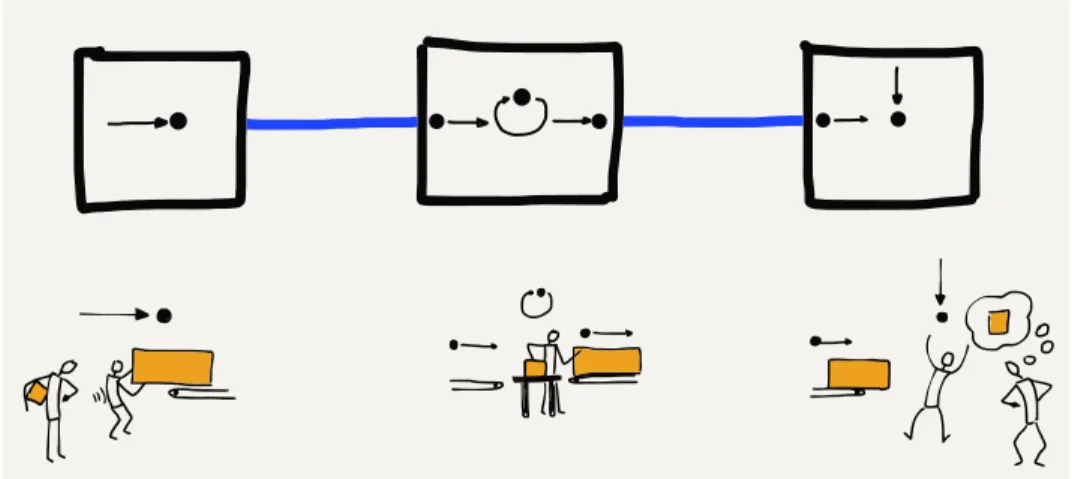
The most important innovation that allowed messages to move more quickly across a multi-hop network was to break each mes-sage into small fragments and send each fragment individually. In networking terms, these pieces of messages are called “pack-ets”. The idea of breaking a message into packets was pioneered in the 1960s, but it was not widely used until the 1980s because it required more computing power and more sophisticated network-ing software.
When messages are broken into packets and each packet is sent separately, if a short message was sent after a large message had begun, the short message did not have to wait until the entire long message was finished. The first packet of the short message only had to wait for the current packet of the large message to be finished. The system alternated sending packets from the long and short messages until after a while the short message was completely sent and the long message resumed making full use of the network connection.
Breaking the message into packets also greatly reduced the amount of storage needed in the intermediate computers be-cause instead of needing to store an entire message for as long as a few hours, the intermediate computer only needed to store a few packets for a few seconds while the packets waited for their turns on the outbound link.
As networks moved away from the store-and-forward approach, they started to include purpose computers that special-ized in moving packets. These were initially called “Interface Mes-sage Processors” or “IMPs” because they acted as the interface between general-purpose computers and the rest of the network. Later these computers dedicated to communications were called “routers” because their purpose was to route the packets they
received towards their ultimate destination.
1.5. ADDRESSING AND PACKETS 7
Figure 1.4: Sending Packets
vendors to the same network. To connect any computer to the network, now all you needed to do was connect it to one router and then the rest of the communication details were handled by the other routers.
When multiple computers at one location were connected to-gether in a “Local Area Network” (or LAN) using physical wiring, you would connect a router to the local area network. By sending data through the router, all the computers on the local area network could send data across the “Wide Area Network” (or WAN).
1.5
Addressing and Packets
8 CHAPTER 1. INTRODUCTION
available.
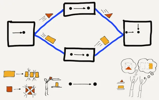
When a long message was split into much smaller packets and each packet was sent individually, the source and destination ad-dresses had to be added to each packet, so that routers could choose the best path to forward each packet of the message. In addition to the source and destination addresses, it was also nec-essary to add data to each packet indicating the “offset” or po-sition of the packet in the overall message so that the receiving computer could put the packets back together in the right order to reconstruct the original message.
1.6
Putting It All Together
So when we combine all this together we can understand the ba-sic operation of today’s Internet. We have specialized computers called “routers” that know how to route packets along a path from a source to a destination. Each packet will pass through multiple routers during its journey from the source computer to the desti-nation computer.
Even though the packets may be part of a larger message, the routers forward each packet separately based on its source and destination addresses. Different packets from the same message may take different routes from the source to the destination. And sometimes packets even arrive out of order; a later packet might arrive before an earlier packet, perhaps because of a data “traffic jam”. Each packet contains an “offset” from the beginning of the message so that the destination computer can reassemble the packets in the correct order to reconstruct the original message.
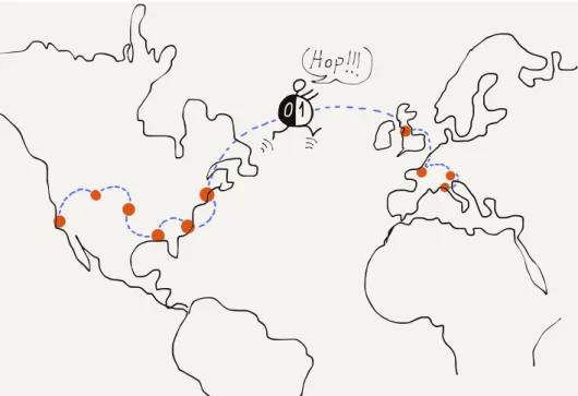
By creating a network using multiple short hops, the overall cost of communicating across a large geographical area could be spread across a large number of connecting groups and individ-uals. Normally, packets would find the shortest path between the source and destination, but if a link on that path was an overloaded or broken, the routers could cooperate and reroute traffic to take slightly longer paths that would get packets from a source to a destination as quickly as possible.
1.7. GLOSSARY 9
Figure 1.5: Connecting Around the World
computer like a smartphone, from several computers in the same building, or from thousands of computers connected to a univer-sity campus network. The term “Internet” comes from the idea of “internetworking”, which captures the idea of connecting many networks together. Our computers connect to local networks and the Internet connects the local networks together so all of our computers can talk to each other.
1.7
Glossary
address: A number that is assigned to a computer so that mes-sages can be routed to the computer.
hop: A single physical network connection. A packet on the In-ternet will typically make several “hops” to get from its source computer to its destination.
LAN: Local Area Network. A network covering an area that is
limited by the ability for an organization to run wires or the power of a radio transmitter.
10 CHAPTER 1. INTRODUCTION
operator (telephone): A person who works for a telephone com-pany and helps people make telephone calls.
packet: A limited-size fragment of a large message. Large mes-sages or files are split into many packets and sent across the Internet. The typical maximum packet size is between 1000 and 3000 characters.
router: A specialized computer that is designed to receive incom-ing packets on many links and quickly forward the packets on the best outbound link to speed the packet to its destination.
store-and-forward network: A network where data is sent from one computer to another with the message being stored for relatively long periods of time in an intermediate computer waiting for an outbound network connection to become available.
WAN: Wide Area Network. A network that covers longer
dis-tances, up to sending data completely around the world. A WAN is generally constructed using communication links owned and managed by a number of different organizations.
1.8
Questions
You can take this quiz online at http://www.net-intro.com/quiz/
1. What did early telephone operators do?
a) Maintained cell phone towers
b) Connected pairs of wires to allow people to talk c) Installed copper wire between cities
d) Sorted packets as they went to the correct destination
2. What is a leased line?
a) A boundary between leased and owned telephone equip-ment
b) A connection between a keyboard and monitor
c) A wire that ran from one phone company office to another d) An “always on” telephone connection
1.8. QUESTIONS 11
a) less than a second
b) no more than four seconds c) less than a minute
d) possibly as long as several hours
4. What is a packet?
a) A technique for wrapping items for shipping b) A small box used for storage
c) A portion of a larger message that is sent across a network d) The amount of data that could be stored on an early punched
card
5. Which of these is most like a router?
a) A mail sorting facility b) A refrigerator
c) A high-speed train
d) An undersea telecommunications cable
6. What was the name given to early network routers?
a) Interfaith Message Processors b) Internet Motion Perceptrons c) Instant Message Programs d) Interface Message Processors
7. In addition to breaking large messages into smaller seg-ments to be sent, what else was needed to properly route each message segment?
a) A source and destination address on each message segment b) An ID and password for each message segment
c) A small battery to maintain the storage for each message segment
d) A small tracking unit like a GPS to find lost messages
8. Why is it virtually free to send messages around the world using the Internet?
a) Because governments pay for all the connections b) Because advertising pays for all the connections c) Because so many people share all the resources
Chapter 2
Network Architecture
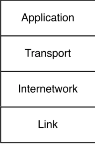
To engineer and build a system as complex as the Internet, en-gineers try to break a single challenging problem into a set of smaller problems that can be solved independently and then put back together to solve the original large problem. The engineers who built the first internets broke the overall problem into four basic subproblems that could be worked on independently by dif-ferent groups.
Transport
Application
Internetwork
Link
Figure 2.1: The Four-Layer TCP/IP Model
They gave these four areas of engineering the following names: (1) Link, (2) Internetwork, (3) Transport, and (4) Application. We visualize these different areas as layers stacked on top of each other, with the Link layer on the bottom and the Application layer on the top. The Link layer deals with the wired or wireless con-nection from your computer to the local area network and the Application layer is what we as end users interact with. A web
14 CHAPTER 2. NETWORK ARCHITECTURE
browser is one example of an application in this Internet architec-ture.
We informally refer to this model as the “TCP/IP model” in refer-ence to the Transport Control Protocol (TCP) used to implement the Transport layer and Internet Protocol (IP) used to implement the Internetwork layer.
We will take a quick look at each of the layers, starting from the “bottom” of the stack.
2.1
The Link Layer
The Link layer is responsible for connecting your computer to its
local network and moving the data across a single hop. The
most common Link layer technology today is wireless network-ing. When you are using a wireless device, the device is only sending data a limited distance. A smartphone communicates with a tower that is a few kilometers away. If you are using your smartphone on a train, it needs to switch to a new tower every few minutes when the train is moving. A laptop that is connected to a WiFi network is usually communicating with a base station within 200 meters. A desktop computer that is connected using a wired connection is usually using a cable that is 100 meters long or shorter. Link layer technologies are often shared amongst multiple computers at the same location.
The Link layer needs to solve two basic problems when dealing with these shared local area networks. The first problem is how to encode and send data across the link. If the link is wireless, engineers must agree on which radio frequencies are to be used to transmit data and how the digital data is to be encoded in the radio signal. For wired connections, they must agree on what voltage to use on the wire and how fast to send the bits across the wire. For Link layer technologies that use fiber optics, they must agree on the frequencies of light to be used and how fast to send the data.
2.1. THE LINK LAYER 15
The idea of breaking a large message into packets and then send-ing each packet separately makes this sharsend-ing easier. If only one computer wants to send data, it will send its packets one right after another and move its data across the network as quickly as it can. But if three computers want to send data at the same time, each computer will send one packet and then wait while the other two computers send packets. After each of the other computers sends a packet, the first computer will send its next packet. This way the computers are sharing access to the network in a fair way.
But how does a computer know if other computers want to send data at the same time? Engineers designed an ingenious method to solve this problem called “Carrier Sense Multiple Access with Collision Detection”, or CSMA/CD. It is a long name for a simple and elegant concept. When your computer wants to send data, it first listens to see if another computer is already sending data on the network (Carrier Sense). If no other computer is sending data, your computer starts sending its data. As your computer is sending data it also listens to see if it can receive its own data. If your computer receives its own data, it knows that the channel is still clear and continues transmitting. But if two computers started sending at about the same time, the data collides, and your computer does not receive its own data. When a collision is detected, both computers stop transmitting, wait a bit, and retry the transmission. The two computers that collided wait different lengths of time to retry their transmissions to reduce the chances of a second collision.
When your computer finishes sending a packet of data, it pauses to give other computers that have been waiting a chance to send data. If another computer senses that your computer has stopped sending data (Carrier Sense) and starts sending its own packet, your computer will detect the other computer’s use of the net-work and wait until that computer’s packet is complete before attempting to send its next packet.
This simple mechanism works well when only one computer wants to send data. It also works well when many computers want to send data at the same time. When only one computer is sending data, that computer can make good use of the shared network by sending packets one after another, and when many computers want to use the shared network at the same time, each computer gets a fair share of the link.
con-16 CHAPTER 2. NETWORK ARCHITECTURE
Figure 2.2: Carrier Sense/Collision Detection
nections and need techniques like CSMA/CD to insure fair access to the many different computers connected to the network. Other link layers like fiber optic cables and leased lines are generally not shared and are used for connections between routers. These non-shared connections are still part of the Link layer.
The engineers working on Link layer technologies focus solving the issues so computers can transmit data across a single link that ranges in distance from a few meters to as long as hundreds of kilometers. But to move data greater distances, we need to send our packets through multiple routers connected by multiple link layers. Each time our packet passes through another link layer from one router to another we call it a “hop”. To send data halfway around the world, it will pass through about 20 routers, or make 20 “hops”.
2.2
The Internetwork Layer (IP)
2.2. THE INTERNETWORK LAYER (IP) 17
and destination address and the router needs to look at the des-tination address to figure out how to best move your packet to-wards its destination. With each router handling packets destined for any of many billions of destination computers, it’s not possible for every router to know the exact location and best route to ev-ery possible destination computer. So the router makes its best guess as to how to get your packet closer to its destination.
Each of the other routers along the way also does its best to get your packet closer to the destination computer. As your packet gets closer to its final destination, the routers have a better idea
of exactly where your packet needs to go. When the packet
reaches the last link in its journey, the link layer knows exactly where to send your packet.
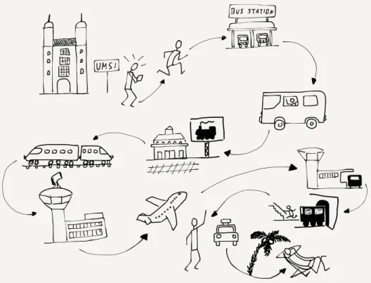
We use a similar approach to route ourselves when going on hol-iday. A holiday trip also has many hops. Perhaps the first hop is driving your car or taking a cab or bus to a train station. Then you take a local train from your small town to a larger city. In the larger city you take a long-distance train to a large city in another country. Then you take another local train to the small village where you will stay for your holiday. When you get off the train, you take a bus, and when you get off the bus, you walk to your hotel.
If you were on the train between the two large cities and you asked the conductor the exact location of your hotel in the small village, the conductor would not know. The conductor only knows how to get you closer to your destination, and while you are on the long-distance train that is all that matters. When you get on the bus at your destination village, you can ask the bus driver which stop is closest to your hotel. And when you get off the bus at the right bus stop, you can probably ask a person on the street where to find the hotel and get an exact answer.
The further you are from your destination, the less you need to know the exact details of how to get there. When you are far away, all you need to know is how to get “closer” to your destina-tion. Routers on the Internet work the same way. Only the routers that are closest to the destination computer know the exact path to that computer. All of the routers in the middle of the journey work to get your message closer to its destination.
But just like when you are traveling, unexpected problems or de-lays can come up that require a change in plans as your packets are sent across the network.
18 CHAPTER 2. NETWORK ARCHITECTURE
Figure 2.3: A Multi-Step Trip
any kind of traffic delay or network outage so that packets can be switched from a route that is no longer working to a different route. The routers that make up the core of the Internet are smart and adapt quickly to both small and large outages or failures of network connections. Sometimes a connection slows down be-cause it is overloaded. Other times a connection is physically bro-ken when a construction crew mistabro-kenly digs up a buried wire and cuts it. Sometimes there is a natural disaster like a hurricane or typhoon that shuts down the routers and links in a large ge-ographical area. The routers quickly detect these outages and reroute around them if possible.
But sometimes things go wrong and packets are lost. Dealing with lost packets is the reason for the next layer in our architecture.
2.3
The Transport Layer (TCP)
2.3. THE TRANSPORT LAYER (TCP) 19
But sometimes these packets get lost or badly delayed. Other times the packets arrive at their destination out of order because a later packet found a quicker path through the network than an earlier packet. Each packet contains the source computer’s ad-dress, the destination computer’s adad-dress, and an offset of where this packet “fits” relative to the beginning of the message. Know-ing the offset of each packet from the beginnKnow-ing of the message and the length of the packet, the destination computer can recon-struct the original message even if the packets were received out of order.
As the destination computer reconstructs the message and deliv-ers it to the receiving application, it periodically sends an acknowl-edgement back to the source computer indicating how much of the message it has received and reconstructed. But if the des-tination computer finds that parts of the reconstructed message are missing, this probably means that these packets were lost or badly delayed. After waiting a bit, the destination computer sends a request to the source computer to resend the data that seems to be missing.
The sending computer must store a copy of the parts of the orig-inal message that have been sent until the destination computer acknowledges successful receipt of the packets. Once the source computer receives the acknowledgment of successful receipt of a portion of the message, it can discard the data that has been acknowledged and send some more data.
The amount of data that the source computer sends before wait-ing for an acknowledgement is called the “window size”. If the window size is too small, the data transmission is slowed because the source computer is always waiting for acknowledgments. If the source computer sends too much data before waiting for an acknowledgment, it can unintentionally cause traffic problems by overloading routers or long-distance communication lines. This problem is solved by keeping the window size small at the begin-ning and timing how long it takes to receive the first acknowledge-ments. If the acknowledgments come back quickly, the source computer slowly increases the window size and if the acknowl-edgements come back slowly, the source computer keeps the window size small so as not to overload the network. Just like at the Link layer, a little courtesy on the Internet goes a long way toward ensuring good use of the shared network infrastructure.
20 CHAPTER 2. NETWORK ARCHITECTURE
will be slowed down to match the limitations of the network con-nections between the source and destination computers.
2.4
The Application Layer
The Link, Internetwork, and Transport layers work together to quickly and reliably move data between two computers across a shared network of networks. With this capability to move data reliably, the next question is what networked applications will be built to make use of these network connections.
When the first widely used Internet came into being in the mid-1980s, the first networked applications allowed users to log in to remote computers, transfer files between computers, send mail between computers, and even do real-time text chats between computers.
In the early 1990s, as the Internet came to more people and com-puters’ abilities to handle images improved, the World Wide Web application was developed by scientists at the CERN high-energy physics facility. The web was focused on reading and editing net-worked hypertext documents with images. Today the web is the most common network application in use around the world. But all the other older Internet applications are still in wide use.
Each application is generally broken into two halves. One half of the application is called the “server”. It runs on the destination computer and waits for incoming networking connections. The other half of the application is called the “client” and runs on the source computer. When you are browsing the web using software like Firefox, Chrome, or Internet Explorer, you are running a “web client” application which is making connections to web servers and displaying the pages and documents stored on those web servers. The Uniform Resource Locators (URLs) that your web browser shows in its address bar are the web servers that your client is contacting to retrieve documents for you to view.
2.5. STACKING THE LAYERS 21
2.5
Stacking the Layers
We usually show the four different layers (Link, Internetwork, Transport, and Application) stacked on top of each other with the Application layer at the top and the Link layer at the bottom. The reason we show them this way is because each layer makes use of the layers above and below it to achieve networked communications.
All four layers run in your computer where you run the client ap-plication (like a browser), and all four layers also run in the des-tination computer where the application server is running. You as the end user interact with the applications that make up the top layer of the stack, and the bottom layer represents the WiFi, cellular, or wired connection between your computer and the rest of the Internet.
The routers that forward your packets from one to another to move your packets towards their destination have no understand-ing of either the Transport or Application layers. Routers oper-ate at the Internetwork and Link layers. The source and destina-tion addresses at the Internetwork layer are all that is needed for routers to move your packets across the series of links (hops) to get them to the destination. The Transport and Application lay-ers only come into play after the Internetwork layer delivlay-ers your packets to the destination computer.
If you wanted to write your own networked application, you would likely only talk to the Transport layer and be completely uncon-cerned about the Internetwork and Link layers. They are essen-tial to the function of the Transport layer, but as you write your program, you do not need to be aware of any of the lower-layer details. The layered network model makes it simpler to write net-worked applications because so many of the complex details of moving data from one computer to another can be ignored.
Up next, we will talk about these four layers in more detail.
2.6
Glossary
client: In a networked application, the client application is the one that requests services or initiates connections.
22 CHAPTER 2. NETWORK ARCHITECTURE
glass or plastic. Fiber optic connections are fast and can cover very long distances.
offset: The relative position of a packet within an overall mes-sage or stream of data.
server: In a networked application, the server application is the one that responds to requests for services or waits for incoming connections.
window size: The amount of data that the sending computer is allowed to send before waiting for an acknowledgement.
2.7
Questions
You can take this quiz online at http://www.net-intro.com/quiz/
1. Why do engineers use a “model” to organize their approach to solving a large and complex problem?
a) Because it allows them to build something small and test it in a wind tunnel
b) Because talking about a model delays the actual start of the hard work
c) Because they can break a problem down into a set of smaller problems that can be solved independently
d) Because it helps in developing marketing materials
2. Which is the top layer of the network model used by TCP/IP networks?
a) Application b) Transport
c) Internetwork d) Link
3. Which of the layers concerns itself with getting a packet of data across a single physical connection?
a) Application b) Transport
2.7. QUESTIONS 23
4. What does CSMA/CD stand for?
a) Carrier Sense Multiple Access with Collision Detection b) Collision Sense Media Access with Continuous Direction c) Correlated Space Media Allocation with Constant Division d) Constant State Multiple Address Channel Divison
5. What is the goal of the Internetwork layer?
a) Insure that no data is lost while enroute
b) Get a packet of data moved across multiple networks from its source to its destination
c) Make sure that only logged-in users can use the Internet d) Insure than WiFi is fairly shared across multiple computers
6. In addition to the data, source, and destination addresses, what else is needed to make sure that a message can be reassembled when it reaches its destination?
a) An offset of where the packet belongs relative to the begin-ning of the message
b) A location to send the data to if the destination computer is down
c) A compressed and uncompressed version of the data in the packet
d) The GPS coordinates of the destination computer
7. What is “window size”?
a) The sum of the length and width of a packet b) The maximum size of a single packet
c) The maximum number of packets that can make up a mes-sage
d) The maximum amount of data a computer can send before receiving an acknowledgement
8. In a typical networked client/server application, where does the client application run?
a) On your laptop, desktop, or mobile computer b) On a wireless access point
24 CHAPTER 2. NETWORK ARCHITECTURE
d) In an undersea fiber optic cable
9. What does URL stand for?
a) Universal Routing Linkage b) Uniform Retransmission Logic
Chapter 3
Link Layer
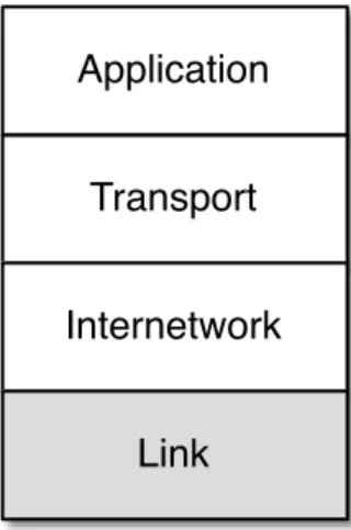
The lowest layer of our Internet Architecture is the Link layer. We call it the “lowest layer” because it is closest to the physical net-work media. Often the Link layer transmits data using a wire, a fiber optic cable, or a radio signal. A key element of the Link layer is that usually data can only be transmitted part of the way from the source computer to the destination computer. Wired Ether-net, WiFi, and the cellular phone network are examples of link layers that can transmit data about a kilometer. Fiber optic ca-bles, particularly those under the oceans, can transmit data up to thousands of kilometers. Satellite links can also send data over long distances.
Transport
Application
Internetwork
Link
Figure 3.1: The Link Layer
Regardless of the distance we can send the data, it is still travel-ing over a stravel-ingle link, and to reach the ultimate destination
26 CHAPTER 3. LINK LAYER
puter requires forwarding packets across multiple links. In this section we will look at how one of the most common link layers functions in some detail. WiFi is a great way to look at many issues that must be solved at the link layer.1
3.1
Sharing the Air
When your laptop or phone is using WiFi to connect to the Internet, it is sending and receiving data with a small, low-powered radio. The radio in your computer can only send data about 300 meters, so your computer sends your packets to the router in your home, which forwards the packets using a link to the rest of the Internet. Sometimes we call the first router that handles your computer’s packets the “base station” or “gateway”.
All computers that are close enough to the base station with their radios turned on receive all of the packets the base station trans-mits, regardless of which computer the packet is supposed to be sent to. They also “hear” all the packets sent by every other nearby computer. So your computer needs a way to know which packets to treat as its own and which packets are being sent to other computers and can be safely ignored.
An interesting side effect of the fact that all the computers within range can hear all packets is that a rogue computer could also be listening to and capturing your packets, perhaps getting ahold of important data like bank account numbers or passwords to online services. We will come back to the issue of protecting your data from prying eyes and ears in a later section.
Every WiFi radio in every device that is ever built is given a unique serial number at the time it is manufactured. This means that each of the computers using WiFi has its own serial number, and the radio in the gateway also has a serial number. You can usually go into a settings screen on your device and look up the serial number for the WiFi radio in your device. It is generally shown in the following form:
0f:2a:b3:1f:b3:1a
This is just a representation of a 48-bit serial number for your WiFi radio. It is also called the “Media Access Control” or “MAC”
1We simplify some of the technical detail in these descriptions to make them
3.1. SHARING THE AIR 27
address. A MAC address is like a “from” or “to” address on a postcard. Every packet (radio postcard) sent across the WiFi has a source and destination address, so all of the computers know which messages are theirs.
When you turn on your computer and connect to a WiFi network, your computer needs to figure out which of the MAC addresses on the WiFi can be used to send packets to the router. When you move from one physical location to another, your computer will be talking to different gateways and each of those gateways will have a different serial number. So when you first connect to a new WiFi, your computer must discover the MAC address for the gateway of that particular WiFi.
To do this, your computer sends a special message to a broadcast address, effectively asking the question, “Who is in charge of this WiFi?” Since your computer knows it is not the gateway itself, it sends a broadcast message with its own serial number as the “from” address and the broadcast address as the “to” address to
ask if there are any gateways present on the WiFi network.
From: 0f:2a:b3:1f:b3:1a To: ff:ff:ff:ff:ff:ff
Data: Who is the MAC-Gateway for this network?
If there is a gateway on the network, the gateway sends a mes-sage containing its serial number back to your computer.
From: 98:2f:4e:78:c1:b4 To: 0f:2a:b3:1f:b3:1a Data: I am the gateway
Welcome to my network
If there are no replies, your computer waits a few seconds and then assumes there is no gateway for this network. When there is no gateway, your computer might show a different WiFi icon or not show the WiFi icon at all. Sometimes there can be more than one gateway, but we will ignore that for a while because it is a little complex and not very common.
28 CHAPTER 3. LINK LAYER
the destination. You want to use the broadcast address as little as possible because every computer connected to the WiFi receives and processes any messages sent to the broadcast address to make sure the messages were not intended for them.
3.2
Courtesy and Coordination
Because many computers are sharing the same radio frequencies, it’s important to coordinate how they send data. When there’s a crowd of people in a room, they can’t all talk at the same time or everything will be garbled. The same thing happens when multi-ple WiFi radios transmit at the same time on the same frequency. So we need some way to coordinate all the radios to make best use of the shared frequencies. We will look at the basics of tech-nical approaches to avoiding lost data due to transmission “colli-sions”.
The first technique is called “Carrier Sense”. The technique is to first listen for a transmission, and if there is already a trans-mission in progress, wait until the transtrans-mission finishes. It might seem like you could wait for a long time, but since all messages are broken into packets, usually your computer only has to wait for the computer currently sending data to finish a packet, after which your computer gets its chance to send data.
If your computer’s WiFi radio listens for data and hears silence, it can begin transmitting. But what if another computer’s WiFi radio that wants to send a packet listened to and heard the same si-lence and decided to start transmitting at exactly the same time? If two or more WiFi radios start transmitting at the same time, all of the data is corrupted and both packets are lost. So once your WiFi radio starts sending a packet it is important for it to listen to make sure it can receive its own data. If it is not receiving the same thing that it is sending, your WiFi radio assumes that a col-lision has happened (this is called Colcol-lision Detection) and stops transmitting, since it knows that no data will be received by the destination WiFi radio.
3.3. COORDINATION IN OTHER LINK LAYERS 29
you” repeatedly to attempt to figure out how to get the conversa-tion restarted. It can be quite comical at times.
The WiFi radios in two computers that send colliding packets are able to solve this problem much better than people can solve the problem. When the WiFi radios detect a collision or garbled transmission, they compute a random amount of time to wait before retrying the transmission. The rules for computing the random wait are set up to make sure the two colliding stations pick different amounts of time to wait before attempting to re-transmit the packet.
The formal name for the listen, transmit, listen, and wait and retry if necessary is called “Carrier Sense Multiple Access with Collision Detection” or CSMA/CD.
It might sound a little chaotic to just “give it a try” and then “give it another try” if your transmission collides with another station’s transmission. But in practice it works well. There is a whole cat-egory of link layers that use this basic pattern of listen, transmit, listen, and optionally retry. Wired Ethernet, cellular telephone data, and even Short Message Service (SMS/Texting) all use this “try then retry” approach.
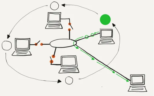
3.3
Coordination in Other Link Layers
Sometimes when a link layer has many transmitting stations and needs to operate at near 100% efficiency for long periods of time, the design takes a different approach. In this approach, there is a “token” that indicates when each station is given the opportunity to transmit data. Stations cannot start a transmission unless they have the token. Instead of listening for “silence” and jumping in, they must wait for their turn to come around.
When a station receives the token and has a packet to send, it sends the packet. Once the packet has been sent, the station gives up the token and waits until the token comes back to it. If none of the stations have any data to send, the token is moved from one computer to the next computer as quickly as possible.
30 CHAPTER 3. LINK LAYER
Figure 3.2: Communicating with a Token
The “try then retry” CSMA/CD approach works very well when there is no data or when low or moderate levels of data are being sent. But on a token-style network, if there is no data being sent and you want to send a packet, you still have to wait for a while before you receive the token and can start transmitting. When you finish your packet you have to wait until the token comes back before you can send the next packet. If you are the only station that wants to send data, you spend a good bit of time waiting for the token to come back to you after passing through all of the other stations.
The token approach is best suited when using a link medium such as as a satellite link or a undersea fiber optic link where it might take too long or be too costly to detect a collision. The CSMA/CD (listen-try) is best suited when the medium is inexpen-sive, shorter distance, and there are a lot of stations sharing the medium that only send data in short bursts. So that is why WiFi (and CSMA/CD) is so effective for providing network access in a coffee shop, home, or room in a school.
3.4
Summary
3.5. GLOSSARY 31
Link layer works. There are many other details that must be
designed into a link layer like connection distance, voltage, fre-quency, speed, and many others.
A key benefit of the layered architecture is that engineers who de-sign and build Link layer technologies can ignore all of the issues that are handled by the layers above the Link layer. This allows them to focus on building the best possible solution to moving data across a single “hop”. Modern-day link layers like WiFi, satel-lite, cable modems, Ethernet, and cellular technology are very well developed. Data moves so quickly and seamlessly that once we get our connection we rarely have to worry about the Link layer. It just works.
3.5
Glossary
base station: Another word for the first router that handles your packets as they are forwarded to the Internet.
broadcast: Sending a packet in a way that all the stations con-nected to a local area network will receive the packet.
gateway: A router that connects a local area network to a wider area network such as the Internet. Computers that want to send data outside the local network must send their packets to the gateway for forwarding.
MAC Address: An address that is assigned to a piece of network hardware when the device is manufactured.
token: A technique to allow many computers to share the same physical media without collisions. Each computer must wait until it has received the token before it can send data.
3.6
Questions
You can take this quiz online at http://www.net-intro.com/quiz/
1. When using a WiFi network to talk to the Internet, where does your computer send its packets?
a) A gateway b) A satellite
32 CHAPTER 3. LINK LAYER
d) The Internet Central Office
2. How is the link/physical address for a network device as-signed?
a) By the cell tower
b) By the Internet Assignment Numbers Authority (IANA) c) By the manufacturer of the link equipment
d) By the government
3. Which of these is a link address?
a) 0f:2a:b3:1f:b3:1a b) 192.168.3.14
c) www.khanacademy.com d) @drchuck
4. How does your computer find the gateway on a WiFi net-work?
a) It has a gateway address installed by the manufacturer b) It broadcasts a request for the address of the gateway
c) It repeatedly sends a message to all possible gateway ad-dresses until it finds one that works
d) The user must enter the gateway address by hand
5. When your computer wants to send data across WiFi, what is the first thing it must do?
a) Listen to see if other computers are sending data b) Just start sending the data
c) Send a message to the gateway asking for permission to transmit
d) Wait until informed that it is your turn to transmit
6. What does a WiFi-connected workstation do when it tries to send data and senses a collision has happened?
a) Keep sending the message so part of the message makes it through
b) Wait until told by the gateway that the collision is over c) Immediately restart transmitting the message at the
3.6. QUESTIONS 33
d) Stop transmitting and wait a random amount of time before restarting
7. When a station wants to send data across a “token”-style network, what is the first thing it must do?
a) Listen to see if other computers are sending data b) Just start sending the data
c) Send a message to the gateway asking for permission to transmit
Chapter 4
Internetworking Layer
(IP)
Now that we can move data across a single link, it’s time to fig-ure out how to move it across the country or around the world. To send data from your computer to any of a billion destinations, the data needs to move across multiple hops and across multiple networks. When you travel from your home to a distant destina-tion, you might walk from your home to a bus stop, take a train to the city, take another train to the airport, take a plane to a differ-ent airport, take a taxi into the city, then take a train to a smaller town, a bus to an even smaller town, and finally walk from the bus stop to your hotel. A packet also needs to take multiple forms of transportation to reach its destination. For a packet taking its “trip” to another country, the “walk”, “bus”, “train”, and “plane” can be thought of as different link layers like WiFi, Ethernet, fiber optic, and satellite.
At each point during the trip, you (or your packet) are being trans-ported using a shared medium. There might be hundreds of other people on the same bus, train, or plane, but your trip is different from that of every other traveller because of the decisions that you make at the end of each of your “hops”. For instance, when you arrive at a train station, you might get off one train, then walk through the station and select a particular outbound train to con-tinue your journey. Travellers with different starting points and destinations make a different series of choices. All of the choices you make during your trip result in you following a series of links (or hops) along a route that takes you from your starting point to your destination.
As your packet travels from its starting point to its destination,
36 CHAPTER 4. INTERNETWORKING LAYER (IP)
Figure 4.1: Travelling Packets
it also passes through a number of “stations” where a decision is made as to which output link your packet will be forwarded on. For packets, we call these places “routers”. Like train
sta-tions, routers have many incoming and outgoing links. Some
links may be fiber optic, others might be satellite, and still others might be wireless. The job of the router is to make sure packets move through the router and end up on the correct outbound link layer. A typical packet passes through from five to 20 routers as it moves from its source to its destination.
But unlike a train station where you need to look at displays to figure out the next train you need to take, the router looks at the destination address to decide which outbound link your packet needs to take. It is as if a train station employee met every single person getting off an inbound train, asked them where they were headed, and escorted them to their next train. If you were a packet, you would never have to look at another screen with a list of train departures and tracks!
4.1. INTERNET PROTOCOL (IP) ADDRESSES 37
make the router’s job of forwarding packets as efficient as possi-ble.
4.1
Internet Protocol (IP) Addresses
In the previous section where we talked about Link layer ad-dresses, we said that link addresses were assigned when the hardware was manufactured and stayed the same throughout the life of a computer. We cannot use link layer addresses to route packets across multiple networks because there is no rela-tionship between a link layer address and the location where that computer is connected to the network. With portable computers and cell phones moving constantly, the system would need to track each individual computer as it moved from one location to another. And with billions of computers on the network, using the link layer address to make routing decisions would be slow and inefficient.
Transport
Application
Internetwork
Link
Figure 4.2: The Internetwork Layer
To make this easier, we assign another address to every computer based on where the computer is connected to the network. There are two different versions of IP addresses. The old (classic) IPv4 addresses consist of four numbers separated by dots like this, and look like this:
38 CHAPTER 4. INTERNETWORKING LAYER (IP)
Each of the numbers can only be from 0 through 255. We have so many computers connected to the Internet now that we are running out of IPv4 addresses to assign to them. IPv6 address are longer and look like:
2001:0db8:85a3:0042:1000:8a2e:0370:7334
For this section we will focus on the classic IPv4 addresses, but all of the ideas apply equally to IPv4 and IPv6 addresses.
The most important thing about IP addresses is that they can be broken into two parts.1 The first part of the two-piece address is called the “Network Number”. If we break out an IPv4 address into two parts, we might find the following:
Network Number: 212.78 Host Identifier: 1.25
The idea is that many computers can be connected via a single connection to the Internet. An entire college campus, school, or business could connect using a single network number, or only a few network numbers. In the example above, 65,536 computers could be connected to the network using the network number of “212.78”. Since all of the computers appear to the rest of the Internet on a single connection, all packets with an IP address of:
212.78.*.*
can be routed to the same location.
By using this approach of a network number and a host identifier, routers no longer have to keep track of billions of individual com-puters. Instead, they need to keep track of perhaps a million or less different network numbers.
So when your packet arrives in a router and the router needs to decide which outbound link to send your packet to, the router does not have to look at the entire IP address. It only needs to look at the first part of the address to determine the best out-bound link.
1There are many points where an IP address can be broken into “Network
4.2. HOW ROUTERS DETERMINE THE ROUTES 39
4.2
How Routers Determine the Routes
While the idea of the collapsing many IP addresses into a single network number greatly reduces the number of individual end-points that a router must track to properly route packets, each router still needs a way to learn the path from itself to each of the network numbers it might encounter.
When a new core router is connected to the Internet, it does not know all the routes. It may know a few preconfigured routes, but to build a picture of how to route packets it must discover routes as it encounters packets. When a router encounters a packet that it does not already know how to route, it queries the routers that are its “neighbors”. The neighboring routers that know how to route the network number send their data back to the request-ing router. Sometimes the neighborrequest-ing routers need to ask their neighbors and so on until the route is actually found and sent back to the requesting router.
In the simplest case, a new core router can be connected to the Internet and slowly build a map of network numbers to outbound links so it can properly route packets based on the IP address for each incoming packet. We call this mapping of network numbers to outbound links the “routing table” for a particular router.
When the Internet is running normally, each router has a rela-tively complete routing table and rarely encounters a new work number. Once a router figures out the route to a new work number the first time it sees a packet destined for that net-work number, it does not need to rediscover the route for the network number unless something changes or goes wrong. This means that the router does a lookup on the first packet, but then it could route the next billion packets to that network number just by using the information it already has in its routing tables.
4.3
When Things Get Worse and Better
40 CHAPTER 4. INTERNETWORKING LAYER (IP)
of the entries in its routing table that were being routed on that link. Then as more packets arrive for those network numbers, the router goes through the route discovery process again, this time asking all the neighboring routers except the ones that can no longer be contacted due to the broken link.
Figure 4.3: Dynamic Routing
Packets are routed more slowly for a while as routing tables are re-built that reflect the new network configuration, but after a while things are humming along nicely.
This is why it is important for there to always be at least two inde-pendent paths from a source network to a destination network in the core of the network. If there are always at least two possible independent routes, we say that a network is a “two-connected network”. A two-connected network can recover from any single link outage. In places where there are a lot of network connec-tions, like the east coast of the United States, the network could lose many links without ever becoming completely disconnected. But when you are at your home or school and have only one con-nection, if that connection goes down you are disconnected com-pletely.
4.4. DETERMINING YOUR ROUTE 41
router is always interested in improving its routing tables, and looks for opportunities to improve its routing tables in its spare time. When there is a lull in communication, a router will ask a neighboring router for all or part of its routing table. The router looks through the neighbor’s tables and if it looks like the other router has a better route to a particular network number, it up-dates its network table to forward packets for that network num-ber through the link to the router that has a better route.
With these approaches to outages and the exchange of routing table information, routers can quickly react to network outages and reroute packets from links that are down or slow to links that are up and/or faster. All the while, each router is talking to its neighboring routers to find ways to improve its own routing ta-ble. Even though there is no central source of the “best route” from any source to any destination, the routers are good at know-ing the fastest path from a source to a destination nearly all the time. Routers are also good at detecting and dynamically routing packets around links that are slow or temporarily overloaded.
One of the side effects of the way routers discover the structure of the network is that the route your packets take from the source to the destination can change over time. You can even send one packet immediately followed by another packet and because of how the packets are routed, the second packet might arrive at the destination before the first packet. We don’t ask the IP layer to worry about the order of the packets; it already has enough to worry about.
We pour our packets with source and destination IP addresses into the Internet much like we would send out a bunch of letters in the mail at the post office. The packets each find their way though the system and arrive at their destinations.
4.4
Determining Your Route
There is no place in the Internet that knows in advance the route your packets will take from your computer to a particular destina-tion. Even the routers that participate in forwarding your packets across the Internet do not know the entire route your packet will take. They only know which link to send your packets to so they will get closer to their final destination.
42 CHAPTER 4. INTERNETWORKING LAYER (IP)
system) that allows you to trace the route between your com-puter and a destination comcom-puter. Given that the route between any two computers can change from one packet to another, when we “trace” a route, it is only a “pretty good guess” as to the actual route packets will take.
The traceroute command does not actually “trace” your packet at all. It takes advantage of a feature in the IP network protocol that was designed to avoid packets becoming “trapped” in the network and never reaching their destination. Before we take a look at traceroute, let’s take a quick look at how a packet might get trapped in the network forever and how the IP protocol solves that problem.
Remember that the information in any single router is imperfect and is only an approximation of the best outbound link for a par-ticular network number, and each router has no way of knowing what any other router will do. But what if we had three routers with routing table entries that formed an endless loop?
141.21.*.* 141.21.*.*
141.21.*.* 141.21.*.*
141.21.*.* 141.21.*.* 141.21.*.*
141.21.*.*
Figure 4.4: Routing Vortex
4.4. DETERMINING YOUR ROUTE 43
trip over a fiber optic cable, since it can cause several routers to crash.
To solve this problem, the Internet Protocol designers added a number to each packet that is called the Time To Live (TTL). This number starts out with a value of about 30. Each time an IP packet is forwarded down a link, the router subtracts 1 from the TTL value. So if the packet takes 15 hops to cross the Internet, it will emerge on the far end with a TTL of 15.
But now let’s look at how the TTL functions when there is a routing loop (or “packet vortex”) for a particular network number. Since the packet keeps getting forwarded around the loop, eventually the TTL reaches zero. And when the TTL reaches zero, the router assumes that something is wrong and throws the packet away. This approach ensures that routing loops do not bring whole areas of the network down.
So that is a pretty cool bit of network protocol engineering. To detect and recover from routing loops, we just put a number in, subtract 1 from that number on each link, and when the number goes to zero throw the packet away.
It also turns out that when the router throws a packet away, it usually sends back a courtesy notification, something like, “Sorry I had to throw your packet away.” The message includes the IP address of the router that threw the packet away.
Network loops are actually pretty rare, but we can use this notifi-cation that a packet was dropped to map the approximate route a packet takes through the network. The traceroute program sends packets in a tricky manner to get the routers that your packets pass through to send it back notifications. First, traceroute sends a packet with a TTL of 1. That packet gets to the first router and is discarded and your computer gets a notification from the first router. Then traceroute sends a packet with a TTL of 2. That packet makes it through the first router and is dropped by the second router, which sends you back a note about the discarded packet. Then traceroute sends a packet with a TTL of 3, and con-tinues to increase the TTL until the packet makes it all the way to its destination.
With this approach, traceroute builds up an approximate path that your packets are taking across the network.