Table of Contents
Introduction . . . .2
Bedding Considerations for Concrete Pipe . . . .3
Inspection, Unloading & Storage Of Concrete Pipe . . . .9
Lifting Systems . . . .13
Box Culverts & Welded Wire Fabric . . . .17
Connection To Concrete Pipe . . . .25
Hydrogen Sulphide Production . . . .27
Service Life Of Pipe Materials: Organic And Inorganic . . . .31
Chemical Resistance Of Sanitary Sewers . . . .33
Steel Reinforcement For Concrete Pipe . . . .35
Key Factors In The Determination Of Loads On Rigid Pipe . . . .39
Maintenance Hole Selection Guidelines . . . .43
Jacking Pipe . . . .49
Why Is It Important to Establish An Entry Permit Protocol For Confined Spaces? . . . .57
Reinforced Concrete Pipe 0.3 mm Crack Design . . . .63
The Weight of Concrete Pipe . . . .64
Strength Of Materials . . . .65
Joint Integrity . . . .67
Explaining Minimum & Maximum Velocity . . . .69
Pipe To Maintenance Hole Flexible Connectors . . . .73
Hydraulic Design - Manning Equation . . . .75
Jointing Procedure . . . .79
Gravity Sewer Pipe Specifications . . . .87
Canadian Highway Bridge Code . . . .91
Internal Drop Structure . . . .95
The Significance of Cracking in Concrete Pipe . .101 Precast Adjustment Ring Handling & Installment . .113 Curved Alignment . . . .116
The LANGLEY CONCRETE Group of Companies
Introduction
The Ontario Concrete Pipe Association and the Ontario precast drainage producers are pleased to provide you with the Concrete Pipe Information Booklet. The OCPA and its member producers have long been recognized as leading sources of technical information on the precast concrete pipe, maintenance hole and box culvert industry. This booklet is a compilation of material assembled into a format designed for quick and easy reference to many of the issues that relate to the design, manufacture and instal-lation of concrete pipe and products.
Within the gravity sewer market, many different pipe materials are available for use. This booklet will also touch on a few items for consideration when choosing a pipe material for infrastructure. The topics discussed in this booklet do not cover all issues that may be relevant in the design of an infrastructure project. Instead, the book-let highlights many of the commonly asked questions that relate to concrete pipe, maintenance holes and box cul-verts.
Since 1957 the Ontario Concrete Pipe Association has been the source of information relating to industry prod-ucts. We hope this booklet will become a reference tool capable of providing useful insight into many of the issues that have been brought to the attention of our industry. We are and will continue to be committed to the improvement of the only product anchored, in an ever-changing market-place, by its historical reliability as evidenced by the last one hundred years or more of dedicated service.
Bedding Considerations for Concrete Pipe
Ease of installation can be mistaken for ease of handling. Although lightweight pipe is easy to handle, it is far more installation sensitive than the heavier concrete pipe. The degree of dependence on the soil-pipe interaction is a measure of installation sensitivity and hence ease of installation. The ease of installation for concrete pipe together with powerful new tools for the design engineer lead to opportunities for saving time and non-renewable materials on underground infrastructure projects.
The strength of concrete pipe is determined by a three edge bearing test (3EB), establishing pipe strength under a severe point load condition. Traditional concrete pipe design uses a bedding factor of about 2 for granular bedding material as a means of equating the 3EB strength to a proposed installation. This means that the measured 3EB for 0.3-mm crack is equivalent to approximately dou-ble the design load. The conservative bedding factor has proven reliable for decades for a variety of installation conditions.
In contrast to the methodology for designing a concrete pipe installation, flexible pipe installation can be associat-ed to the relationship between pipe stiffness and soil stiffness required in the soil envelope. The relatively low stiffness of flexible pipe must be compensated for by assuming that the installer can provide high soil stiffness through good installation techniques. An imported granular material is used in the installation of flexible pipe to attain the necessary soil stiffness. The granular envelope must provide uniform pressure around the cir-cumference of the conduit to allow the tubing to maintain an approximation of the original circular cross-section. Thermoplastic pipe with a parallel plate test stiffness of 320 kPa is often used in design with a modulus of soil
reaction of 7000 kPa. The soil stiffness must be about 22 times higher (7000/320) than the stiffness of the flexible pipe. The flexible pipe designer must be confident that realistic assumptions are used in his design and that the installer is aware of and capable of providing the assumed design parameters in what can be adverse field conditions. New concrete bedding designs, developed by the American Concrete Pipe Association (ACPA) and subse-quently adopted by the American Society of Civil Engineers (ASCE), American Society for Testing and Materials (ASTM), the American Association of State Highway and Transportation Officials (AASHTO) and the Canadian Highway Bridge Design Code (CHBDC), have changed the way that concrete pipe installations are designed. SIDD, Standard Installation Direct Design, and a powerful new design tool, PipePac, provide new oppor-tunities to optimize installations for the designer wanting to utilize the reliability and installation ease of concrete pipe. PipePac is a design package that permits the use of finite element analysis, on which SIDD is based, to determine the strength of pipe required for any installa-tion. This is in addition to the traditional methods used for decades. The SIDD bedding design accounts for limitations not addressed in the traditional design method, such as:
•
Loads considered to be acting only at the top of pipe;•
Axial thrust not considered;•
Difficulty in providing a ‘shaped bedding’;•
Bedding materials and compaction levels not ade-quately defined.Bedding Considerations for Concrete Pipe
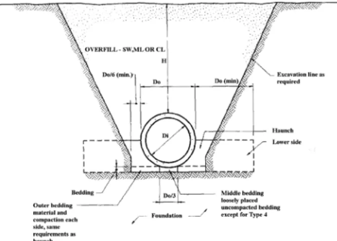
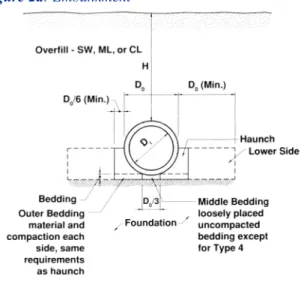
The finite element model prescribes definitive trench configurations (refer to Figure 1) and measurable levels of compaction (refer to Table 1).
Table 1:Compaction Requirements...continued on next page
Table 1:Compaction Requirements
STANDARD TRENCH INSTALLATION SOILS AND MINIMUM COMPACTION REQUIREMENTS
Installation Bedding Thickness Haunch and Lower Side
Type Outer Bedding
1 Do/24 minimum, 95% SW 90% SW
not less than 75mm. 95% ML,
If rock foundation, or 100% CL
use Do/12 minimum, not less than 150mm.
2 Do/24 minimum, 90% SW or 85% SW or not less than 75mm. 95% ML 90% ML or
If rock foundation, 95% CL
use Do/12 minimum, not less than 150mm.
3 Do/24 minimum, 85% SW, 85% SW,
not less than 75mm. 90% ML or 90% ML or If rock foundation, 95% CL 95% CL use Do/12 minimum,
not less than 150mm.
4 No bedding required, No compaction No compaction except if rock foundation, required, except required, except
use Do/12 minimum, if CL, use 85% if CL,use 85% CL not less than 150mm.
•
where Dois the outer diameter of the pipe•
SW are well-graded material (sands, gravels etc.)•
ML are inorganic silts, fine sands or clayey silts with slight plasticity•
CL are inorganic clays of low to medium plasticity, gravelly clays, sandy clays etc.Bedding Considerations for Concrete Pipe
SIDD bedding allows for a range of installation options from high quality granular bedding to the use of native materials. The bedding design is left to the designer, who is able to determine the most appropriate installation design for the project under consideration. This decision shall be based on a combination of issues, such as project location, ultimate use of infrastructure, site conditions, availability of materials and installation cost. The design-er is given the ability to ‘design’ the project through the use of PipePac.
Inspection, Unloading & Storage of Concrete Pipe
Metric Conversions for Mass:
1 kilogram (kg) = 2.205 pounds 1 pound = 0.4536 kilograms (kg)
1 metric tonne = 1000 kilograms (kg) = 2205 pounds = 1.1023 short tons 1 short ton = 2000 pounds = 907.2 kilograms (kg) = 0.9072 metric tonnes
INSPECTION:
•Concrete pipe should be inspected on the truck when it first arrives at the jobsite before it is unloaded to ensure that no damage has occurred during transit. Damaged or missing items must be reported at this time.
•It is important to check that the pipe is the correct size and class, and that it is supplied with the proper gas-ket.
•All components of any lifting assembly must comply
with the requirements of the Regulations for Construction Projects (Ontario Regulation 213/91) made under the Occupational Health and Safety Act.
•A competent person designated by the contractor
should inspect all lifting assemblies and attachment hardware prior to each use. Any damaged or defective equipment must be immediately removed from serv-ice.
• All other safety procedures and recommended operat-ing practices by the manufacturer of the liftoperat-ing equip-ment must be followed.
UNLOADING:
The work procedures for material handling, worker safe-ty, and the modification of backhoes, loaders and fork lifts for use as cranes or similar hoisting devices must comply with the relevant sections of the Ontario Regulation 213/91 made under the Occupational Health and Safety Act.
• Pipe should be unloaded on a level site using the
appropriate lifting equipment.
• Capacities of lift assemblies, devices, forklifts and cranes should be checked before unloading.
• Small diameter pipe up to and including 250mm diam-eter come palletized and require lift forks to properly support the pallet.
• Pipe up to and including 900 mm diameter can be
unloaded using the automatic tailgate unloader, pro-vided timber is placed under the pipe barrels to protect the bells from impact when unloading on hard ground or pavement.
• Wood planks should be placed between pipes as they
are rolled off a tailgate to prevent impact damaga with-an adjacent pipe.
• When using forklift equipment, care must be taken to ensure the inside of the pipe is not gouged or damaged. Wooden planks should be used to ensure the forks do not come in direct contact with the pipe.
Inspection, Unloading & Storage of Concrete Pipe
• Pipe 975 mm diameter and larger provided with an
anchor or a lift hole, must be lifted off the truck deck using proper lifting devices with sufficient lifting capacity.
• Pipe should be unloaded as close to the trench as pos-sible to reduce handling, and placed on the trench side away from the excavated material.
• Section 6 of the OCPA Concrete Pipe Design Manual
details the installation of pipe, including handling and stockpiling.
The preceding list of procedures may vary slightly for the precast manufacturers; therefore the contractor should confirm these methods or alternatives for unloading with their precast supplier. In addition, it is the responsibility of the contractor to ensure compliance with the Occupational Health and Safety Act and the construction project regula-tions.
STORAGE:
• Pipe should be stored as close to the trench as possible. • Pipe should be placed on planks to prevent them from becoming frozen to the ground in winter, and to permit ease of handling in summer. Using planks, pipe can be easily rolled and the lift cable can slide under the pipe. In addition, for pipes that have protruding bells, the boards and not the bells carry the weight of the pipe.
• The bottom layer should be placed on a level base.
Each layer of bell and spigot pipe should be arranged so that the bells are at the same end. The bells in the
next layer should be at the opposite end, and project-ing beyond the spigot of the section in the lower layer. Where there is only one layer the bells and spigots should alternate between adjacent pipe.
• All flexible gasket materials, including joint lubricat-ing compounds where applicable should be stored in a cool dry place in the summer, and prevented from freezing in the winter. Rubber gaskets and preformed mastics should be kept clean, away from oil, grease, excessive heat and out of direct sunlight.
Lifting Systems
Proprietary lifting systems are available in the Ontario concrete pipe market for pipe and maintenance holes and box culverts. They offer a positive lifting connection to the pipe for added safety and since the anchors are embed-ded, patching is not required, thus no leaks. In addition, anchors in pipe can be used to “home” or pull the product into its final position.
HANDLING PIPE
In pipe, anchors are placed laterally along the top of the pipe. These anchors can accommodate pipe diameters from 975mm to 3600mm. Because the pipe is lifted by two points, stability during lifting is established aiding in homing one pipe to the other. Once the pipe has been tem-porarily set for final placement, one of the anchors from the previously set pipe can be used to home the new piece into final alignment (refer to Illustration #1). Once again, since the anchors are embedded in the concrete wall, there is no need for patching.
HANDLING MAINTENANCE HOLES AND ACCESSORIES
In maintenance hole products, anchors are placed on the sides of the product. Unlike pipe where there are two anchors along the sides of the product, maintenance ucts have one or more anchors on either side of the prod-uct for stability during installation and stacking (refer to Illustration #2). Inserts in maintenance holes have been tested and provide a 50% increase in factor of safety as compared to conventional pin methods.
Lifting Systems
Illustration #1
Correct method for Homing Pipe Together
Note:All lifting hardware shall be fastened to all anchors to safely lift the product.
The pipe is first transported to the installation site with the symmet-rical sling and lowered close to the already placed pipe
Note:All anchor locations must be used at once to safely lift the product
To pull the pipe into position the long leg of the pipe layer is coupled to the previously placed pipes. The short leg (Eye 2) is hung into the hook provided for this purpose.
It must be ensured that the top guide pulley of the crane is over the outer lifting anchor of the previously placed pipe so that the direction of pull is slightly inclined towards the placed pipe.
When moving the jib, the pipe is now pulled into position using the precision hoisting gear.
Stop - Release - action complete
Lifting Systems
Note:Load must be applied simultaneous to all anchors in order to safely lift product.
Note:Direction of extended lip should be in the direction of lift. Illustration #2
How to Use Universal Lifting Eye for Maintenance Holes
Correct Method for Placing Lifting Eye onto Anchor
Box Culverts and Welded Wire Fabric
Precast reinforced concrete box units are accepted throughout North America as a standard, high quality, and economical product. Common sizes range from 1800x900 mm up to 3600x3600 mm, but are not restricted to these. The successful application of these large precast structures is due, in large measure, to the development of welded wire reinforcement (WWR). WWR sheets can be bent into shape as an economical replacement for rebar. Use of WWR has significantly improved production efficiencies and the quality of the finished product.
Deformed WWR with its higher yield strength of 485 MPa allows for a reduction in steel area of 17% over con-ventional 400 MPa rebar. WWR is easily bendable into rectangular cages and is readily weldable (typical Carbon Equivalent = 0.20 vs. 0.46 for weldable rebar). The close-ly spaced welded intersections of WWR result in superior crack control. A weld shear strength of 240 MPa which contributes to bond and anchorage of WWR in concrete is assured by maintaining an adequate size differential of wires being welded together. The smaller wire cross sec-tional area must be a minimum 40% of the area of the larg-er wire.
Reinforced concrete box units are covered by the standard specification OPSS 1821. The sizes of box units in OPSS 1821 (Material Specification for Precast Reinforced Concrete Box Culverts and Box Sewers) range from 1800x900 mm to 3000x2400 mm.
OPSS 1821 lists the respective steel area requirements for a full inner and outer cage made up of ‘U-shaped’ fabric
sections (refer to Table 1). Minimum perimeter steel
areas listed range from 180 to 1163 mm2/m with
typ-ical reinforcement fabric style for a 2400 x 1800 mm box size with 0.90 m of earth cover would be 51x 203 – MD38.7 x MW 19.2 and 51 x 203 – MD25.8 x MW19.2, for inner and outer cages, respectively.
OPSS 1821 requires that WWR shall achieve a minimum 4% elongation at ultimate strength measured over a 100 mm gauge length including one cross wire. WWR manu-facturers are obliged to issue a mill compliance notifica-tion to that effect. As well, OPSS 1821 recognizes that some precast producers may utilize plain WWR and there-fore only allows for Fy=450 MPa. Other standards allow for Fy=485 MPa for deformed WWR.
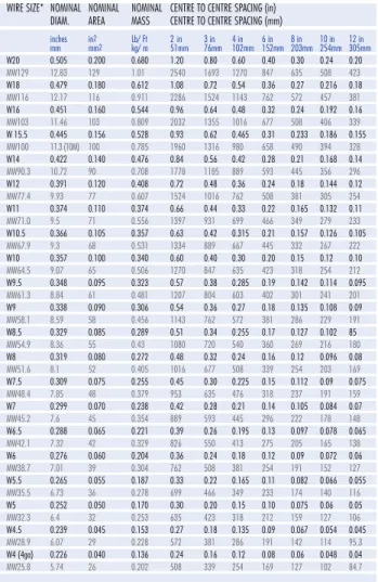
Table 1 is very useful as a design aid by listing metric wire sizes and equivalent customary inch unit wire sizes along with steel areas per unit length of pipe or box for different wire spacings.
Steel Reinforcement
Reinforcing wire cages are fabricated from premanufac-tured WWR sheets that are bent into ‘U-shaped’ fabric sections and tack welded to form square or rectangular inner and outer cages (refer to Figure 1). The wire used in WWR is produced from controlled quality, low carbon (S1006 to C1012) hot rolled steel rods. These rods are cold worked through a series of dies to reduce the rod diameter to the specified wire diameter and to improve the yield strength of the steel. A deformation roll is used to produce deformed wire. Chemical composition is care-fully selected to give proper welding characteristics in addition to desired mechanical properties. WWR is
pro-Box Culverts and Welded Wire Fabric
Box Culverts and Welded Wire Fabric
duced on automatic resistance welding machines that are designed for long, continuous operation. Longitudinal wires are straightened and fed continuously through the machine. Transverse wires, entering from the side or from above the welder, are individually welded to the longitu-dinal wires each time the longitulongitu-dinal wires advance through the machine a distance equal to one transverse wire spacing.
Wire Size Designation
Individual wire (plain and deformed) size designations are based on the cross-sectional area of a given wire. The “W” prefix is for plain smooth wire and “D” for deformed. The number following the letter gives the cross-sectional area of the wire: for customary units in hundredths of an inch. For example, W4 would indicate a plain wire with a cross-sectional area of 0.04 in2. D10 would indicate a
deformed wire with an area of 0.10 in2. When describing
metric wire or fabric a prefix “M” is added with the num-ber following the letters “MW” or “MD” denoting the steel area in metric units (mm2). For example MW 25.9
refers to a plain wire with an area of 25.9 mm2. Table 1
lists the standard W & D and equivalent MW and MD wire sizes along with steel areas per unit length of box for different wire spacing.
Table 1:Sectional Areas of
Welded Wire Reinforcement Fabric (Metric Units)
Sectional Areas of Welded Wire Reinforcement
IMPERIAL UNITS
METRIC UNITS
AREA - in2PER LINEAR FOOT / AREA - mm2PER LINEAR METRE
WIRE SIZE* NOMINAL NOMINAL NOMINAL CENTRE TO CENTRE SPACING (in)
DIAM. AREA MASS CENTRE TO CENTRE SPACING (mm)
inches in2 Lb/ Ft 2 in 3 in 4 in 6 in 8 in 10 in 12 in mm mm2 kg/ m 51mm 76mm 102mm 152mm 203mm 254mm 305mm W20 0.505 0.200 0.680 1.20 0.80 0.60 0.40 0.30 0.24 0.20 MW129 12.83 129 1.01 2540 1693 1270 847 635 508 423 W18 0.479 0.180 0.612 1.08 0.72 0.54 0.36 0.27 0.216 0.18 MW116 12.17 116 0.911 2286 1524 1143 762 572 457 381 W16 0.451 0.160 0.544 0.96 0.64 0.48 0.32 0.24 0.192 0.16 MW103 11.46 103 0.809 2032 1355 1016 677 508 406 339 W 15.5 0.445 0.156 0.528 0.93 0.62 0.465 0.31 0.233 0.186 0.155 MW100 11.3 (10M) 100 0.785 1960 1316 980 658 490 394 328 W14 0.422 0.140 0.476 0.84 0.56 0.42 0.28 0.21 0.168 0.14 MW90.3 10.72 90 0.708 1778 1185 889 593 445 356 296 W12 0.391 0.120 0.408 0.72 0.48 0.36 0.24 0.18 0.144 0.12 MW77.4 9.93 77 0.607 1524 1016 762 508 381 305 254 W11 0.374 0.110 0.374 0.66 0.44 0.33 0.22 0.165 0.132 0.11 MW71.0 9.5 71 0.556 1397 931 699 466 349 279 233 W10.5 0.366 0.105 0.357 0.63 0.42 0.315 0.21 0.157 0.126 0.105 MW67.9 9.3 68 0.531 1334 889 667 445 332 267 222 W10 0.357 0.100 0.340 0.60 0.40 0.30 0.20 0.15 0.12 0.10 MW64.5 9.07 65 0.506 1270 847 635 423 318 254 212 W9.5 0.348 0.095 0.323 0.57 0.38 0.285 0.19 0.142 0.114 0.095 MW61.3 8.84 61 0.481 1207 804 603 402 301 241 201 W9 0.338 0.090 0.306 0.54 0.36 0.27 0.18 0.135 0.108 0.09 MW58.1 8.59 58 0.456 1143 762 572 381 286 229 191 W8.5 0.329 0.085 0.289 0.51 0.34 0.255 0.17 0.127 0.102 85 MW54.9 8.36 55 0.43 1080 720 540 360 269 216 180 W8 0.319 0.080 0.272 0.48 0.32 0.24 0.16 0.12 0.096 0.08 MW51.6 8.1 52 0.405 1016 677 508 339 254 203 169 W7.5 0.309 0.075 0.255 0.45 0.30 0.225 0.15 0.112 0.09 0.075 MW48.4 7.85 48 0.379 953 635 476 318 237 191 159 W7 0.299 0.070 0.238 0.42 0.28 0.21 0.14 0.105 0.084 0.07 MW45.2 7.6 45 0.354 889 593 445 296 222 178 148 W6.5 0.288 0.065 0.221 0.39 0.26 0.195 0.13 0.097 0.078 0.065 MW42.1 7.32 42 0.329 826 550 413 275 205 165 138 W6 0.276 0.060 0.204 0.36 0.24 0.18 0.12 0.09 0.072 0.06 MW38.7 7.01 39 0.304 762 508 381 254 191 152 127 W5.5 0.265 0.055 0.187 0.33 0.22 0.165 0.11 0.082 0.066 0.055 MW35.5 6.73 36 0.278 699 466 349 233 174 140 116 W5 0.252 0.050 0.170 0.30 0.20 0.15 0.10 0.075 0.06 0.05 MW32.3 6.4 32 0.253 635 423 318 212 159 127 106 W4.5 0.239 0.045 0.153 0.27 0.18 0.135 0.09 0.067 0.054 0.045 MW28.9 6.07 29 0.228 572 381 286 191 142 114 95.3 W4 (4ga) 0.226 0.040 0.136 0.24 0.16 0.12 0.08 0.06 0.048 0.04 MW25.8 5.74 26 0.202 508 339 254 169 127 102 84.7
W3.5 0.211 0.035 0.119 0.21 0.14 0.105 0.07 0.052 0.042 0.035 MW22.6 5.36 23 0.177 445 296 222 148 110 88.9 74.1 W3 0.195 0.030 0.102 0.18 0.12 0.09 0.06 0.045 0.036 0.03 MW19.2 4.95 19 0.152 381 254 191 127 95.3 76.2 63.5 W2.9 (6ga) 0.192 0.029 0.098 0.174 0.116 0.087 0.058 0.043 0.035 0.029 MW18.7 4.88 19 368 245 184 123 91 74.1 61.4 W2.5 (7ga) 0.178 0.025 0.085 0.15 0.10 0.075 0.05 0.037 0.03 0.025 MW16.0 4.52 16 0.126 317 212 159 106 78.3 63.5 52.9 W2.1(8ga) 0.162 0.021 0.070 0.124 0.082 0.062 0.041 0.031 0.025 0.021 MW13.3 4.1 13 0.104 261 175 130 88 65.6 52.4 43.6 W1.7(9ga) 0.148 0.017 0.059 0.104 0.069 0.052 0.035 0.026 0.021 0.017 MW11.1 3.8 11 0.073 220 146 110 74.1 55 44.5 36 *Wire size:
Imperial wire sizes are designated by their sectional area in hundreths of a square inch. Metric wire sizes are designated by their sectional area in mm2
E x . for W 8 , Area = 0.08 in2 E x . for MW51.6, Area = 51.6 mm2
- W - denotes smooth wire ex.: W 1 8 - D - denotes deformed wire ex.: D 1 8 - M - denotes metric ex.: MW18 or MD18 Rebar Sizes: #3 :A = 0.11 in2= 71 mm2 10M :A = 100 mm2= 0.155 in2 #4 :A = 0.20 in2= 129 mm2 15M :A = 200 mm2= 0.31 in2 #5 :A = 0.31 in2= 199 mm2 20M :A = 300 mm2 = 0.465 in2 #6 :A = 0.44 in2= 284 mm2 25M :A = 500 mm2 = 0.775 in2 #7 :A = 0.60 in2= 387 mm2 30M :A = 700 mm2= 1.085 in2 #8 :A = 0.79 in2= 510 mm2 Mesh conversion:
Rebar Fy = 400 MPa: Deformed Mesh Fy = 485 MPa,available up to 550 MPa Area reduction when converting Rebar Steel Area to Deformed Mesh Multiply by x 400/485 = 0.825 Conversion Factors: 1 in = 25.4 mm 1 lb = 0.4536 kg 1 lb = 0.4536 kg 1 ft = 0.3048 m (Diam.inches) 2 x 2.673 = weight Lb s/ ft 1000 psi = 6.895 MPa A = 0.7854 d2 1 in2= 645.2 mm2 1 in2/ ft = 2116.7 mm2/m 1 lb/ft2= 4.882 kg /m2
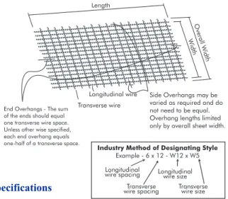
Designating Style of Welded Wire Reinforcement Fabric
Spacing and sizes of wires in WWR are identified by “style”. A typical style designation is 152 mm x 305 mm – MD77.4xMW32.3. This denotes a unit of WWR in which:
• Spacing of longitudinal wires = 152 mm • Size of longitudinal wires = 77.4 mm2 • Spacing of transverse wires = 305 mm
• Size of transverse wires = 32.3 mm2. A typical
descrip-tion of a fabric style and sheet size would be 152 mm x 305 mm – MD77.4xMW32.3 x 2337 mm + 13 mm + 13 mm x 7320 mm including 152 mm overhangs. This describes a sheet of the previous style which is 2337 mm wide plus 13 mm overhang on each side (i.e. 2363 mm overall width) with an overall length of 7320 mm, including 152 mm overhangs on each end. It is
Box Culverts and Welded Wire Fabric
Figure 1 - Precast Reinforcement Concrete Box Sections For Culverts, Storm Drains And Sewers Suggested Arrangement of Welded Wire Fabric
Inner Cage - Two Lapped "U" Shaped Sheets Outer Cage - Two Lapped
"U" Shaped Sheets
4d Minimum Radius to 10d Maximum
Wire Diameter (d)
Typical Section
Figure 1:Precast Reinforcement Concrete Box Sections for Culverts, Storm Drains and Sewers Suggested Arrangement of Welded Wire Fabric
Box Culverts and Welded Wire Fabric
important to note that the terms of longitudinal and transverse are related to the manufacturing process and do not refer to the relative position of the wires in a con-crete structure. Figure 2 provides a graphical represen-tation of the nomenclature used for welded wire fabric.
Specifications
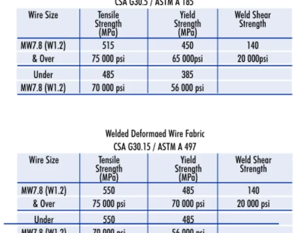
Welded Wire Reinforcement and wire for the manufacture of WWR is produced in accordance to CSA specifications as listed in Table 2. Table 3lists the minimum required mechanical properties. You will note that smooth and deformed WWR have a yield strength equal to 450 MPa and 485 MPa, respectively. Higher yield strengths, improved weldability, premanufactured quality control and fabricating efficiencies are the primary advantages of WWR over rebar. Length O ve ra llW id th W id th Transverse wire Longitudinal wire Fig 3 - Nomenclature
Side Overhangs may be varied as required and do not need to be equal. Overhang lengths limited only by overall sheet width.
End Overhangs - The sum of the ends should equal one transverse wire space. Unless other wise specified, each end overhang equals one-half of a transverse space.
Industry Method of Designating Style
Example - 6 x 12 - W12 x W5 Longitudinal
wire spacing Longitudinalwire size Transverse
wire spacing Transversewire size Length O ve ra llW id th W id th Transverse wire Longitudinal wire Fig 3 - Nomenclature
Side Overhangs may be varied as required and do not need to be equal. Overhang lengths limited only by overall sheet width.
End Overhangs - The sum of the ends should equal one transverse wire space. Unless other wise specified, each end overhang equals one-half of a transverse space.
Industry Method of Designating Style
Example - 6 x 12 - W12 x W5 Longitudinal
wire spacing Longitudinalwire size Transverse
wire spacing Transversewire size
For ASTM equivalent designs, please contact your local box culvert producer.
Box Culverts and Welded Wire Fabric
Canadian U.S. Title
Standards Specifications
CSA G 30.3 ASTM A 82 Cold-Drawn Steel Wire for Concrete Reinforcement CSA G 30.5 ASTM A 185 Welded Steel Wire Fabric for Concrete Reinforcement CSA G 30.14 ASTM A 496 Deformed Steel Wire for Concrete Reinforcement CSA G 30.15 ASTM A 497 Welded Deformed Steel Wire Fabric for Concrete Reinforcement
Welded Smooth Wire Fabric CSA G30.5 / ASTM A 185
Wire Size Tensile Yield Weld Shear Strength Strength Strength
(MPa) (MPa)
MW7.8 (W1.2) 515 450 140
& Over 75 000 psi 65 000psi 20 000psi
Under 485 385
MW7.8 (W1.2) 70 000 psi 56 000 psi
Welded Deformaed Wire Fabric CSA G30.15 / ASTM A 497
Wire Size Tensile Yield Weld Shear Strength Strength Strength
(MPa) (MPa)
MW7.8 (W1.2) 550 485 140
& Over 75 000 psi 70 000 psi 20 000 psi
Under 550 485
MW7.8 (W1.2) 70 000 psi 56 000 psi
Table 3
Connection to Concrete Pipe
New Construction
Concrete pipe fittings, which are manufactured in accor-dance with CAN/CSA A257, are recommended for new construction. Fittings, such as tees and wyes can be used for service connections, catchbasin leads and secondary lines. Pipe tees and wyes for secondary lines are manu-factured by matching the springline of both the mainline pipe with the lateral pipe. Standard catchbasin and service connections are detailed below (refer to Figure 2). For maximum wye sizes please contact your local supplier. As an alternative, maintenance hole tees and bends can be used on mainlines with a diameter greater than 1200 mm. Maintenance hole tees are manufactured by connecting a riser section directly into the mainline pipe. A pipe tee to a secondary line or a pipe bend can be installed directly downstream of the maintenance hole tee, allowing access for maintenance and operation (refer to Figure 1.1 & 1.2).
Main Line Size Max Tee Size
300 300 375 375 450 450 525 525 600 600 675 675 750 750 825 825 900 900 975 975 1050 1050 1200 1200 1350 1200 1500 1200 1650 1200 1800 1200 1950 1200 2100 1200 2250 1200 2400 1200 2550 1200 MH Tee Pipe Tee (Placed @ Spring Line)
MH Tee
Bend
Figure 1.1
Figure 1.2
Connection to Concrete Pipe
Existing Line
Concrete pipe is versatile in that additional connections can be made on site by the contractor. For smaller diam-eter pipe, the connection is made by coring a hole in the mainline pipe, then connecting the lateral pipe using an approved pipe adaptor or flexible boot. Such adaptors will provide a watertight flexible connection when prop-erly installed. For larger diameter pipe, the traditional method involves cutting the existing pipe, placing a new pipe (lateral) and then pouring a concrete collar and cradle around the connection to the first lateral joint. Care should be taken to protect the connection from possible differential loading.
45˚ Incoming pipe
Main Line Pipe
Gasket Incoming PVC Pipe (100 - 300 DIA.) Incoming PVC Pipe Bell adaptor grouted in Cored Tee
Grouted in Bell Adaptor Standard catchbasin and
Hydrogen Sulphide Production
Since sewers in Ontario have sufficient slope to maintain solids contained in the sewer stream in suspension, hydro-gen sulfide hydro-generation is usually not a significant problem here. In Ontario, the average ambient temperature is low enough during most of the year to prevent sulphide devel-opment. Industrial chemicals, that could facilitate sul-phide production, or cause corrosion directly, are moni-tored and controlled at source. In addition, sewer use bylaws contain restrictions on the discharge of deletrious substances and the discharge of wastewater with elevated temperatures to the sewer system. The goal of design engineers is to minimize the potential for the development of hydrogen sulfide in sewers. Concrete pipe can resist intermittent attacks of corrosive agents due to the manner in which it is manufactured (usually with a minimum cover of 25mm of concrete over the reinforcing steel). When there are problems in drainage systems caused by H2S, the following factors are usually the primary influ-ences that may lead to the formation of sulphuric acid in sewers.
Dissolved Sulphide:
The sulphide concentration is the limiting factor in the release of hydrogen sulphide to the sewer walls whereby corrosion may result. If metals are present in the sewage stream, a small amount of sulphide is immobilized to form insoluble metal salts. The amount varies from 0.1 to 0.3 mg/L.
pH:
The pH influences dissociation of the sulphide ion species in the sewer. At a pH of 6, more than 90% of the dissolved sulphide is hydrogen sulphide. At a pH of 8, less than 10% is in the form of hydrogen sulfide.
Biological Oxygen Demand (BOD) and Temperature:
Temperatures above 15˚ Celsius may contribute to the generation of hydrogen sulphide if all other conditions of sulphide generation are present.
BOD is a measure of the oxygen depletion by the decom-position and mineralization of organic matter. In a sewer system, the conversion of sulphates to sulphide requires energy. The BOD determination is a measure of the ener-gy within the system that will facilitate this conversion. The BOD usually occurs over a 5 day period and has thus become known as the 5-day BOD.
Velocity:
Velocity affects the rate of oxygen absorption, the release of hydrogen sulphide to the atmosphere, and the build up of solids. The minimum velocity of the sewer stream should be between 0.61 and 1.07 m/s to keep solids in sus-pension. If the velocity causes turbulent flow conditions, increased oxygen may be absorbed into the wastewater, but hydrogen sulphide in wastewater will also be released to the atmosphere. The released hydrogen sulphide may cause corrosion to the wall of the concrete pipe.
Hydrogen Sulphide Production
Time:
The continuous flow of sanitary sewage is the best defense in the fight against hydrogen sulphide production. Delay in the flow decreases the velocity, thus increasing the risk of production of H2S
Designers must guard against these risks when consider-ing the design of sanitary sewage facilities.
Junctions:
Junctions are important because the wastewater from the tributaries may contain high concentrations of sulphide, lower ph, high BODs and higher temperatures. All of these factors may affect the hydrogen sulphide production in the main sewer line. Junctions may also affect the type of flow wherever they enter the main. If the flow is turbu-lent, more oxygen may be absorbed into the wastewater, or more hydrogen sulphide may be released into the atmosphere. Since the effects of corrosion outweigh the increase in oxygen absorption, the junctions should enter the main in a manner that reduces turbulence.
Forcemains and Siphons:
Special junctions like forcemains and siphons, have a similar effect on the wastewater stream, as do regular junctions. Forcemains and siphons may flow at low veloc-ities, or intermittently, allowing the increase of sulphide. Forcemains usually flow full, which also facilitates the build-up of sulphides due to the anaerobic conditions in the forcemain. When forcemains and siphons enter the main sewer, the higher concentration of sulphide may cause problems further downstream.
Ventilation:
Ventilation is not an effective measure to reduce the cor-rosion of concrete pipe because it is difficult to prevent condensation on the walls of pipe due to temperature vari-ations. The hydrogen sulphide is oxidized in the aerobic layer on the wall of the pipe to form sulphuric acid which may corrode the pipe as it trickles down the wall of the pipe.
If velocities of 0.61 metres per second and oxygen levels of 1 milligram per litre and temperatures less than 15˚ Celsius can be achieved, corrosion in sanitary sewers will not be problem at any time.
Accumulation of solids could be a problem during the three warmest months of the year. During these months, temperature is sufficiently high to have sewer water tem-peratures above 15˚C. The elevated temtem-peratures would also decrease the dissolved oxygen. Dissolved oxygen is inversely proportional to temperature of the water. if effective BOD levels are less than 600 milligrams per litre and the effective slope is 0.2% and flow is 0.085 cubic metres per second, sulphide concentrations will not increase sufficiently to become a problem.
Service Life of Pipe Materials Organic and Inorganic
Today, with emphasis being placed on pipeline rehabilita-tion, many government agencies are evaluating the service life performance of their systems. Sometimes these eval-uations key in on obvious design flaws relating to inherent problems such as leaking joints. To properly evaluate old pipe, consideration should be given to the standard speci-fications and manufacturing techniques in existence at the time the pipe was made. Today, concrete pipe manufac-tured in Ontario uses rubber gasketed joints with very close tolerances. Concrete pipe should not be viewed as inferior to any modern pipe materials based on observa-tion of old mortar joint pipe. In fact, investigaobserva-tions of many old concrete pipe installations have demonstrated excellent durability with increased strength and superior abrasion resistance in adverse environments.
Modern pipe is made from two basic types of material – organic material and inorganic material. Organic materi-als were first used for pipe during the 1800’s. Wooden barrel stave pipe has been discovered during reconstruc-tion in some Ontario cities. Today plastic replaces wood as the organic pipe material most commonly used. Unlike wood, plastic pipe contains preservatives, anti-oxidants and stabilizers, to slow down the natural gradual loss in strength that occurs with organic materials. However, the combination of stress and environment conditions may accelerate these natural changes in plastic materials. Also the use of fillers in PVC pipe can reduce the tensile strength which is critical to a flexible pipe material. Currently there is no known test to establish the service life of a PVC pipe containing filler. However, tests done on mainly small diameter tubing made of PVC without fillers, indicate statistical data that has been extrapolated to predict potential 50 year service life.
Inorganic materials such as clay and concrete have histor-ically demonstrated good durability. Samples of concrete pipe made by the Romans is an example often cited to demonstrate the claim that modern concrete pipe has proven potential to last for a least 100 years. Many tests done on old pipe discovered during reconstruction proj-ects have repeatedly confirmed that concrete pipe does increase in strength over time. Concrete pipe is unique in that it has a record of proven durability, an important fea-ture required by today’s pipe specifiers.
Chemical Resistance of Sanitary Sewers
Sanitary sewer systems are expensive, and once installed should have a service life of 100 years or more. Sanitary sewers carry substances that can be very damaging to public health and the environment. Therefore, their structural integrity should not be compromised by the substances they are designed to carry. The chemical resistance of concrete pipe makes it suitable for industri-al sanitary applications. Thermoplastic pipe materiindustri-als are not recommended for this type of use 1. Their
struc-tural integrity is limited by effluent temperatures, and their thin walls can be damaged by commonly found substances, such as detergents, vegetable oils, cleaning fluids and solvents 2.
Concrete pipe benefits from heavy walls and neutralizing materials such as limestone aggregate, which may prove advantageous for industrial sanitary sewers. It is acknowledged that acids with pH below 5.5 can damage concrete. Sewer Use Bylaw’s generally limit the dis-charge of substances to a range of pH 5 to pH 9, howev-er, substances outside of this range have found their way into sewer systems. If there is a one-time-only situation, the surface paste of the concrete pipe is affected and the exposed limestone aggregate will effectively limit dam-age. If this is an ongoing condition, damage will occur, but, due to concrete pipe’s thick walls, full penetration rarely occurs and steel reinforcement will delay any pos-sibility of structural failure. According to a 10-year study conducted by the Ohio Department of
Transportation (1982), in an aggressive environment with a pH of 4, concrete pipe will last 100 years. This quality provides a measure of assurance that service will not be suddenly interrupted, and give maintenance crews time to plan and finance any remedial work necessary.
Chemical Resistance of Sanitary Sewers
References:
(1) CSA B182.2-99: PVC Sewer Pipe and Fittings (PSM
Type) & CSA B182.6-02: Profile Polyethylene Sewer Pipe & Fittings
“Industrial waste disposal lines should be installed only with specific approval of the regulatory authority, since chemicals not commonly found in drains and sewers and temperatures in excess of 60 degrees Celsius (140 degrees Fahrenheit).”
(2) CSA B182.6-02: Profile Polyethylene Sewer Pipe and Fittings
“Industrial waste disposal lines should be installed only with specific approval of the regulatory authority, since chemicals not commonly found in drains and sewers may be encountered and temperatures in excess of 60 ˚C.”
(3) Transportation Research Board NCHRP 225, page 118
“Some of the chemicals or common materials that can attack, degrade or destroy plastic used in pipe are given below. Exposures which may accelerate stress crack-ing are designated by ‘+’.”
PVC Ketones, esters, aromatic and chlorinated hydro-carbons+ and vegetable oils+.
PE Strong oxidizing acids, oils, polar reagents such as detergents+, alcohols+, esters+, ketones+. and sili-cones+.
Steel Reinforcement for Concrete Pipe
Physical Properties of Reinforcement
Reinforcing areas required for concrete pipe, as deter-mined by pipe design methods like SIDD (Standard Installations – Direct Design), SAMM (Spangler & Marston Method) and PipeCar vary according to design factors like depth of bury, bedding types, pipe geometry, and material properties of the concrete and steel.
Areas of steel are achieved through a grid pattern of lon-gitudinal and circumferential wires. Lonlon-gitudinal wires run the length of the pipe, while circumferential wires fol-low the perimeter of the pipe. For the most part, longitu-dinal wires maintain the position and shape of the circum-ferential reinforcement wires at designed spacing within the formwork. It is by varying the wire diameter and/or the wire spacing, along with concrete strength, that a pipe achieves its design strength. Reinforcing cages can be manufactured with welded wire mesh or fabricated using cage machines or mandrels.
Principles of Reinforcement
In a loaded application, the concrete pipe wall must resist the combined effects of moment and thrust known as flex-ural stress. The resultant of this stress is circumferential tension and compression forces within the pipe wall. Taking a closer look on how the pipe performs, it is actu-ally the cross-sectional shape of the pipe that changes from round to a slightly elliptical shape. Although the movement is small, the vertical dimension decreases and the horizontal dimension increases. This change in shape produces tensile stresses at the invert and obvert of the
Steel Reinforcement for Concrete Pipe
pipe, and on the outside of the pipe at the springline. While this is occurring, compressive stresses are develop-ing in areas opposite to the tensile stresses. Flexural stress is maximized in the tensile areas of the pipe (refer to Figure 1).
Since concrete is weak in tension, steel reinforcement must be placed in these areas to control cracking. Reinforcement in
areas of compres-sion is not required, however, methods of reinforcing and ease of placement result in it being used.
Shear stresses (or diagonal tension) should also be
checked when considering the supporting strength of the concrete pipe. Once again, it is the tensile zones within the pipe wall where shear strength of the pipe is reduced. For a given pipe diameter with a fixed wall thickness, varying rein-forcement areas (within limits) and reinforce-ment placereinforce-ment provide the addi-tional shear strength to the pipe.
Four cage
con-C C C CT T T T T = Tensile Stress C = Compression Stress Original Shape Loaded Shape C C C CT T T T
Inner Circular Cage Elliptical Cage
Outer Circular Cage C C C CT T T T T = Tensile Stress C = Compression Stress Original Shape Loaded Shape C C C CT T T T
Inner Circular Cage Elliptical Cage
Outer Circular Cage
Figure 1
Steel Reinforcement for Concrete Pipe
figurations are common use: single circular cage, double circular cage, single elliptical cage, and a combination of an elliptical cage and one or more circular cages. Alternatively, quadrant reinforcement can be used to pro-vide increased steel areas in the tensile zones of the pipe. When necessary, stirrups provide the additional shear strength or radial tension strength. Figure 2illustrates a typical reinforcement pattern for large diameter pipe com-bining an inner and outer cage with an elliptical cage for optimum positioning of tensile steel.
D-Load Requirements & Manufacturing Specifications
Reinforced concrete pipe is manufactured in accordance with CSA standard CAN/CSA- A257.2-Series M92. The concrete pipe is tested and classified with a D-load using the Three-Edge Bearing (3EB) method. The D-load is the supporting strength of a pipe for an applied load expressed in Newtons per linear metre per millimetre of inside diam-eter (N/m/mm). There are two pipe strengths ddiam-etermined by this method; D0.3is a calculated pipe strength for an
applied load which will produce a crack width of 0.3 mm over a 300 mm length, while Dultis a calculated ultimate
pipe strength which will result in failure. The D-load strength concept and the statistical evaluation of test results are the basis for the CSA Standards that govern the manufacture of concrete pipe. CAN/CSA- A257.2 lists design tables for five classes of reinforced concrete pipe (ie. 40-D through 140-D) showing the pipe diameter, wall thickness, compressive strength of concrete and the amount of circumferential reinforcement required for each class. The steel areas listed are used as a guide, however, the overriding acceptance factor is the 3EB test. For some larger pipe sizes where the CSA Standard does not list
steel areas, the pipe manufacturer may employ the design methods referenced above as a guide to selecting steel areas.
Reinforced Pipe Cage
Key Factor in the Determination of Loads on Rigid Pipe
When setting out to determine the loads on rigid pipe, and hence an appropriate pipe strength selection for a given job, designers should focus on three key areas to arrive at a safe, well engineered and cost effective design:
• Site soil conditions • Installation type • Bedding type
Site Soil Conditions
For many years designers have been referring to the Ontario Provincial Standard Drawings (OPSD) "Specified Minimum Class of Pipe" tables, also known as fill height tables (807.01, 807.03 and 807.04). These tables provide a useful guideline for design in terms of rigid pipe strength selection. They have been developed based on certain assumed values, which are listed in the 'NOTES' section at the bottom of each table. The assumed values include:
• Soil density (w)
• Soil Lateral Pressure/Friction Term (kµ) • Positive projection ratio (p)
• Settlement ratio (rsd)
There are also implied values for live load type and lateral pressure fraction. Most importantly, note 'F' of OPSD 807.03 states that: "Conditions other than this should be calculated from first principles".
It is important that designers endeavor to use soils data rele-vant to their particular site. Failure to do so may lead to either over or under classifying of the pipe strength required on site.
Key Factor in the Determination of Loads on Rigid Pipe
Installation Type
There are six common installation types: Negative Projecting Positive Projecting
Confined Trench Jacked or Tunneled
Zero Projecting Wide Trench acting
Key Factor in the Determination of Loads on Rigid Pipe
The selection of an installation type will be determined, in part, by the type and condition of soils encountered on site as well as the proximity of existing services and structures to a proposed sewer line.
The classification of soils as per section 226 of Ontario Regulation 213/91 of the Occupation Health and Safety Act may promote or negate the use of a certain installation type. Further, due to uncontrolled site conditions and the installation on ancillary drainage facilities, i.e. mainte-nance holes, service connections, catchbasins, etc., and the level of effort provided in the construction of said facilities, the OCPA recommend the use of Positive Projecting design be used for concrete pipe installations.
Bedding Type
The selection of an appropriate bedding type, generally as per OPSD 802.03 series or one of the 4 SIDD types, will influence the load supported by an installed pipe as well as the cost of bedding material and the frequency of inspection required. The designer should weigh the cost of upgrading the strength of pipe to any offset in the total cost of bedding material resulting from a change in bed-ding type specification. This will yield the most cost effec-tive pipe envelope design for a given site.
Design Aids
The OCPA offers free software to aid in the design and cost calculations for pipe selection. PipePac incorporates the new SIDD method as well as the traditional SAMM (Spangler and Marston Method) to determine the loads on pipe, and CAPE (Cost Analysis of Pipe Envelope) to com-pare the cost of the entire pipe installation.
Maintenance Hole Selection Guidelines
This guideline is to assist designers in the proper sizing and selection of precast concrete maintenance holes (MH). These maintenance holes are manufactured accord-ing to the provisions of CAN/CSA A257.
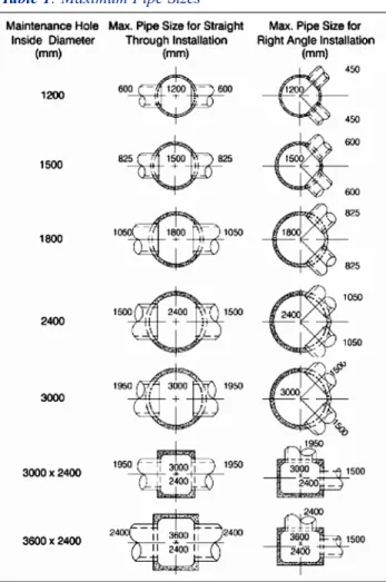
After specifying sewer sizes, designers must consider the overall efficiency of the system by selecting the appropri-ate MH. Choosing the right maintenance hole assures proper hydraulic efficiency at intersections, grade changes and elevation changes. The pipe orientation (straight through, right angle, etc.) determines the diameter of the MH required for safe handling and installation.
Maintenance Hole Selection Table
Through the continued efforts of precast concrete manu-facturer's, contractors and consulting engineers in Ontario,
Table 1was created. This table should be used to deter-mine maximum pipe sizes entering MH and for pipe open-ing configurations.
Table 1 shows some considerations for a MH including area required to accommodate the pipe openings and the benching.
Other Considerations
There are several other sizing considerations: • the vertical location of pipes (Figure 1); • safety landings (Figure 2);
Maintenance Hole Selection Guidelines
Significant Advancements in Maintenance Holes
For many years, concrete MH producers in Ontario have supplied pre-benched MH’s. Previously, benching was completed in the field to the OPSD construction standard. There are significant benefits of pre-benching including:
• the exacting standards in a manufacturing environ-ment (to OPSD 706.010) - pre-benched MH's come to the site ready to drop into place thus installation is quick and easy.
•less time and effort on site - no wasted benching materials.
• worker safety - there's no need to enter a confined space.
• little disruption to traffic and no added costs in labour and equipment.
For further information on any of these selection guidelines, go to www.ocpa.com
1500 min 1 Figure 3 F 1800 mm 1800 mm Min. Min. 1800 mm Min. Figure 2
ection guidelines, go to www.ocpa.com
Figure 4 (Plan View)
Min Cover (x) Min Cover (x) Min Cover (x) MH Dia MH Dia MH Dia Figure 1 Figure 1 Figure 2
Maintenance Hole Selection Guidelines
Maintenance Hole Selection Guidelines
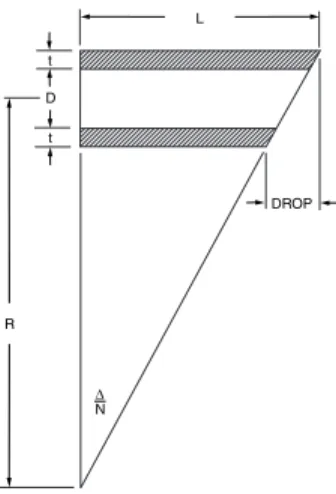
Drop Structures
Drop structures are used where there may be a change in grade, pipe size, wet site conditions or to prevent water scouring of the MH. Currently, drop structures are creat-ed using an assembly of pipe junctions and fittings attached externally to the MH using steel reinforcing and encased in concrete. There is, however, a better way. The internal drop has been used primarily as an alternative to rehabilitating existing MH’s for new connections (refer to Figure 3). The major difference is the upsizing of the MH structure in order to accommodate the diameter of the drop pipe. The advantages? Ease and safety of instal-lation and the ability to inspect and clean out the drop pipe after installation. See information provided in this guide for more details on internal drop structures.
Maintenance Hole Tees
In large pipe runs (1200 mm diameter or greater), it is pos-sible to gain access to main line through a riser section teed directly into the mainline pipe called a maintenance hole tee (MH tee). Small incoming pipes can also be teed directly into the mainline pipe just downstream from the MH tee. This replaces a standard MH installation with a combination of tees for access and operation. Figure 4
illustrates, in plan view, the spacing for lateral and the MH feed riser section.
Maintenance Hole Selection Guidelines
OCPA Concrete Pipe Information Booklet - 47
-Lateral Line
Main Line
F
Figure 4 (Plan View)
Min Cover (x) Min Cover (x) Min Cover (x) 1200 min 1500 min 1200 Sections Figure 3 F 1800 mm 1800 mm Min. Min. 1800 mm Min. Figure 2 Figure 3
Jacking Pipe
Background
Precast Reinforced Concrete Pipe is the most commonly used pipe material for jacking operations. Concrete Pipe is frequently installed by the jacking method where deep installations are necessary or where conventional open-cut excavation and backfill methods may not be feasible. Concrete pipe for jacking installations first became evi-dent in the North America in 1896 when Northern Pacific Railroad utilized this procedure for installing drainage systems under their rail lines. In more recent years, this technique has been applied to sewer construction where intermediate shafts along the line of the sewer are used as jacking stations. Reinforced bell and spigot concrete pipe as large as 3350mm diameter has been successfully installed by the jacking method.
Jacking Procedure
The initial procedure in jacking concrete pipe is to equip the leading edge of the pipe with a shield to protect the miners. This method is known as hand mining, a process where a person physically removes soil from in front of the pipe being jacked. As the material is removed on a small rail and trolley system installed in the bottom of the pipe, the pipe is jacked forward filling the void of the removed material. Material is trimmed with care and the excavation does not precede the jacking operation more than is necessary. Such procedures usually result in min-imum disturbance of the natural soils adjacent to the pipe. This method of pipe installation is very reliant on stable native soils and therefore soil data for the proposed proj-ect is critical. (Projproj-ects with loose native soils or soils
affected by ground water should not consider hand mining for pipe installation. This type of installation may be more suited to a directional drilling method for pipe installation) Contractors occasionally find it desirable to coat the out-side of the pipe with a lubricant, such as bentonite, to reduce the frictional resistance between the pipe and the soil. In most instances, this lubricant is pumped through special fittings installed in the wall of the pipe. It is desir-able to continue jacking operations 24 hours per day until completed, because of the tendency of jacked pipe to set when forward movement is interrupted, for as little as a few hours, resulting in significantly increased frictional resistance to subsequent movement. If continuous jacking cannot be accomplished, then the additional forces neces-sary to move a pipe at rest must be taken into considera-tion when designing the jacking pipe installaconsidera-tion
It is important that the direction of jacking be carefully established prior to beginning the operation. This requires the installation of guide rails in the bottom of the jacking pit or shaft. In the case of large pipe it is desirable to have such rails carefully set in a concrete slab as the weight of the large pipe may induce some settlement into native soil. The number and capacity of the jacks used depend prima-rily upon the size and length of the pipe to be jacked and the type of soil encountered. The shaft thrust walls must be strong enough and large enough to distribute the max-imum capacity of the jacks against the soil behind the thrust wall.
Loads on Jacked Pipe
Two types of loads are imposed on reinforced concrete pipe installed by the jacking method. The axial load due to
Jacking Pipe
Jacking Pipe
the jacking pressures applied during jacking process and the bearing load due to the earth cover. Live loading may also be a consideration depending on the project site and the depth of the pipe installation.
Axial Loads:For axial loads normally encountered, it is necessary to provide uniform distribution of the load around the periphery of the pipe to prevent localized stress concentrations. This is accomplished by assuring that the pipe ends are parallel and within the tolerances prescribed by CSAA257.2. Furthermore, utilization of a cushion mate-rial such as solid core plywood or hardboard in conjunction with an experienced contractor will ensure that the jacking force is properly distributed through the jacking frame and parallel to the axis of the pipe. The cross-sectional area of the concrete pipe is more that adequate to resist pressures encountered in any normal jacking operation.
It is always a good idea to meet with the jacking contractor to ascertain the jacking forces he expects to apply to the pipe. For projects where extreme jacking pressures are anticipated, due to long jacking distances or excessive unit frictional forces, concrete compressive strength higher than standard may be required, along with greater care in avoid-ing bearavoid-ing stress concentrations. A factor of safety on axial load capacity shall be 3.20 based on the ultimate strength of the concrete. The effect of eccentric or concentrated loads on the pipe joints should also be evaluated.
The magnitude of the anticipated axial loads is a function of many factors including installation technique, total length of jack, pipe skin friction, and pipe diameter. The total jack-ing force (Fjs) of concrete pipe is dependent on several
• Cross sectional area of pipe at weakest point: (Aj) • Compressive strength of concrete: (f’c)
• Appropriate factor of safety: (S.F.)
The rated jacking pipe force, (direct compression force), (Rjs) conforms to the following equation:
Rjs = Aj x f’c / S.F.
Additionally, longitudinal bending due to the eccentricity of the load on the joint face should be evaluated. In gen-eral the complete pipe remains in compression, despite minor bending due to eccentricity between the center of the joint face and the gross wall section beyond the joint. With some joint designs, the resultant force is acting con-siderably off the centerline of the wall, creating a net ten-sile stress. In such cases, this stress should be limited to 3 x fc1/2.
Lateral Loads: These loads can be a result of jacking force being applied to the pipe, if the jacking frame is not square to the end of the concrete jacking pipe. Another area where lateral pressure occurs is if the pipe is off line and /or grade, and the contractor adjusts the direction of the pipe to realign to the proper line and grade. This action subjects the bell and spigot ends of the pipe to extreme shear loads.
Earth and Live Loads:The calculation of the required pipe strength is determined by: the soil depth, soil mass, and the live load, if applicable. The Ontario Concrete Pipe Association’s software program PipePac, can assist in determining the load bearing capacity required of the pipe.
Jacking Pipe
Jacking Pipe
Two other factors need to be addressed; the dimension of the overcut on the outside of the reinforced concrete jack-ing pipe, and whether this area is grouted or not grouted after pipe installation. Once the overcut is determined the PipePac program allows for load calculations based on grouted or non-grouted conditions.
Pipe Characteristics
Materials: Requirements for cement, aggregates, rein-forcing steel, and other additives shall be as specified in the appropriate CSA material standards.
Manufacture:Reinforced concrete pipe shall be manu-factured according to CSA A257.2 Reinforced Circular Concrete Culvert, Storm Drain, Sewer Pipe, and Fittings, with attention being given to: nominal dimensions, pipe lengths, and the compressive strength of the concrete. At no time shall the compressive strength of the concrete be less than 40 Mpa.
Jacking pipe shall contain two cages of circular reinforce-ment in the barrel of the pipe. The outer cage shall extend into the groove of the pipe, and the inner cage shall extend into the tongue of the pipe. (refer to OPSS 1820 Material Specifications for Concrete Pipe).
The pipe will be manufactured with circular reinforcing cages only. At no time is elliptical steel reinforcement allowed in jacking pipe.
Should conditions warrant, the owner may request the groove end to be strengthened by the use of an external band of hot rolled steel, (12 gauge thick, and 203 mm in
height). The steel band is welded to the outside reinforcing cage with the use of appropriate spacers.
Lubrication (bentonite) ports are generally installed at the time of manufacture, and may or may not involve the use of a one way valve. It is best to check with the jacking con-tractor to locate these ports where they will work best for him.
Joints in the pipe should be as symmetrical as possible; that is, the thickness of the tongue should be as close as possible to the thickness of the groove end. Gasket options for jack-ing pipe include ‘O’ Rjack-ing or sjack-ingle offset since these gasket types are not affected by small movements in the joint area expected as jacking pressure is applied and relaxed. Subaqueous lubricant should also be supplied with the pipe.
Permissible Variation
CSA A257.2 Reinforced Circular Concrete Culvert, Storm Drain, Sewer Pipe, and Fittings provides the user with min-imum requirements for pipe variations. Users should contact the concrete pipe supplier to determine how the manufactur-er ensures the dimensional limitations are met.
Internal Diameter: The internal diameter of 1200 mm to 3000 mm reinforced concrete pipe shall not vary more from the design diameter than +/- 1% or +/- 10 mm, whichever is less.
Outside Diameter: The external diameter of 1200 mm to 3000 mm reinforced concrete pipe shall not vary more from the design diameter than +/- 1% or +/- 10 mm, whichever is less.
Jacking Pipe
Wall Thickness: At any location along the length of the pipe, or at any point around its circumference, the wall thickness shall not vary by more than +/- 5% or 5 mm, whichever is greater.
Roundness: The outside diameter of the pipe shall not vary from a true circle by more than 1%. The out of round dimensions shall be one half the difference between the maximum and minimum diameter of the pipe at any one location along the barrel.
Taper: The outside barrel of the pipe shall not vary in taper from the spigot end to the bell end by more than 3 mm.
Pipe Length: Finished pipe length shall not deviate from the design length by more than +/- 5 mm/m; with a maxi-mum variance of +/- 10 mm in any length of pipe. Length of Two Opposite Sides: Variations in the laying length of two opposite sides of the pipe shall not be more than 5 mm for any size of pipe.
End Squareness: End squareness across outside diame-ters shall govern over lengths of two opposite sides.
1200 – 1500 mm 4.4 mm variation
1650 - 2250 mm 5.5 mm variation
Entry Permit Protocol
WHY IS IT IMPORTANT TO ESTABLISH AN ENTRY PERMIT PROTOCOL FOR CONFINED SPACES?
The law requires that confined spaces be identified and certain action taken before anyone may enter a confined space.
What is Confined Space?
The Ontario Occupational Health & Safety Act Regulations for Industrial establishments define confined space as a space in which, because of its construction, location, contents or work activity therein, the accumula-tion of a hazardous gas, vapour, dust or fume or the cre-ation of an oxygen-deficient atmosphere may occur. Examples of confined spaces include the following:
• Completely enclosed structures with limited access, such as maintenance holes, storage tanks, tank cars and other vessels and chambers entered through a maintenance hole;
• Deep structures that may have an open top but require special means of entry and provision for emergency exits, such as tanks, lopping pits, bins, excavations, etc.;
• Other enclosed spaces include boilers, furnace flues, ducts, sewers, tunnels, pipelines, etc.
There are four main dangers in confined spaces: oxygen deficiency and oxygen enrichment; fire or explosion; tox-icity; and, drowning in liquids or free flowing solids. If there is a chance that hazardous vapours, dust, gas, or fumes exist in the confined spaces, the air must be tested and the area ventilated.
Under the Occupational Health and Safety Act Ontario Regulation 213/91 amended to O.Reg. 527/00 for Construction Projects, the following conditions apply for Confined Space under Part II - General Construction. For regulations on Excavations, please reference Part III of the Occupational Health and Safety Act.
Section 60 states:
(1)No worker shall be present in a confined space on a project unless,
(a)there is a means of egress from the parts of the con-fined space that are accessible to workers;
(b) all mechanical equipment in the confined space is disconnected from its power source and locked out; (c) all pipes and other supply lines in the confined space
whose contents are likely to create a hazard are blanked off; and
(d)the confined space is certified in accordance with subsection (3) to be safe for workers. O. Reg. 213/91, s. 60 (1).
(2)A competent worker shall test and evaluate a con-fined space before a worker enters it to determine whether it is free from hazard to a worker while the worker is present in it and as often as necessary to ensure that it remains free from hazard. O. Reg. 213/91, s. 60 (2).
(3)The worker who performs the tests shall certify in writing whether the confined space may endanger a worker. O. Reg. 213/91, s. 60 (3).
(4)The employer shall keep a permanent record of the results of all tests performed on a confined space. O. Reg. 213/91, s. 60 (4).
Section 61 states:
(1)No worker shall be present in a confined space in which there is or is likely to be a hazardous gas, vapour, dust, mist, smoke or fume or an oxygen con-tent of less than 18 per cent or more than 23 per cent, measured at atmospheric pressure, unless this section is complied with. O. Reg. 213/91, s. 61 (1).
(2)The confined space shall be purged and ventilated to provide an atmosphere which does not endanger workers and measures necessary to maintain the atmosphere shall be taken. O. Reg. 213/91, s. 61 (2). (3)Suitable arrangements shall be made to remove a
worker from the confined space should assistance be required. O. Reg. 213/91, s. 61 (3).
(4)When a worker is present in the confined space, another worker shall be stationed outside it. O. Reg. 213/91, s. 61 (4).
(5)If the person stationed outside the confined space is not adequately trained in artificial respiration, a per-son so trained shall be conveniently available. O. Reg. 213/91, s. 61 (5).
Section 62 states:
(1)Despite subsections 60 (1) and 61 (1), a worker may be present in a confined space that is not purged and ventilated and for which no certificate under subsec-tion 60 (3) has been given if this secsubsec-tion is complied with. O. Reg. 213/91, s. 62 (1).