1 2 3
Technical Specification
4OCC 1.0
5 6 7 8OCC 1.0 Reference Architecture with SDN and
9
NFV Constructs
10 11 12 13 14September, 2015
15 16OCC 1.0 © The Open Cloud Connect 2015. Any reproduction of this document, or any portion thereof, shall contain the
17
Disclaimer 18
19
The information in this publication is freely available for reproduction and use by any recipient 20
and is believed to be accurate as of its publication date. Such information is subject to change 21
without notice and the Open Cloud Connect (OCC) is not responsible for any errors. The OCC 22
does not assume responsibility to update or correct any information in this publication. No rep-23
resentation or warranty, expressed or implied, is made by the OCC concerning the completeness, 24
accuracy, or applicability of any information contained herein and no liability of any kind shall 25
be assumed by the OCC as a result of reliance upon such information. 26
27
The information contained herein is intended to be used without modification by the recipient or 28
user of this document. The OCC is not responsible or liable for any modifications to this docu-29
ment made by any other party. 30
31
The receipt or any use of this document or its contents does not in any way create, by implication 32
or otherwise: 33
a)any express or implied license or right to or under any patent, copyright, trademark or trade 34
secret rights held or claimed by any OCC member company which are or may be associated 35
with the ideas, techniques, concepts or expressions contained herein; nor 36
b)any warranty or representation that any OCC member companies will announce any product(s) 37
and/or service(s) related thereto, or if such announcements are made, that such announced 38
product(s) and/or service(s) embody any or all of the ideas, technologies, or concepts con-39
tained herein; nor 40
c)any form of relationship between any OCC member companies and the recipient or user of this 41
document. 42
43
Implementation or use of specific Cloud Ethernet standards or recommendations and OCC speci-44
fications will be voluntary, and no company shall be obliged to implement them by virtue of par-45
ticipation in the Cloud Ethernet Forum. The OCC is a non-profit international organization ac-46
celerating industry cooperation on Cloud Ethernet technology. The OCC does not, expressly or 47
otherwise, endorse or promote any specific products or services. 48
49
© The Open Cloud Connect 2015. All Rights Reserved. 50
Table of Contents
52List of Contributing Members ... ii 53
1. Introduction ... 1 54
2. Terminology and Acronyms... 1 55
3. Summary of OCC 1.0 Architecture ... 5 56
4. Summary of The NFV Architecture ... 12 57
5. Mapping Between NFV and OCC Reference Architecture Constructs ... 17
58
6. Basic NFV Components of OCC Architecture ... 19
59 6.1. NFV Components of cSUI ... 19 60 6.2. NFV Components of cSC and cSCTPs... 24 61 6.3. NFV Components of cSI ... 27 62
6.4. NFV Components of cSC Crossing two cSPs ... 31
63
7. Summary of Software-Defined Networking (SDN) Architecture ... 36
64
8. OCC Management Architecture Basic Blocks ... 39
65 References ... 42 66 67
List of Figures
68Figure 1: Cloud Service Actors ... 5 69
Figure 2: Cloud Service Provider access via the standard interface, cSUI. ... 6
70
Figure 3: Cloud Provider and Cloud Carrier belong to two different Operators ... 7
71
Figure 4: cSC between two Cloud Provider entities. ... 7 72
Figure 5: Two Cloud Service Providers collectively providing Cloud Services ... 8
73
Figure 6 : Protocol Stacks that can be supported at external interfaces ... 8 74
Figure 7: Multiple VM sharing a cSC ... 9 75
Figure 8: VM supporting multiple cSIs, virtual network interface controllers (vNICs), MACs,
76
virtual networks (VNs) and IP addresses. ... 10 77
Figure 9: VM supporting ... 10 78
Figure 10: Cloud Service Connection Types ... 11 79
Figure 11: Network Layering and interface of NFV ... 12 80
Figure 12: VM Interface ... 13 81
Figure 13: Bare Metal Server Interface [2] ... 13 82
Figure 14: Bare Metal Server Interface [4] ... 14 83
OCC1.0 © The Open Cloud Connect 2015. Any reproduction of this document, or any portion thereof, shall contain the Page ii Figure 15: SWA-1 Interface ... 14 84
Figure 16: SWA-5 Interface ... 15 85
Figure 17: Container Interface ... 15 86
Figure 18: Management of Network Functions ... 16 87
Figure 19: NFV Orchestrator interaction with EMS and OSS/BSS [6] ... 16
88
Figure 20: Cloud User Interface-NaaS architecture with NFV constructs ... 17
89
Figure 21: Bare Metal Server Interface and Naas ... 18 90
Figure 22: VM access over NaaS ... 19 91
Figure 23: VNFs and Infrastructure for cSC and cSCTP ... 20 92
Figure 24: VNF and Infrastructure Components of cSC between cSUI and cSI ... 28
93
Figure 25: VNFs for cSC-csp and cSC-csp-TP ... 32 94
Figure 26: ONF SDN Architecture [10] ... 37 95
Figure 27: ITU-T SDN Architecture [11] ... 37 96
Figure 28: IETF SDN Architecture [12] ... 38 97
Figure 29: SDN Building Blocks [7] ... 39 98
Figure 30: Cloud Services Management with Life Cycle Orchestration ... 41
99
Figure 31: Management of Cloud Services provided by multiple Cloud Service Operators ... 41
100
Figure 32: Product and Service Operations Lifecycle Stages [9] ... 42 101
102
List of Tables
103Table 1: Terminology and Acronyms ... 4 104
Table 2 : Mapping between OCC and NFV Constructs ... 17 105
Table 3 : VNF and Infrastructure Components of cSUI defined in [1] ... 24
106
Table 4 : VNF and Infrastructure Components of of cScTP defined in [1] ... 26
107
Table 5 : VNF and Infrastructure Components of cSC defined in [1] ... 27
108
Table 6 : VNF and Infrastructure Components of cSI defined in [1] ... 31
109
Table 7 : VNF and Infrastructure Components of cSPcSPI defined in [1] ... 34
110
Table 8 : VNF and Infrastructure Components of cSC-csp-TP defined in [1] ... 36
111 112
List of Contributing Members
113Author and Editor: Mehmet Toy, Ph.D, Comcast
114
Contributing CEF member companies agreed to be listed:
115 Avaya 116 Alcatel-Lucent 117 Verizon 118 Wedge Networks 119 Veryx 120 121 122 123
1. Introduction
124The purpose of this document is to describe possible implementations of Cloud Services Archi-125
tectures using Software-Defined Networking (SDN) and Network Functions Virtualization 126
(NFV) constructs. 127
2. Terminology and Acronyms
128This section defines the terms used in this document. In many cases, the normative definitions to 129
terms are found in other documents. The third column in Table 1 is used to provide the reference 130
for the definitions. 131
132
Terms Definitions Reference
cCcPI Cloud Carrier Cloud Provider Interface OCC 1.0 Ref.
Arch.[1] Cloud Consumer A person or organization that maintains a business
rela-tionship with and/or uses service from a Cloud Service Provider via a Cloud Service User Interface (cSUI).
OCC 1.0 Ref.
Arch.[1]
Cloud Service User A person or organization that maintains a business rela-tionship with and/or uses service from a Cloud Service Provider via a Cloud Service User Interface (cSUI).
OCC 1.0 Ref.
Arch.[1]
cC Cloud Carrier (cC) is an intermediary that provides con-nectivity and transport between Cloud Providers and Cloud Consumers or between Cloud Providers.
OCC 1.0 Ref.
Arch.[1]
CoS Class of Service MEF 10.3 [14]
CoS ID Class of Service Identifier MEF 23.1 [22]
cP Cloud Provider is an entity that is responsible for mak-ing cloud applications available to Cloud Consumers (Cloud Service Users).
NIST Special Publi-cation 500-291 [13]
cSC Cloud Service Connection OCC 1.0 Ref.
Arch.[1]
cSC-c Cloud Carrier Connection OCC 1.0 Ref.
Arch.[1]
cSC-p Cloud Provider Connection OCC 1.0 Ref.
OCC 1.0 © The Open Cloud Connect 2015. Any reproduction of this document, or any portion thereof, shall contain the Page 2 cSC-cp The segment of cSC within the boundaries of a Cloud
Service Provider where cSC crosses multiple Cloud Ser-vice Providers
OCC 1.0 Ref.
Arch.[1]
cSC-csp Cloud Service Provider Connection OCC 1.0 Ref.
Arch.[1]
cSC-csp-TP Cloud Service Provider Connection Termination Point OCC 1.0 Ref. Arch.[1]
cSC-cp-TP Cloud Carrier-Provider Connection Termination Point OCC 1.0 Ref. Arch.[1]
cSCTP (Cloud Service Connection Termination Point)
A logical entity that originates or terminates cSC at a logical user or machine interface.
OCC 1.0 Ref.
Arch.[1]
cSI Cloud Service Interface (cSI) is the interface of a Cloud Service application supporting entity of a Cloud Provid-er such as VM.
OCC 1.0 Ref.
Arch.[1]
cSO Cloud Service Operator is an operator that provides a part of the end-to-end Cloud Service which is provided by a Cloud Service Provider.
OCC 1.0 Ref.
Arch.[1]
cSP (Cloud Service Provider)
An entity that is responsible for the creation, delivery and billing of cloud services, and negotiates relation-ships among Cloud Providers, Cloud Carriers, Cloud Service Operators, and Cloud Consumers. It is the single point of contact for the consumer.
OCC 1.0 Ref.
Arch.[1]
cSPcSPI Cloud Service Provider Cloud Service Provider Interface OCC 1.0 Ref. Arch.[1]
cSUI Demarcation Point between a Cloud Consumer and
Cloud Service Provider.
OCC 1.0 Ref.
Arch.[1]
DoS Denial of Service RFC4732
DSCP Differentiated Service Code Point RFC 2474 [17]
EMS Element Management System
ENNI External Network Network Interface MEF 4 [16]
EVC Ethernet Virtual Connection MEF 10.3 [14]
EPL Ethernet Private Line MEF 6.2 [19]
Hypervisor A software, firmware or hardware running on a server that enables creation of virtual machines and runs them.
OCC 1.0 Ref. Arch.[1]
ICMP Internet Control Message Protocol RFC 792 [23]
IPSec ESP Internet Protocol Security Encapsulating Security Pay-load
RFC 4303 [24]
L2CP Layer Two Control Protocol MEF 10.3 [14]
E-Line An Ethernet Service Type that is based on a Point-to-Point EVC.
MEF 6.2 [19]
E-LAN An Ethernet Service Type that is based on a Multipoint-to-Multipoint EVC.
MEF 6.2 [19]
LAN Local Area Network IEEE 802-2 [18]
LSO Life Cycle Service Orchestration MEF 50 [21]
LSP Label-switched Path MPLS
Architec-ture[29]
MAC Media Access Control IEEE802-2 [18]
NE Network Element
NFV Network Functions Virtualization Draft ETSI GS
NFV-INF V0.3.1 [2]
NID Network Interface Device MEF 4 [16]
OSS/BSS Operation Support System/Billing Support System
PW ID Pseudowire Identification RFC 4447 [31]
REST API Representational State Transfer Application Program-ming Interface
RFC 6690 [25]
SDN Software-Defined Networking ONF White Paper
[10]
S-VLAN Service VLAN (also referred to as Provider VLAN) IEEE802.1Q [15]
TCP-AO Transmission Control Protocol- Authentication Option RFC5925 [26]
TCP SYN Transmission Control Protocol Synchronize RFC793 [27]
TLS Transport Layer Security RFC5246 [28]
OCC 1.0 © The Open Cloud Connect 2015. Any reproduction of this document, or any portion thereof, shall contain the Page 4
VM Virtual Machine OCC 1.0 Ref.
Arch.[1]
VN Virtual Network
VNF Virtualized Network Function Draft ETSI GS
NFV-INF 001
V0.3.12 [4]
VNIC Virtual Network Interface Controller
Table 1: Terminology and Acronyms 133
135
3. Summary of OCC 1.0 Architecture
1136
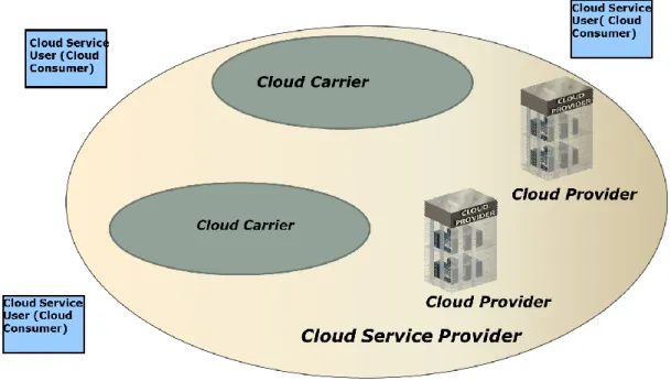
The key actors of the OCC architecture for Cloud Services are depicted in Figure 1 [1] where a 137
Cloud Service Provider is responsible for providing an end-to-end Cloud Service to a Cloud Ser-138
vice User (i.e. a customer of Cloud Service Provider) using one or more Cloud Carrier(s) and 139 Cloud Provider(s). 140 141 142 143 144
Figure 1: Cloud Service Actors
145
A Cloud Consumer interfaces to a Cloud Service Provider (cSP)’s facilities via a standards inter-146
face called Cloud Service User Interface (cSUI) (Figure 2) which is the demarcation point be-147
tween the Cloud Service Provider and the Cloud Consumer. 148
When the Cloud Provider (cP) and the Cloud Carrier (cC) are two independent entities belonging 149
to two different operators as depicted in Figures 3 and 4, the standards interface between them is 150
called cCcPI (Cloud Carrier Cloud Provider Interface). In this case, a cSC for cloud services can 151
be terminated at either cCcPI or cSI. 152
153
1 This section copies figures and text from OCC 1.0 Reference Architecture. The Reference Architecture takes
OCC 1.0 © The Open Cloud Connect 2015. Any reproduction of this document, or any portion thereof, shall contain the Page 6 154
155
156
Figure 2: Cloud Service Provider access via the standard interface, cSUI.
157 158 159 160 161 162 163 164 165 166 167
168
Figure 3: Cloud Provider and Cloud Carrier belong to two different Operators
169
170
171
172
Figure 4: cSC between two Cloud Provider entities.
173
It is also possible for two or more cSPs to be involved in providing a cloud service to a Cloud 174
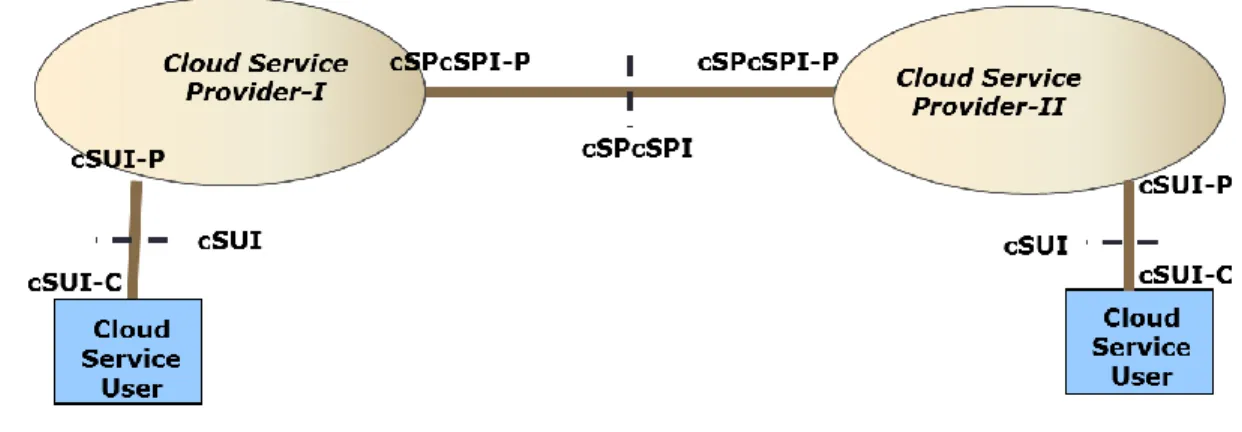
Consumer as depicted in Figure 5 where two cSPs interface to each other via a standards inter-175
OCC 1.0 © The Open Cloud Connect 2015. Any reproduction of this document, or any portion thereof, shall contain the Page 8 face called Cloud Service Provider Cloud Service Provider Interface (cSPcSPI). In this scenario, 176
only one of the cSPs needs to interface to the end user, coordinate resources and provide a bill. 177
The cSP that does not interface to the end user is called Cloud Service Operator (cSO)2. 178
179
180 181 182
Figure 5: Two Cloud Service Providers collectively providing Cloud Services
183 184 185
So far we have identified interfaces between user and cSP, between cSPs, between cP and cC, 186
between NaaS [1] and Cloud Service application supporting entity which is cSI. The protocol 187
stack at each interface that can be supported is depicted in Figure 6. Each of the protocol layers 188
may be further decomposed into their data, control and management plane components. 189 190 191 192 193 194
Figure 6 : Protocol Stacks that can be supported at external interfaces 195
2 The cSO is a cSP that is not responsible for the end-to-end service. It can be a cP or a cC or an entity providing
only cloud applications with cSI. It is possible that cSO may provide a bill for its part of the service, but this bill is not a bill for the end-to-end service that can be provided by the cSP.
196 197
The cSC provides connectivity between two or more cSCTPs. The cSC could be an EVC, LSP 198
or IP VPN connection. 199
200
A cSC can support accessing multiple VMs via multiple sessions as depicted in Figure 7 where a 201
virtual switch routes traffic to a destination VM. 202
203
204 205
Figure 7: Multiple VM sharing a cSC 206
207
Furthermore, a VM may consist of multiple virtual network interface controllers (VNICs) where 208
each VNIC can be identified by a soft MAC address, as depicted in Figure 8. In this case, a 209
VNIC interface may map to a cSI. 210
OCC 1.0 © The Open Cloud Connect 2015. Any reproduction of this document, or any portion thereof, shall contain the Page 10 211
212
Figure 8: VM supporting multiple cSIs, virtual network interface controllers (vNICs), MACs,
213
virtual networks (VNs) and IP addresses 214
215
The cSI can be supported by a container providing virtualization as depicted in Figure 9. It is 216
also possible to support cSI without a virtualization platform. 217 218 219 220 Figure 9: VM supporting 221 222
Cloud service connection types are depicted in Figure 10. The connection can be between two 223
termination points of a cSP. If the connection crosses multiple cSPs, the connection segment 224
within a cSP is called Cloud Service Provider Connection (cSC-csp). If the connection crosses a 225
cP and cC, the connection segment within the cP is called Cloud Provider Connection (cSC-p) 226
and the connection segment within the cC is called Cloud Carrier Connection (cSC-c). 227
229 230 231 232 233 234 235 236 237 238 239 240 241 242 243 244 245
(a) cSC between two termination points residing on the resources of one cSP 246
247 248
249 250
(b) cSC between two termination points residing on the resources of two different cSPs 251
(i.e. one of them is acting as a cSO) 252
253
254 255
(c) cSC between a termination point residing on cC and a termination point residing 256
on a cP 257
Figure 10: Cloud Service Connection Types
258 259
OCC 1.0 © The Open Cloud Connect 2015. Any reproduction of this document, or any portion thereof, shall contain the Page 12
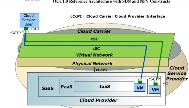
4. Summary of The NFV Architecture
260
NFV [2, 3] divides the network into two layers, Network Hardware (or Infrastructure) and Virtu-261
al Network (or Virtual Network Function) as depicted in Figure 11 below. Furthermore, NFV 262
represents each system component as a functional block. The interactions between blocks are 263
represented as interfaces. 264
(Vn-Nf)/VN interface is identified as the virtual interface for the network. The Line and E-265
LAN services of MEF are being considered as examples of (Vn-Nf)/VN. 266
267
Figure 11: Network Layering and interface of NFV
268
NFV also identifies a VM interface [2] as (Vn-Nf)/VM or Vn-Nf-VM, which the OCC Reference 269
Architecture refers to as the cSI. Given there is no description of (Vn-Nf)/VM in [2], we consid-270
er it to be an equivalent of cSI. 271
272 273
274 275
Figure 12: VM Interface
276 277
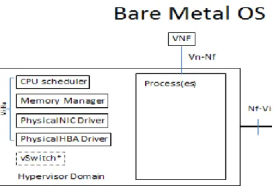
NFV identified an interface to hardware [4] as Vi-Ha and interface to Bare Metal OS as depicted 278
in Figures 13 and 14. This interface can be a subset of cSUI or cCcPI or cSPcSPI. 279
280
Figure 13: Bare Metal Server Interface [2] 281
OCC 1.0 © The Open Cloud Connect 2015. Any reproduction of this document, or any portion thereof, shall contain the Page 14 283
284
Figure 14: Bare Metal Server Interface [4]
285 286
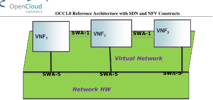
NFV identifies SWA (Software Architecture)-1 interface [5] as depicted in Figure 15 to enable 287
communication between various network functions within the same or different network service. 288
They may represent data and/or control plane interfaces of the network functions (VNF, Physical 289
Network Function-PNF). SWA-1 can be an equivalent of the virtual component of MEF UNI. 290
291
Figure 15: SWA-1 Interface
292
NFV identifies SW-5 interfaces which are an abstraction of all sub-interfaces between the NFV 293
Infrastructure (NFVI) and the VNF, including VNF inter-switch connectivity services such as E-294
LAN, E-Line [5], as depicted in Figure 16. 295
296 297
298 299
Figure 16: SWA-5 Interface
300 301
NFV divides functional blocks as Host Functional Block (HFB) and Virtualization Functional 302
Block (VFB) [30, 32] as depicted in Figure 17. The interface between HFB and VFB is called 303
Container Interface which is the virtual interface between two containers. 304
305
306 307
Figure 17: Container Interface 308
309 310
VNFs are managed by the “Management and Orchestration Function” [4] (Figure 18). The in-311
teraction of this orchestrator with Element Management System (EMS) and OSS/BSS [6] is de-312 picted in Figure 19. 313 314 315 316
OCC 1.0 © The Open Cloud Connect 2015. Any reproduction of this document, or any portion thereof, shall contain the Page 16 317
318 319
Figure 18: Management of Network Functions
320 321
322 323
Figure 19: NFV Orchestrator interaction with EMS and OSS/BSS [6]
324 325
5. Mapping Between NFV and OCC Reference Architecture Constructs
326327
Given there is no formal or informal descriptions of NFV interfaces in ETSI/NFV documents, it 328
is difficult to map the constructs. Table 2 and the following figures describe the recommended 329
mappings between NFV and OCC architectural constructs. 330
331 332
Architectural Construct NFV Construct OCC Construct
User Interface (Vi-Ha)+(Vn-Nf)/VN cSUI
VM Interface (Vn-Nf)/VM cSI
Container Interface Container Interface cSI
SWA-1 Software Architecture-1 cSI
Cloud Carrier-Cloud Provider Interface cCcPI
Cloud Service Provider-Cloud Service Provider Interface
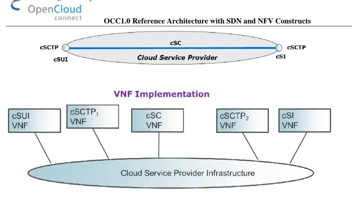
cSPcSPI Connection between Users or between a
User and VM or between VMs
VNF Forwarding Graph cSC
Connection Termination Point cSCTP
333
Table 2 : Mapping between OCC and NFV Constructs
334 335
NaaS and Cloud User interfaces to NaaS are depicted in Figure 20 using NFV constructs. Since 336
cSUI represents both physical and logical components of NaaS, we map the cSUI to the combi-337
nation of Vi-Ha and (Vn-Nf)/VN. 338
339
340
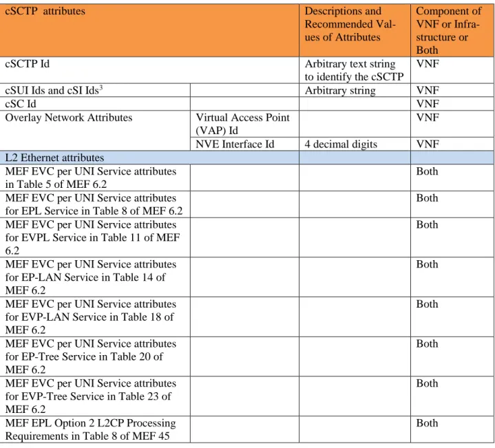
341
Figure 20: Cloud User Interface-NaaS architecture with NFV constructs
342 343 344
Cloud user access to bare metal servers over NaaS is depicted in Figure 21, using NFV con-345
structs. As described in [1], bare metal servers can interface to NaaS using cSUI or cCcPI. We 346
map this interface to the combination of Vi-Ha and SWA-5 since this interface can support both 347
physical and logical components. 348
OCC 1.0 © The Open Cloud Connect 2015. Any reproduction of this document, or any portion thereof, shall contain the Page 18 349 350 351 352 353 354
Figure 21: Bare Metal Server Interface and Naas 355
356
Cloud user access to VMs over NaaS is depicted in Figure 22, using NFV constructs where Vi-357
Ha is defined as reference point interfacing the virtualization layer to the hardware resources in-358
cluding compute and storage [3]. The functions of the cSI interface which is an equivalent of 359
(Vn-NF)/VM ride over cCcPI. Although VNF forwarding may map to cSC, there is no concept 360
of connection termination point in VNF. The End Point as depicted in [4] does not correspond to 361
a connection termination point. The End Point is more like a device such as Customer Edge 362
(CE) or an NE. 363
365
366
Figure 22: VM access over NaaS 367
368 369
6. Basic NFV Components of OCC Architecture
370371
Neither NFV nor SDN architectures define necessary interfaces between a network and its user, 372
between service providers, between a Cloud Provider and Cloud carrier. Furthermore they do not 373
have connection and connection termination concepts as mentioned before. However, it is possi-374
ble to build these Cloud Services components using VNFs and infrastructure components. 375
376
6.1. NFV Components of cSUI
377378
VNF and infrastructure components of a point-to-point cSC and its cSCTPs in support of cloud 379
services between two cSUIs are depicted in Figure 23. 380
381 382
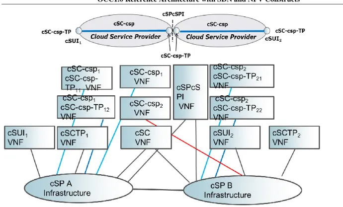
OCC 1.0 © The Open Cloud Connect 2015. Any reproduction of this document, or any portion thereof, shall contain the Page 20 383
384 385 386
Figure 23: VNFs and Infrastructure for cSC and cSCTP 387
388
In Table 3, possible NFV and infrastructure components of cSUI are identified. 389
390 391
cSUI attributes Descriptions and
Recommended Val-ues of Attributes Component of VNF or Infra-structure or Both
cSUI Id Arbitrary text string
to identify cSUI
VNF
Tenant ID ID of a tenant that
cSUI belongs to, If an overlay network is supported at this interface.
It is globally unique in a given domain and based on virtual network (VN) iden-tifier such as VLAN IDs. Multiple VN identifiers can be-long to a tenant [38].
VNF
NaaS Identifier VNF
Ethernet if supported speed, mode, physi-cal medium
Infrastructure
MAC Layer Infrastructure
DOCSIS if supported speed, mode,
physi-cal medium
Infrastructure
EPON if supported speed, physical
me-dium
Infrastructure
GPON if supported speed, physical
me-dium
Infrastructure
WDM if supported speed, physical
medium
Infrastructure
SONET/SDH if supported speed, physical
me-dium
Infrastructure Optical Transport Network
(OTN)
speed, physical me-dium
Infrastructure
Maximum Transmission Unit (MTU) > 1522 bytes Both
Connection Multiplexing Yes or No Both
Maximum number of Connection Termination Points(or End Points)
Both L2 Ethernet configuration attributes
MEF UNI Service attributes for Ethernet Private Services in Table 11 of MEF 6.2
VNF
MEF UNI L2CP Service At-tributes for UTA in Table 18 of MEF 45
VNF
MEF UNI Service attributes in Table 4 of MEF 6.2
VNF
MEF UNI L2CP Service At-tribute for vNID Case A in Table 23 of MEF 45
VNF
MEF UNI L2CP Service At-tribute for vNID Case B in Table 26 of MEF 45
VNF
MEF UNI Service attributes for EPL in Table 7 of MEF 6.2
VNF
MEF UNI Service attributes in Table 4 of MEF 6.2 MEF UNI Service attributes for EVPL in Table 10 of MEF 6.2
VNF
MEF UNI Service attributes in Table 4 of MEF 6.2
OCC 1.0 © The Open Cloud Connect 2015. Any reproduction of this document, or any portion thereof, shall contain the Page 22 MEF UNI Service attributes
for EP-LAN in Table 13 of MEF 6.2
MEF UNI Service attributes in Table 4 of MEF 6.2 MEF UNI Service attributes for EVP-LAN in Table 16 of MEF 6.2
VNF
MEF UNI Service attributes in Table 4 of MEF 6.2 MEF UNI Service attributes for EP-Tree in Table 19 of MEF 6.2
VNF
MEF UNI Service attributes in Table 4 of MEF 6.2 MEF UNI Service attributes for EVP-Tree in Table 22 of MEF 6.2
VNF
Other L2 Protocols such as Point-to-Point Protocol (PPP) and Point-to-Point Tunneling Protocol (PPTP) if supported
Both
L3 attributes if L3 protocol such as IP and/or MPLS is supported Both MPLS UNI attributes if MPLS is supported LSP ID, Pseudo-wire (PW) ID, MTU, Ingress Bandwidth Profile, Egress Bandwidth Profile, MPLS Link Down, MPLS Link Up, AIS, RDI, Lock Status Both IPv4 Address VNF DSCP Marking VNF IPv6 Address VNF IPv4 VPN[31] VNF IPv6 VPN [32] VNF L4 attributes if L4 protocols such as Transmission Con-trol Protocol (TCP), User Datagram Protocol (UDP) and Stream Control
mission Protocol (SCTP) are supported
L5 attributes if L5 protocols such as NFS, NetBios names, RPC and SQL are supported.
Both
L6 attributes if L6 protocols such as ASCII, EBCDIC, TIFF, GIF, PICT, JPEG, MPEG, MIDI are supported
Both
L7 attributes if L7 proto-cols/applications such as WWW browsers, NFS, SNMP, Telnet, HTTP, FTP are sup-ported.
Both
Operational State Enabled or
Disa-bled
VNF
Admin State Enabled or
Disa-bled
VNF Interface Level Security
ACL (Access Control List) attributes VNF
Packet Encryption IPSec
Encapsulat-ing Security Pay-load (ESP) attrib-utes Both SSL VPN (Secure Sockets Layer Virtual Private Network) Both Connection Authentication IPSec Authentica-tion Header (AH) attributes VNF TCP- Authentica-tion OpAuthentica-tion (TCP-AO) attributes VNF
Service Level Security
Rate limiting for DoS attacks: Rate limiting of TCP SYN packets and ICMP/Smurf attrib-utes.
Infrastructure
Keys for API
OCC 1.0 © The Open Cloud Connect 2015. Any reproduction of this document, or any portion thereof, shall contain the Page 24
Recurring Charges VNF
Non-recurring Charges
VNF
Table 3 : VNF and Infrastructure Components of cSUI defined in [1]
392 393
6.2. NFV Components of cSC and cSCTPs
394395
Table 4 and Table 5 identify possible NFV and infrastructure components of cSCTP and cSC. 396
397 398
cSCTP attributes Descriptions and
Recommended Val-ues of Attributes Component of VNF or Infra-structure or Both
cSCTP Id Arbitrary text string
to identify the cSCTP
VNF
cSUI Ids and cSI Ids3 Arbitrary string VNF
cSC Id VNF •
Overlay Network Attributes Virtual Access Point
(VAP) Id
•
VNF
NVE Interface Id 4 decimal digits VNF
L2 Ethernet attributes
MEF EVC per UNI Service attributes in Table 5 of MEF 6.2
Both MEF EVC per UNI Service attributes
for EPL Service in Table 8 of MEF 6.2
Both MEF EVC per UNI Service attributes
for EVPL Service in Table 11 of MEF 6.2
Both
MEF EVC per UNI Service attributes for EP-LAN Service in Table 14 of MEF 6.2
Both
MEF EVC per UNI Service attributes for EVP-LAN Service in Table 18 of MEF 6.2
Both
MEF EVC per UNI Service attributes for EP-Tree Service in Table 20 of MEF 6.2
Both
MEF EVC per UNI Service attributes for EVP-Tree Service in Table 23 of MEF 6.2
Both
MEF EPL Option 2 L2CP Processing Requirements in Table 8 of MEF 45
Both
3 cSUI Id and cSI Ids are included to identify cSUI and cSI that cSCTP is related to. The cSUI-cSCTP and
cSI-cSCTP relationships maybe represented via association in the information model instead of an attribute of the cSCTP object.
MEF EPL Option 2 L2CP Processing Recommendations in Table 9 of MEF 45
Both
Protection (via redundant cSCTP on a different physical port of the same CE or different CE at cSUI, and on a different VM at cSI)
1:1or 1+1 Both
L2 Ethernet SOAM attributes [25] Maintenance Entity Group (MEG) Id
VNF Maintenance End Point (MEP)
Id
VNF
MEP Level VNF
L3 attributes if interface is L3
IPv4 Subnet Address VNF
IPv6 Subnet Address VNF
DSCP Mapping VNF
Bandwidth Profile CIR Both
CBS Both
EIR Both
EBS Both
Protection (via redundant cSCTP on a different port of the
same CE or different CE providing
the cSUI, and on a different VM of
the application entity providing cSI)
1:1or 1+1 Both
LSP Label VNF
EXP Mapping VNF
Operational State Enabled or Disabled Infrastructure
Administrative State Enabled or Disabled VNF
cSCTP Level Security
Packet encryption IPSec ESP VNF
SSL VPN VNF
Connection Authentication IPSec AH VNF
TCP-AO VNF
Data confidentiality/privacy Logical separation of cSTPs, limiting DoS and excessive resource consump-tion via rate limit-ing
OCC 1.0 © The Open Cloud Connect 2015. Any reproduction of this document, or any portion thereof, shall contain the Page 26 Service Level Security Rate limiting of
DoS attacks and excessive resource consumption
Infrastructure
Table 4 : VNF and Infrastructure Components of of cScTP defined in [1]
399 400 401
cSC attributes Descriptions and
recom-mended values of attributes
Component of VNF or Infrastructure or Both
cSC Id Arbitrary text string to
iden-tify the cSC
VNF
List of associated cSCTP Ids4 VNF
Overlay Network Attributes VNI ID • VNF
Type Point-to-Point VNF Point-to-Multipoint VNF Multipoint-to-Multipoint VNF
Protection 1:1 or 1+1 cSC needs to be protected
for path protection
VNF
L2 Ethernet connection attributes [71,47] MEF EVC Service attributes
in Table 6 of MEF 6.2
Both MEF EVC Service attributes
of EPL in Table 9 of MEF 6.2
Both
MEF EVC Service attributes of EVPL in Table 12 of MEF 6.2
Both
MEF EVC Service attributes of EP-LAN in Table 15 of MEF 6.2
Both
MEF EVC Service attributes of EVP-LAN in Table 18 of MEF 6.2
Both
MEF EVC Service attributes of EP-Tree in Table 21 of MEF 6.2
Both
MEF EVC Service attributes of EVP-Tree in Table 24 of MEF 6.2
Both
MEF EVC Perfromance attributes and Parameters
Both
4 cSCTP Ids are included to identify termination points associated with this cSC. This cSC-cSCTP relationship may
per CoS in Table 25 of MEF 6.2
L3 connection attributes (if supported)
Service Level Objectives (SLOs)
Delay, jitter, loss Both
MTU Both
Type Point-to-Point,
Multipoint-to-Multipoint, Rooted Mul-tipoint
VNF
Connection Start Time Specified in seconds in
Co-ordinated Universal Time (UTC).
VNF
Connection Start Interval (Start Interval pa-rameter to indicate the acceptable interval after the Start Time during which the service attribute modifications can be made.) [80]
Specified in seconds in UTC
VNF
Connection Duration Specified in days, minutes
or seconds.
VNF
Connection Period Specified in daily, weekly
or monthly
VNF
Operational State Enabled or Disabled Infrastructure
Administrative State Enabled or Disabled VNF
Billing Options Monthly,
Hourly
VNF
402
Table 5 : VNF and Infrastructure Components of cSC defined in [1]
403 404
6.3. NFV Components of cSI
405406
VNF and infrastructure components of a point-to-point cSC and its cSCTPs in support of cloud 407
services between a cSUI and a cSI are depicted in Figure 24. 408
OCC 1.0 © The Open Cloud Connect 2015. Any reproduction of this document, or any portion thereof, shall contain the Page 28 410 411 412 413
Figure 24: VNF and Infrastructure Components of cSC between cSUI and cSI
414 415
Table 6 identifies possible NFV and infrastructure components of cSI. 416
417
cSI attributes Descriptions and Recommended
Values of Attribute
Component of VNF or Infrastructure or Both
cSI Id Arbitrary text string to identify
cSI
VNF
VM ID
http://www.ietf.org/id/draft-ietf-opsawg-vmm-mib-00.txt
[53] uses 128-bit Universally Unique ID (UUID) [36] as a unique identifier for a VM in an administrative region.
VNF
List of NaaS List of NaaS employing this VM
or server (i.e. application entity is shared or dedicated)
VNF
Interface Protection 1+1 or 1:1 or None
Connection Multiplexing Yes or No
Maximum number of Connection Termination Points Both
L2 Ethernet configuration attributes[17, 71, 66]
MEF UNI Service attrib-utes in Table 4 of MEF 6.2
Both
utes for EPL in Table 7 of MEF 6.2
MEF UNI Service attrib-utes in Table 4 of MEF 6.2
MEF UNI Service attrib-utes for EVPL in Table 10 of MEF 6.2
Both
MEF UNI Service
attrib-utes in Table 4 of MEF 6.2 MEF UNI Service
attrib-utes for EP-LAN in Table 13 of MEF 6.2
Both
MEF UNI Service
attrib-utes in Table 4 of MEF 6.2 MEF UNI Service
attrib-utes for EVP-LAN in Table 16 of MEF 6.2
Both
MEF UNI Service attrib-utes in Table 4 of MEF 6.2
MEF UNI Service attrib-utes for EP-Tree in Table 19 of MEF 6.2
Both
MEF UNI Service attrib-utes in Table 4 of MEF 6.2
MEF UNI Service attrib-utes for EVP-Tree in Ta-ble 22 of MEF 6.2
Both
Other L2 Protocols such as Point-to-Point Protocol (PPP) and Point-to-Point Tunneling Protocol (PPTP) if supported
Both
VM Protection (if support-ed)
This would be redun-dant VM or redunredun-dant server or redundant resource offering the service
OCC 1.0 © The Open Cloud Connect 2015. Any reproduction of this document, or any portion thereof, shall contain the Page 30
VM Portability5 Yes or No VNF
L3 attributes if L3 protocol such as IP and MPLS are supported
MPLS UNI attributes [49] if MPLS is support-ed
LSP ID, PW ID, MTU, Ingress Bandwidth Profile, Egress Band-width Profile, MPLS Link Down, MPLS Link Up, AIS, RDI, Lock Status Both IPv4 Address VNF DSCP Marking Infrastructure IPv6 Address VNF IPv4 VPN VNF IPv6 VPN VNF NAT VNF
L4 attributes if L4 protocols such as Transmission Control Protocol (TCP), User Datagram Protocol (UDP) and Stream Control Transmission Protocol (SCTP) are supported
VNF
General Ports 32111 (TCP) VNF
9427 (TCP) VNF
PCoIP (PC over IP) Ports 50002(TCP/UDP) VNF
4172 (TCP/UDP) VNF
RDP (Remote Desktop Protocol) Ports
3389 (TCP) VNF
Connection server Ports 4001 (TCP) VNF
L5 attributes if L5 protocols such as NFS, Net-Bios names, RPC and SQL are supported.
VNF
L6 attributes if L6 protocols such as ASCII, EBCDIC, TIFF, GIF, PICT, JPEG, MPEG, MIDI are supported
VNF
L7 attributes if L7 protocols/applications such as WWW browsers, NFS, SNMP, Telnet, HTTP, FTP are supported.
VNF
Operational State Enabled or Disabled Infrastructure
Admin State Enabled or Disabled VNF
Security
5 VM Portability is being able to move VM to another site/zone or moving data/applications from one server to
an-other. A VM could be moved across different hypervisors, such as VMware's ESXi, the Apache Software Founda-tion's Xen, Microsoft's Hyper-V and the open source KVM (kernel-based virtual machine).
SSL (Secure Socket Lay-er) Termination
Terminating SSL traffic for services such as load balancer
VNF
ACL VNF
Packet encryption IPSec ESP
(Encapsu-lating Security Pay-load)
Both
SSL VPN VNF
Connection Authentication IPSec AH VNF
TCP-AO VNF
Service Level Security Rate limiting of
DoS attacks and ex-cessive resource consumption
Both
Data confidentiali-ty/privacy
Prevent tenants from eavesdropping on each other via logi-cal separation
VNF
Session Layer Security REST API
(Repre-sentational State Transfer Application Programming Inter-face) over SSL (Se-cure Sockets Layer) /TLS (Transport Layer Security)
VNF
API keys VNF
Billing Recurring Charges VNF
Non-recurring Charges
VNF
418
Table 6 : VNF and Infrastructure Components of cSI defined in [1]
419 420 421
6.4. NFV Components of cSC Crossing two cSPs
422423
VNF and infrastructure components of a point-to-point cSC crossing two cSPs and its cSCTPs in 424
support of cloud services between two cSUIs are depicted in Figure 25. 425
426 427
OCC 1.0 © The Open Cloud Connect 2015. Any reproduction of this document, or any portion thereof, shall contain the Page 32 428
429 430
Figure 25: VNFs for cSC-csp and cSC-csp-TP 431
432
Table 7 identifies possible NFV and infrastructure components of cSPcSPI. 433
434
cSPcSPI attributes Descriptions and
Recommended At-tribute Values Component of VNF or Infra-structure or Both
cSPcSPI Id Arbitrary text string
to identify the cSPcSPI
VNF
Name of cSPs interfacing each other Arbitrary text string
to identify the cSP
VNF Physical Interface
L2 Ethernet Infrastructure
speed, mode, phys-ical medium
• •
MAC Layer Infrastructure •
DOCSIS if supported speed, physical me-dium
Infrastructure EPON if supported speed, physical
me-dium
Infrastructure GPON if supported speed, physical
me-dium
Infrastructure
dium
SONET/SDH if supported speed, physical me-dium
Infrastructure Optical Transport Network (OTN)
Infrastructure
MTU > 1522 bytes Both
Connection Multiplexing Yes or No VNF
Maximum number of Connection Termination Points (or End Points)
VNF L2 Ethernet configuration attributes[20,22]
MEF ENNI Service attributes in Table 2 of MEF 26.1
Both MEF ENNI L2CP Service Attributes for
Access EPL in Table 17 of MEF 45
Both MEF ENNI L2CP Service Attributes for
UTA in Table 20 of MEF 45
Both MEF ENNI L2CP Service Attributes for
vNID Case A in Table 25 of MEF 45
Both MEF ENNI L2CP Service Attributes for
vNID Case B in Table 28 of MEF 45
Both L2 Ethernet SOAM attributes [25]
Maintenance Entity Group (MEG) Id
VNF Maintenance End Point
(MEP) Id VNF MEP Level VNF Maintenance Intermedi-ate Point (MIP) Id VNF
LAG MEG Both
LAG Link MEG VNF
Operator MEG VNF
Other L2 Protocols such as Point-to-Point Protocol (PPP) and Point-to-Point Tunneling Protocol (PPTP) if support-ed
Both
L3 attributes if L3 protocol such as IP and MPLS are sup-ported
MPLS UNI attributes if MPLS is su-ported LSP ID, PW ID, MTU, Ingress Bandwidth Pro-file, Egress Bandwidth Pro-file, MPLS Link Down, MPLS Link Up, AIS, RDI, Lock Status
OCC 1.0 © The Open Cloud Connect 2015. Any reproduction of this document, or any portion thereof, shall contain the Page 34
Fast Reroute Both
NAT VNF
IPv4 Subnet Address VNF
IPv6 Subnet Address VNF
DSCP Marking Infrastructure
IPv4 VPN [31] VNF
IPv6 VPN [32] VNF
Security between cSPs (if supported)
ACL VNF
Packet encryption IPSec ESP Both
SSL VPN VNF
Connection Authentication IPSec AH VNF
Service Level Security Rate limiting of
DoS attacks and excessive re-source consump-tion
Both
435
Table 7 : VNF and Infrastructure Components of cSPcSPI defined in [1]
436 437
Table 8 identifies possible NFV and infrastructure components of cSC-csp-TP. 438
439
cSC-csp-TP attributes Descriptions and
Recommended Val-ues of Attributes Component of VNF or Infra-structure or Both
cSC-csp-TP Id Arbitrary text string
to identify the cSC-csp-TP
VNF
cCScSPI Ids VNF •
Overlay Network Attributes Virtual Access Point
(VAP) Id
•
VNF
NVE Interface Id 4 decimal digits VNF
L2 Ethernet attributes
MEF OVC End Point per ENNI Ser-vice Attributes in Table 17 of MEF 26.1
Both
MEF OVC End Point per UNI Service Attrib-utes in Table 18 of MEF 26.1
Both MEF OVC L2CP Service Attributes
for Access EVPL in Table 13 of MEF 45
Both
MEF OVC L2CP Service Attributes
for Access EPL in Table 16 of MEF 45
Both
for UTA in Table 19 of MEF 45 MEF OVC L2CP Service Attributes for vNID Case A in Table 24 of MEF 45
Both
OVC L2CP Service Attributes for vNID Case B in Table 27 of MEF 45
Both
Protection (via redundant cSC-csp-TP on a different port of the same cSPcSPI Gateway
1:1or 1+1 Both
MEF OVC End Point per ENNI Ser-vice Attributes in Table 17 of MEF 26.1
Both
MEF OVC End Point per UNI Service Attrib-utes in Table 18 of MEF 26.1
Both
L2 Ethernet SOAM attributes [25] VNF
Maintenance Entity Group (MEG) Id
VNF Maintenance End Point (MEP)
Id
MEP Level
Maximum Number of MEPs VNF
Maintenance Intermediate Point (MIP) Id
VNF L3 attributes if interface is L3
IPv4 Subnet Address VNF
IPv6 Subnet Address VNF
DSCP Mapping Both
Bandwidth Profile CIR Both
CBS Both
EIR Both
EBS Both
Protection (via redundant cSCTP on a different port of the same cSPcSPI Gateway
1:1or 1+1 Both
LSP Label
EXP Mapping
Operational State Enabled or Disabled
Administrative State Enabled or Disabled VNF
cSC-csp-TP Level Security
Packet encryption IPSec ESP VNF
SSL VPN VNF
Connection Authentication IPSec AH VNF
TCP-AO VNF
Service Level Security Rate limiting of DoS attacks and limiting excessive
OCC 1.0 © The Open Cloud Connect 2015. Any reproduction of this document, or any portion thereof, shall contain the Page 36 resource
consump-tion
Data confidentiality/privacy Preventing eaves-dropping between cSC-csp-TPs via logical separa-tion.
Infrastructure
440
Table 8 : VNF and Infrastructure Components of cSC-csp-TP defined in [1]
441 442
7. Summary of Software-Defined Networking (SDN) Architecture
443444
Software-Defined Networking (SDN) is defined by ONF as an emerging architecture that is dy-445
namic, manageable, cost-effective, and adaptable [10]. This architecture decouples the network 446
control and forwarding functions (Figure 26) enabling the network control to become directly 447
programmable and the underlying infrastructure to be abstracted for applications and network 448
services. 449
450
Abstracting the control plane from the network elements allows network-platform-specific char-451
acteristics and differences that do not affect services to be hidden. In addition, applications can 452
request needed resources from the network via interfaces to the control plane. 453
454
ITU-T keeps the ONF layer separation and adds orchestration between application layer and con-455
trol layer as depicted in Figure 27 to provide automated control and management of network re-456
sources and coordination of requests from the application layer [11]. 457
458
The IETF also keeps the ONF layer separation (Figure 28) and adds a management plane which 459
is responsible for monitoring, configuring, and maintaining network devices, in parallel to con-460
trol plane [12]. 461
462 463
464
Figure 26: ONF SDN Architecture [10]
465 466
467 468
Figure 27: ITU-T SDN Architecture [11]
OCC 1.0 © The Open Cloud Connect 2015. Any reproduction of this document, or any portion thereof, shall contain the Page 38 470 471 472 473 474 475
Figure 28: IETF SDN Architecture [12] 476
SDN building blocks are summarized in Figure 29. The application layer sits on top of services 477
layers. The services layer interacts with an orchestrator which can interact with multiple control-478
lers via a north bound API. The north bound interface between applications/services allows the 479
applications to authenticate and learn of which objects they have authorization to manipulate, or 480
to interact with objects belonging to controlling software. The SDN Orchestrator requests object 481
models from each of the controlling software which is responsible for managing and manipulat-482
ing them. The Southbound API provides abstraction for the controller to manage the devices in 483 its domain. 484 485 486 487
488 489
Figure 29: SDN Building Blocks [7]
490 491
8. OCC Management Architecture Basic Blocks
492493
A high level management architecture is depicted in Figure 30 and Figure 31. Applications are 494
expected to be mapped to services via a Cloud Services Catalog. For example, a voice call appli-495
cation between two users can be mapped to an Ethernet Virtual Private Line (EVPL) in H cate-496
gory [8]. The Cloud Orchestrator configures the EVPL between two users by translating this re-497
quest to appropriate commands to NFV Orchestrator and Controllers via “North Bound API”. 498
OCC 1.0 © The Open Cloud Connect 2015. Any reproduction of this document, or any portion thereof, shall contain the Page 40 The NFV Orchestrator is expected to perform service chaining of VNFs and infrastructure com-500
ponents associated with virtualized Network Elements (NEs) while Controllers automate provi-501
sioning of non-virtualized components of the network. It is possible to have non-SDN NEs in 502
the network. They will be managed by Element Management Systems (EMSs). 503
504
The Cloud Orchestrator may perform Life Cycle Service Orchestration (LSO) as described in [9] 505
for each service ordered and provisioned via User Portal and Operation Support System/Billing 506
Support System (OSS/BSS). Some of the LSO functionalities are as depicted in Figure 32: 507
Market Analysis and Product Strategy 508
Service and Resource Design 509
Launch products 510
Marketing Fulfillment Response 511
Sale Proposal and Feasibility 512
Capture Customer Order 513
Service Configuration & Activation 514
End-to-End Service Testing 515
Service Problem Management 516
Service Quality Management 517
Billing and Revenue Management 518
Terminate Customer Relationship 519
520
In Figure 30, a Cloud Orchestrator performs Life Cycle Orchestration for Cloud services by a 521
Cloud Service Operator. On the other hand, in Figure 31 where multiple operators are involved 522
in providing cloud services, multiple Cloud Orchestrators might perform Life Cycle Orchestra-523
tion. In this case, a Cloud Orchestrator of the Cloud Service Provider which is responsible from 524
the end-to-end service [1] is expected to perform Life Cycle Orchestration end-to-end. 525
526 527 528
529 530
Figure 30: Cloud Services Management with Life Cycle Orchestration 531
532 533
534 535
Figure 31: Management of Cloud Services provided by multiple Cloud Service Operators
536 537 538
The management architectures and distribution of management functionalities among layers in 539
Figure 30 and Figure 31 are examples. Further architectural details need to be worked by OCC 540 Technical Committee. 541 542 543 544 545 546
OCC 1.0 © The Open Cloud Connect 2015. Any reproduction of this document, or any portion thereof, shall contain the Page 42 547
548
Figure 32: Product and Service Operations Lifecycle Stages [9]
549 550 551
References
552[1] OCC, “OCC 1.0 Reference Architecture”, December, 2014. 553
[2] Draft ETSI GS NFV-INF V0.3.1 (2014-05), “Network Functions Virtualisation; Infra-554
structure Architecture; Architecture of the Hypervisor Domain” 555
[3] DGS NFV-INF003 V0.34 (2014-11-18), “Network Functions Virtualisation; Part 556
1:Infrastructure Architecture; Sub-Part 3: Architecture of Compute Domain” 557
[4] Draft ETSI GS NFV-INF 001 V0.3.12 (2014-11), “Network Functions Virtualisation; 558
Infrastructure Overview” 559
[5] Draft ETSI GS NFV-SWA 001 v0.2.4 (2014-11), “Network Functions Virtualisation; 560
Virtual Network Functions Architecture” 561
[6] ETSI GS NFV-MAN 001 v1.1.1 (2014-12), Network Functions Virtualisation (NFV); 562
Management and Orchestration 563
[7] M. Toy. “Cable Networks, Services and Management”, J. Wiley-IEEE Press, 2015. 564
[8] MEF 23.1, Carrier Ethernet Class of Service – Phase 2, January 2012. 565
[9] MEF 50, Carrier Ethernet Service Lifecycle Process Model, December 2014. 566
[10] ONF (Open Networking Foundation), “Software-Defined Networking: The New Norm 567
for Networks”, ONF White Paper, April 13, 2012. 568
[11] ITU-Y Y.3300, “Framework of software-defined networking”, 6/2014. 569
[12] RFC7426, “Software-Defined Networking (SDN): Layers and Architecture Terminolo-570
gy”, January 2015. 571
[13] National Institute of Standards and Technologies (NIST) Special Publication 500-291, 572
NIST Cloud Computing Roadmap, July 2013 573
[14] MEF 10.3 Ethernet Services Attributes Phase 3, October 2013. 574
[15] IEEE Std. 802.1Q-2011, Media Access Control (MAC) Bridges and Virtual Bridged 575
Local Area Networks (PDF; 6.0 MiB). ISBN 978-0-7381-6708-4. 576
[16] MEF 4 Metro Ethernet Network Architecture Framework Part 1: Generic Framework, 577
May 2004. 578
[17] RFC2474, K. Nichols, et al., Definition of the Differentiated Services Field (DS Field) 579
in the IPv4 and IPv6 Headers, December 1998 580
[18] ISO/IEC 8802-2:1998, Information technology - Telecommunications and information 581
exchange between systems - Local and metropolitan area networks - Specific require-582
ments - Part 2: Logical link control. 583
[19] MEF 6.2 Ethernet Service Definitions Phase 3, August 2014. 584
[20] MEF 23.1 Class of Service Phase 2 Implementation Agreement 585
[21] MEF 50, Carrier Ethernet Service Lifecycle Process Model, December 2014. 586
[22] MEF 23.1, Class of Service Phase 2 Implementation Agreement, January 2012. 587
[23] RFC 792, INTERNET CONTROL MESSAGE PROTOCOL, September 1981. 588
[24] RFC 4303, IP Encapsulating Security Payload (ESP), December 2005. 589
[25] RFC 6690, Constrained RESTful Environments (CoRE) Link Format, August 2012. 590
[26] RFC 5925, The TCP Authentication Option, June 2010. 591
[27] RFC 793, TRANSMISSION CONTROL PROTOCOL, September 1981. 592
[28] RFC 5246, The Transport Layer Security (TLS) Protocol Version 1.2, August 2008. 593
[29] RFC 3031, Multiprotocol Label Switching Architecture, January 2001. 594
[30] GS NFVINF 0007 v0.3.1 (2013-11-15), Network Function Virtualisation Infrastructure 595
Architecture: Interfaces and Abstractions. 596
[31] RFC 4447, Pseudowire Setup and Maintenance Using the Label Distribution Protocol 597
(LDP), April 2006 598
[32] ETSI GS NFV-INF 007 V1.1.1 (2014-10) Network Functions Virtualisation (NFV); In-599
frastructure; Methodology to describe Interfaces and Abstractions. 600
![Figure 14: Bare Metal Server Interface [4]](https://thumb-us.123doks.com/thumbv2/123dok_us/9325987.2414241/18.918.86.774.157.454/figure-bare-metal-server-interface.webp)