Rev. -, June 2015
OFFERING FLEXIBLE INTEGRATION AND ADVANCED
MAINTENANCE FEATURES INCLUDING DIAGNOSTICS,
MONITORING OF CHARACTERISTICS AND ABILITY TO
DEFINE DYNAMIC BEHAVIORS
AXIS CONTROLVALVES
WITH
CANOPEN INTERFACE
© 2015 Moog GmbH Hanns-Klemm-Straße 28 71034 Boeblingen Germany
All rights reserved.
No part of these operating instructions may be reproduced in any form (print, photocopies, microfilm, or by any other means) or edited, duplicated, or distrib-uted with electronic systems without our prior written consent.
Offenders will be held liable for the payment of damages.
Subject to change without notice. Telephone: +49 7031 622-0 Fax: +49 7031 622-191 E-mail: [email protected]
Table of contents
Copyright ... A
List of tables... xviii
List of figures ... xxii
1 General information ...1
1.1 About this manual ... 1
1.1.1 Reservation of changes and validity... 1
1.1.2 Completeness ... 1
1.1.3 Place of storage ... 1
1.1.4 Warranty and liability ... 1
1.1.5 Typographical conventions... 2
1.2 Structure of warning notices... 3
1.3 Selection and qualification of personnel ... 3
1.4 Further documentation for the servo valve ... 4
1.5 References ... 5
1.5.1 CAN field bus ... 5
1.5.2 Device Profile ... 5
1.6 Definitions ... 5
1.6.1 Internal resolution (iR) ... 5
1.6.2 Volume flow direction ... 5
1.6.3 Servo valve position and stage names... 6
1.7 Abbreviations... 6
1.8 Trademarks ... 7
2 Access over CANopen...9
2.1 Introduction... 9
2.2 Device profiles ... 9
2.3 CANopen slave reference model ... 10
2.4 CANopen objects... 11
2.4.1 Parameter value ... 11
2.4.2 Parameter and their attributes... 11
2.4.3 Units and prefix parameter ... 13
2.5 CANopen object dictionary (OD)... 13
2.6 CAN data link layer... 14
2.7 CAN bit rate and Node-ID configuration... 14
2.7.1 CAN bit rate and Node-ID configuration using LSS services ... 15
2.7.2 CAN bit rate and Node-ID configuration using SDO protocol... 15
2.7.2.1 Object 0x3002: Module identifier (Node-ID) ... 16
2.7.2.2 Object 0x3003: Bit rate... 16
2.8 CANopen communication protocols ... 17
2.8.1 Synchronization (SYNC) protocol (COB-ID: 0x080)... 17
2.8.1.1 Object 0x1005: SYNC protocol COB-ID configuration ... 18
2.8.2 Emergency (EMCY) protocol (COB-ID: 0x080+Node-ID) ... 18
2.8.2.1 Object 0x1014: EMCY protocol COB-ID configuration... 18
2.8.3 Process data object (PDO) protocol... 19
2.8.3.1 RxPDO protocol configuration (COB-ID: 0x200, 0x300, 0x400, 0x500).. 19
2.8.3.1.1 Object 0x1400: 1st RxPDO protocol configuration ... 20
2.8.3.1.2 Object 0x1401: 2nd RxPDO protocol configuration... 20
2.8.3.2 RxPDO mapping (COB-ID: 0x200, 0x300, 0x400, 0x500) ... 22
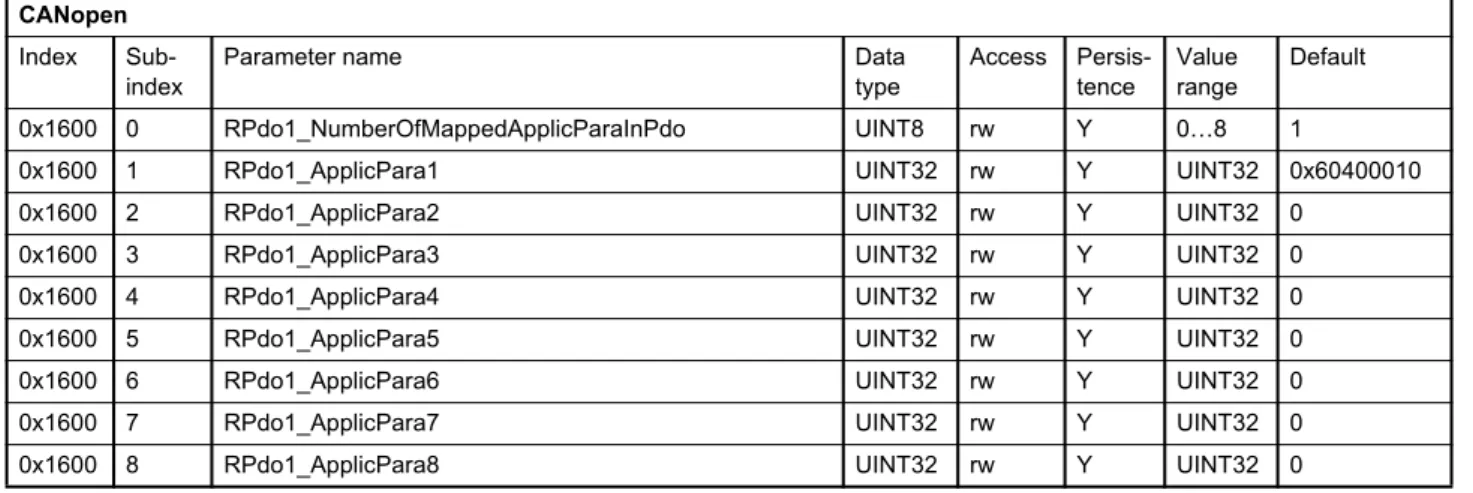
2.8.3.2.1 Object 0x1600: 1st RxPDO mapping ... 23
2.8.3.2.2 Object 0x1601: 2nd RxPDO mapping ... 24
2.8.3.2.3 Object 0x1602: 3rd RxPDO mapping ... 24
2.8.3.2.4 Object 0x1603: 4th RxPDO mapping ... 25
2.8.3.3 RxPDO counter ... 25
2.8.3.3.1 Object 0x3012: RxPDO counter ... 25
2.8.3.4 TxPDO protocol configuration (COB-ID: 0x180, 0x280, 0x380, 0x480) .. 25
2.8.3.4.1 Object 0x1800: 1st TxPDO protocol configuration ... 26
2.8.3.4.2 Object 0x1801: 2nd TxPDO configuration protocol ... 27
2.8.3.4.3 Object 0x1802: 3rd TxPDO protocol configuration ... 27
2.8.3.4.4 Object 0x1803: 4th TxPDO protocol configuration ... 27
2.8.3.5 TxPDO mapping (COB-ID: 0x180, 0x280, 0x380, 0x480)... 28
2.8.3.5.1 Object 0x1A00: 1st TxPDO mapping ... 29
2.8.3.5.2 Object 0x1A01: 2nd TxPDO mapping ... 30
2.8.3.5.3 Object 0x1A02: 3rd TxPDO mapping ... 30
2.8.3.5.4 Object 0x1A03: 4th TxPDO mapping ... 31
2.8.3.6 Object 0x3011: TxPDO trigger ... 31
2.8.4 Service data object (SDO) protocol (COB-ID: 0x580, 0x600) ... 31
2.8.4.1 Object 0x1200: SDO client/server parameter... 31
2.9 Network management state machine (NMT state machine) ... 32
2.9.1 Network management (NMT) protocol (COB-ID: 0x000, 0x700)... 33
2.9.2 Start remote node command (COB-ID:0, CS:1)... 34
2.9.3 Stop remote node command (COB-ID:0, CS:2) ... 34
2.9.4 Enter 'Pre-Operational' command (COB-ID:0, CS:128) ... 34
2.9.5 Reset node command (COB-ID:0, CS:129) ... 34
2.9.6 Reset communication command (COB-ID:0, CS:130) ... 34
2.9.7 Bootup message (COB-ID: 0x700)... 34
2.9.8 Node guarding (COB-ID: 0x700, RTR:1)... 34
2.9.8.1 Object 0x100C: Guard time... 34
2.9.8.2 Object 0x100D: Life time factor ... 35
2.10 Electronic data sheet (EDS) files ... 35
3 Device structure ...37
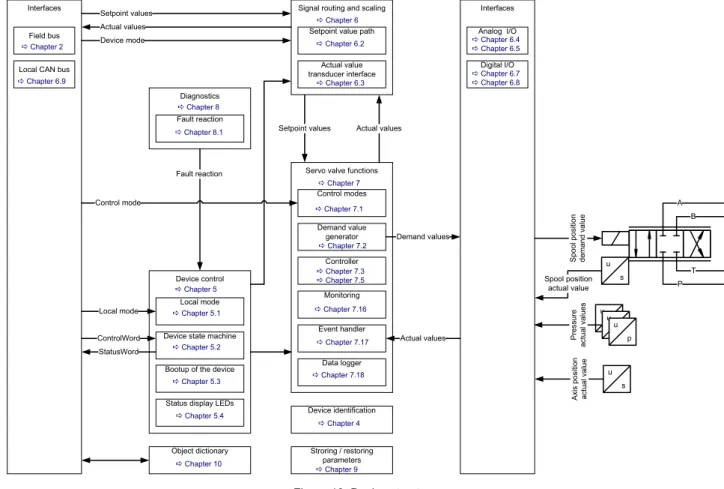
3.1 Overview... 37
3.1.1 Device identification ... 37
3.1.2 Device control... 37
3.1.3 Signal routing and scaling ... 37
3.1.4 Servo valve functions ... 38
3.1.5 Diagnostics... 38
3.1.6 Storing / restoring parameters... 38
3.1.7 Object dictionary... 38
3.2 Device controller structure... 38
4 Device identification ...39
4.1 Objects of the CANopen communication profile defined by CiA 301 ... 39
4.1.1 Object 0x1000: Device Type ... 39
4.1.2 Object 0x1008: Manufacturer device name... 39
4.2 Objects defined by Device Profile Fluid Power ... 40
4.2.1 Object 0x6050: Version ... 40
4.2.2 Object 0x6051: Code number ... 41
4.2.3 Object 0x6052: Serial number... 41
4.2.4 Object 0x6053: Description ... 41
4.2.5 Object 0x6054: Model description ... 41
4.2.6 Object 0x6055: Model URL ... 41
4.2.7 Object 0x6056: Parameter set code... 41
4.2.8 Object 0x6057: Vendor name... 42
4.2.9 Object 0x605F: Capability ... 42
5 Device control ...43
5.1 Local mode... 43
5.1.1 Object 0x604F: Local ... 43
5.1.2 Object 0x6040: Control word... 44
5.1.3 Object 0x4040: Local control word ... 45
5.1.4 Object 0x403F: Local control word default ... 45
5.2 Device state machine (DSM)... 46
5.2.1 DSM states... 47
5.2.2 State transitions... 49
5.2.2.1 DSM state transitions caused by the control word ... 49
5.2.2.2 DSM state transitions caused by the enable signal... 50
5.2.2.3 DSM state transitions caused by internal events ... 50
5.2.2.4 Enable behavior ... 51
5.2.2.4.1 DSM state transitions depending on the enable signal ... 51
5.2.2.4.2 Fault confirmation with the enable signal ... 51
5.2.2.5 Error output pin... 52
5.2.3 Object 0x6041: Status word ... 52
5.2.4 Object 0x1002: Manufacturer Status Register ... 53
5.3 Bootup of the device ... 54
5.3.1 Object 0x200F: Power On Delay... 54
5.4 Status display LEDs ... 54
5.4.1 Module status LED «MS»... 55
5.4.2 Network status LED «NS»... 55
6 Signal routing and scaling ...57
6.1 Signal routing structure... 57
6.2 Setpoint value path ... 58
6.2.1 Object 0x6042: Device mode ... 59
6.2.2 Object 0x4042: Device mode default ... 59
6.2.3 Spool position setpoint value path... 60
6.2.3.1 Object 0x6300: Setpoint ... 60
6.2.3.2 Object 0x3320: Setpoint parameter... 61
6.2.3.3 Object 0x6314: Spl hold setpoint... 61
6.2.4 Pressure setpoint value path... 62
6.2.4.1 Object 0x6380: Setpoint ... 62
6.2.4.2 Object 0x3310: Setpoint parameter... 63
6.2.4.3 Object 0x6394: Prs hold setpoint ... 63
6.2.5 Axis position setpoint value path ... 64
6.2.5.1 Object 0x6600: Setpoint ... 64
6.2.5.2 Object 0x3330: Setpoint parameter... 65
6.2.5.4 16 to 32 bit scaling ... 66
6.2.5.4.1 Object 0x4230: Minimum reference... 66
6.2.5.4.2 Object 0x4231: Maximum reference... 66
6.2.5.4.3 Object 0x5509: Minimum interface ... 66
6.2.5.4.4 Object 0x5510: Maximum interface ... 67
6.2.5.5 Object 0x5700: Trajectory Type ... 67
6.2.5.6 Object 0x585C: Hold setpoint target ... 67
6.2.6 Axis velocity setpoint value path ... 68
6.2.6.1 Object 0x6500: Setpoint ... 68
6.2.6.2 Object 0x5520: Setpoint parameter... 69
6.2.6.3 Object 0x5527: Hold setpoint ... 69
6.2.6.4 16 to 32 bit scaling ... 70
6.2.6.4.1 Object 0x5523: Minimum reference... 70
6.2.6.4.2 Object 0x5524: Maximum reference... 70
6.2.6.4.3 Object 0x5525: Minimum interface ... 70
6.2.6.4.4 Object 0x5526: Maximum interface ... 71
6.2.7 Axis flow setpoint value path ... 71
6.2.7.1 Object 0x5300: Setpoint ... 71
6.2.7.2 Object 0x5202: Setpoint parameter... 72
6.2.7.3 Object 0x5314: Hold setpoint ... 72
6.3 Drive transducer interface ... 73
6.3.1 Object 0x6210: Actual value 1... 74
6.3.2 Object 0x6211: Actual value 2... 74
6.3.3 Object 0x6212: Actual value 3... 74
6.3.4 Object 0x6213: Actual value 4... 75
6.3.5 Object 0x6214: Actual value 5... 75
6.3.6 Object 0x6215: Actual value 6... 75
6.3.7 Object 0x6216: Actual value 7... 75
6.3.8 Object 0x6217: Actual value 8... 75
6.3.9 Transducer interface definition ... 76
6.3.9.1 Object 0x6200: Max interface number ... 76
6.3.9.2 Object 0x6201: Interface number ... 76
6.3.9.3 Object 0x6202: Type ... 77
6.3.9.4 Object 0x6203: Sign ... 77
6.3.9.5 Object 0x6204: Actual value... 78
6.3.9.6 Object 0x4032: Transducer port... 78
6.3.9.7 Object 0x3271: Drive transducer structure... 79
6.3.10 Pressure actual value scaling... 79
6.3.10.1 Object 0x6220: Minimum pressure... 79
6.3.10.2 Object 0x6221: Maximum pressure... 80
6.3.10.3 Object 0x6224: Minimum transducer signal ... 80
6.3.10.4 Object 0x6225: Maximum transducer signal ... 80
6.3.10.5 Object 0x6223: Pressure offset ... 80
6.3.11 Position digital encoder actual value scaling... 81
6.3.11.1 Object 0x6240: Position resolution... 81
6.3.11.2 Object 0x6241: Position offset... 81
6.3.12 Position analog encoder actual value scaling ... 82
6.3.12.1 Object 0x6233: Minimum reference ... 82
6.3.12.2 Object 0x6234: Maximum reference ... 82
6.3.12.3 Object 0x6230: Minimum interface... 83
6.3.14 Parameterization examples... 85
6.3.14.1 Get active transducer interface number and output value... 85
6.3.14.2 Example 1: Enable/disable transducer interface ... 85
6.3.14.3 Example 2: Change sign of the transducer signal... 85
6.3.14.4 Example 3: Adjust transducer interface without scaling ... 86
6.3.14.5 Example 4: Adjust transducer interface with scaling ... 87
6.4 Analog inputs... 88
6.4.1 Analog input 0 ... 89
6.4.1.1 Object 0x3200: Input type ... 89
6.4.1.2 Object 0x3204: Actual value... 89
6.4.2 Analog input 1 ... 89
6.4.2.1 Object 0x3208: Input type ... 89
6.4.2.2 Object 0x320C: Actual value ... 90
6.4.3 Analog input 2 ... 90
6.4.3.1 Object 0x3210: Input type ... 90
6.4.3.2 Object 0x3214: Actual value... 90
6.4.4 Analog input 3 ... 91
6.4.4.1 Object 0x3218: Input type ... 91
6.4.4.2 Object 0x321C: Actual value ... 91
6.4.5 Analog input 4 ... 91
6.4.5.1 Object 0x3220: Input type ... 91
6.4.5.2 Object 0x3224: Actual value... 91
6.4.6 Internal pressure transducer input... 92
6.4.6.1 Object 0x3404: Actual value... 92
6.5 Analog outputs ... 93
6.5.1 Analog output 0 ... 94
6.5.1.1 Object 0x3244: Scaling ... 94
6.5.1.2 Object 0x3245: Actual value... 94
6.5.1.3 Object 0x3240: Parameter ... 94
6.5.1.4 Object 0x3243: Type ... 95
6.5.2 Analog output 1 ... 95
6.5.2.1 Object 0x3265: Scaling ... 95
6.5.2.2 Object 0x3266: Actual value... 95
6.5.2.3 Object 0x3260: Parameter ... 96
6.5.2.4 Object 0x3263: Type ... 96
6.6 Enoder input ... 97
6.6.1 Object 0x5613: Encoder value ... 97
6.6.2 Object 0x5619: Sensor supply enable... 97
6.6.3 Incremental Encoder ... 98
6.6.3.1 Object 0x5614: Referencing velocity... 98
6.6.3.2 Object 0x561A: Referencing force ... 98
6.6.3.3 Object 0x561B: Referencing stop... 98
6.6.3.4 Object 0x5617: Z pulse trigger ... 99
6.6.3.5 Object 0x5611: Z pulse detected... 99
6.6.3.6 Object 0x5618: Z pulse clear... 99
6.6.3.7 Object 0x5610: Z pulse enable... 99
6.6.3.8 Object 0x5612: Z pulse set... 99
6.6.4 SSI encoder... 100
6.6.4.1 Object 0x5620: Master slave... 100
6.6.4.2 Object 0x6243: Bit size... 100
6.6.4.3 Object 0x561F: Bit rate... 100
6.6.4.4 Object 0x3252: SSI Error Count... 101
6.7 Digital inputs... 101
6.8 Digital outputs ... 101
6.8.1 Object 0x5E42: Digital output value ... 102
6.8.2 Object 0x5E41: Digital output type ... 102
6.8.2.1 Object 0x2420: Digital output 1 type ... 103
6.8.3 Object 0x5E44: Digital output monitor... 103
6.9 Local CAN ... 103
6.9.1 Local CAN general configuration... 104
6.9.1.1 Object 0x5B00: Module identifier ... 104
6.9.1.2 Object 0x5B01: Bit rate ... 104
6.9.1.3 Object 0x5B02: Start remote node ... 105
6.9.1.4 Object 0x5B03: TxPDO trigger... 105
6.9.1.5 Object 0x5B14: Termination resistor ... 105
6.9.2 Local CAN process data object (PDO)... 106
6.9.3 Receive process data object (RxPDO) configuration ... 107
6.9.3.1 Object 0x5400: 1st RxPDO configuration... 108
6.9.3.2 Object 0x5401: 2nd RxPDO configuration ... 108
6.9.3.3 Object 0x5402: 3rd RxPDO configuration ... 109
6.9.3.4 Object 0x5403: 4th RxPDO configuration ... 109
6.9.3.5 Receive process data object (RxPDO) mapping... 110
6.9.3.6 Object 0x56007: 1st RxPDO mapping ... 111
6.9.3.7 Object 0x5601: 2nd RxPDO mapping ... 112
6.9.3.8 Object 0x5602: 3rd RxPDO mapping ... 112
6.9.3.9 Object 0x5603: 4th RxPDO mapping ... 113
6.9.4 Transmit process data object (TxPDO) configuration ... 113
6.9.4.1 Object 0x5800: 1st TxPDO configuration ... 114
6.9.4.2 Object 0x5801: 2nd TxPDO configuration... 114
6.9.4.3 Object 0x5802: 3rd TxPDO configuration... 115
6.9.4.4 Object 0x5803: 4th TxPDO configuration... 115
6.9.4.5 Transmit process data object (TxPDO) mapping ... 116
6.9.4.6 Object 0x5A00: 1st TxPDO mapping ... 117
6.9.4.7 Object 0x5A01: 2nd TxPDO mapping ... 118
6.9.4.8 Object 0x5A02: 3rd TxPDO mapping ... 118
6.9.4.9 Object 0x5A03: 4th TxPDO mapping ... 119
6.9.5 Local CAN service data object (SDO) ... 119
6.9.6 Local CAN service data object (SDO) gateway... 120
6.9.6.1 Object 0x5B10: Remote parameter... 121
6.9.6.2 Object 0x5B11: Remote parameter address ... 121
6.9.6.3 Object 0x5B12: Remote node identifier... 122
6.9.6.4 Object 0x5B13: Remote transmission ... 122
6.9.7 Local CAN Synchronization (SYNC) producer protocol emulation... 122
6.10 Free to use parameters ... 123
6.10.1 Object 0x0002: Signed one byte integer ... 123
6.10.2 Object 0x0003: Signed two byte integer... 123
6.10.3 Object 0x0004: Signed four byte integer ... 123
6.10.4 Object 0x0005: Unsigned one byte integer ... 123
6.10.5 Object 0x0006: Unsigned two byte integer... 123
6.10.6 Object 0x0007: Unsigned four byte integer ... 124
6.10.7 Object 0x0008: Float32 ... 124
6.10.8 Object 0x0009: Visible string... 124
6.10.9 Object 0x290B: Signed one byte integer array... 124
7 Servo valve functions ...127
7.1 Control modes ... 128
7.1.1 Object 0x6043: Control mode... 129
7.1.2 Object 0x4043: Control mode default... 129
7.1.3 Spool position control open loop ... 130
7.1.4 Spool position control closed loop... 130
7.1.5 Pressure control open loop ... 131
7.1.6 Pressure control closed loop ... 132
7.1.7 p/Q control closed loop... 133
7.1.8 Axis position control ... 134
7.1.9 Axis velocity control... 135
7.1.10 Axis flow control ... 136
7.1.11 Axis p/flow control ... 137
7.1.12 Sample frequency ... 138
7.1.12.1 Object 0x3030: Basic sample frequency ... 138
7.2 Spool position setpoint conditioning / demand value generator ... 138
7.2.1 Object 0x6310: Demand value ... 138
7.2.2 Object 0x6311: Reference value ... 139
7.2.3 Limit function ... 139
7.2.3.1 Object 0x6320: Upper Limit... 140
7.2.3.2 Object 0x6321: Lower Limit... 140
7.2.4 Scaling... 140
7.2.4.1 Object 0x6322: Factor ... 141
7.2.4.2 Object 0x6323: Offset... 141
7.2.5 Ramp... 142
7.2.5.1 Object 0x6330: Type ... 142
7.2.5.2 One-quadrant ramp (ramp type 1)... 143
7.2.5.2.1 Object 0x6331: Acceleration time... 143
7.2.5.3 Two-quadrant ramp (ramp type 2)... 144
7.2.5.3.1 Object 0x6331: Acceleration time... 144
7.2.5.3.2 Object 0x6334: Deceleration time ... 144
7.2.5.4 Four-quadrant ramp (ramp type 3) ... 145
7.2.5.4.1 Object 0x6332: Acceleration time positive... 145
7.2.5.4.2 Object 0x6333: Acceleration time negative ... 146
7.2.5.4.3 Object 0x6335: Deceleration time positive ... 146
7.2.5.4.4 Object 0x6336: Deceleration time negative... 146
7.2.6 Directional dependent gain... 147
7.2.6.1 Object 0x6340: Type ... 148
7.2.6.2 Object 0x6341: Factor ... 148
7.2.7 Characteristic compensation ... 149
7.2.7.1 Object 0x6346: Type ... 149
7.2.7.2 Look-up table... 150
7.2.7.2.1 Object 0x4347: Look-up table ... 150
7.2.7.2.2 Object 0x4348: Look-up table ... 150
7.2.7.2.3 Object 0x4349: Look-up table ... 150
7.2.7.2.4 Object 0x434A: Look-up table ... 151
7.2.8 Dead band compensation ... 151
7.2.8.1 Object 0x6342: Type ... 152
7.2.8.2 Object 0x6343: A side ... 152
7.2.8.3 Object 0x6344: B side ... 152
7.2.8.4 Object 0x6345: Threshold ... 153
7.2.8.5 Jump function (dead band compensation type 1) ... 153
7.2.8.6 Continuous function (dead band compensation type 2) ... 154
7.2.9 Zero correction ... 155
7.3 Spool position controller ... 156
7.3.1 Single stage servo valve ... 156
7.3.2 Dual stage servo valve ... 156
7.3.3 Spool position / pilot spool position actual value path ... 157
7.3.3.1 Object 0x6301: Actual value... 157
7.3.3.2 Object 0x3301: Actual value pilot ... 157
7.3.3.3 Object 0x3506: Customer Scaling Offset ... 157
7.3.4 Spool position / pilot spool position controller ... 157
7.3.4.1 Object 0x6350: Control deviation ... 158
7.3.4.2 Object 0x241F: Customer Overall Gain ... 158
7.3.5 Main stage spool position actual value path... 158
7.3.5.1 Object 0x3237#1…3: Customer scaling... 158
7.3.5.2 Object 0x3235: Actual value... 158
7.3.6 Main stage transducer selection... 159
7.3.6.1 Object 0x2149: Active transducer interface main stage ... 159
7.3.7 Main stage spool position controller ... 159
7.3.7.1 Object 0x215C: Main stage customer overall gain... 159
7.3.7.2 Object 0x2158: Controller output... 159
7.4 Pressure setpoint conditioning / demand value generator ... 160
7.4.1 Object 0x6390: Demand value ... 160
7.4.2 Object 0x6391: Reference value ... 160
7.4.3 Limit function ... 161
7.4.3.1 Object 0x63A0: Upper Limit ... 161
7.4.3.2 Object 0x63A1: Lower Limit ... 161
7.4.4 Scaling... 162
7.4.4.1 Object 0x63A2: Factor... 162
7.4.4.2 Object 0x63A3: Offset ... 163
7.4.5 Ramp... 163
7.4.5.1 Object 0x63B0: Type... 164
7.4.5.2 One-quadrant ramp (ramp type 1)... 164
7.4.5.2.1 Object 0x63B1: Acceleration time ... 165
7.4.5.3 Two-quadrant ramp (ramp type 2)... 165
7.4.5.3.1 Object 0x63B1: Acceleration time ... 165
7.4.5.3.2 Object 0x63B4: Deceleration time ... 166
7.4.5.4 Four-quadrant ramp (ramp type 3) ... 166
7.4.5.4.1 Object 0x63B2: Acceleration time positive ... 167
7.4.5.4.2 Object 0x63B3: Acceleration time negative... 167
7.4.5.4.3 Object 0x63B5: Deceleration time positive... 167
7.4.5.4.4 Object 0x63B6: Deceleration time negative ... 168
7.5 Pressure controller... 168
7.5.1 Object 0x6381: Actual value... 169
7.5.2 Object 0x63D0: Control deviation... 169
7.5.3 Object 0x2311: Kp T1 output... 169
7.5.4 Object 0x2310: Ki output ... 169
7.5.5 Object 0x2312: Kd output... 169
7.5.6 Object 0x5862: Kd feedback output ... 170
7.5.7 Object 0x2418: Controller output... 170
7.5.8 Active parameter set number ... 171
7.5.8.1 Object 0x2350: Active parameter set number ... 171
7.5.9 Demand pressure ramp function ... 172
7.5.11 Actual value filter ... 175
7.5.11.1 Object 0x23F2: Actual pressure filter cutoff frequency... 175
7.5.11.2 Object 0x23F3: Actual pressure filter order... 175
7.5.12 Proportional first order lag element (PPT1)... 175
7.5.12.1 Object 0x2304[N]: Proportional Gain... 176
7.5.12.2 Object 0x230E[N]: Proportional gain time constant... 176
7.5.13 Integrator element (I)... 176
7.5.13.1 Object 0x2305[N]: Integrator gain ... 176
7.5.13.2 Object 0x2306[N]: Integrator factor ... 177
7.5.13.3 Object 0x2307[N]: Integrator control range ... 177
7.5.13.4 Object 0x231A[N]: Integrator upper output limit ... 177
7.5.13.5 Object 0x231B[N]: Integrator lower output limit... 177
7.5.13.6 Object 0x5861[N]: Integrator proportional part P gain... 177
7.5.14 Integrator preload value ... 178
7.5.14.1 Object 0x586B: Integrator preload mode ... 178
7.5.14.2 Object 0x5869: Integrator preload gain ... 178
7.5.14.3 Object 0x586A: Integrator preload parameter ... 179
7.5.14.4 Object 0x5860: Integrator preload values ... 179
7.5.15 Derivative element (PD) ... 180
7.5.15.1 Object 0x2308[N]: Differentiator gain ... 180
7.5.15.2 Object 0x2309[N]: Differentiator T1... 180
7.5.15.3 Object 0x2324[N]: Spool Position Feed Forward Gain... 180
7.5.16 Feedback derivative element (PD) ... 181
7.5.16.1 Object 0x5863[N]: Differentiator gain 2 ... 181
7.5.16.2 Object 0x5864[N]: Differentiator T1 2... 181
7.5.16.3 Object 0x5858N]: Spool Position Feed Forward Gain_2... 181
7.5.17 Alpha correction ... 182
7.5.18 Signal limitation 1 ... 182
7.5.18.1 Object 0x230A[N]: Upper output limit ... 182
7.5.18.2 Object 0x230B[N]: Lower output limit ... 183
7.5.19 Feed forward ... 183
7.5.19.1 Object 0x5867[N]: Feed forward gain... 183
7.5.19.2 Object 0x5870[N]: Feed forward offset... 183
7.5.19.3 Object 0x5868[N]: Feed forward parameter ... 184
7.5.20 Signal limitation 2 ... 184
7.5.20.1 Object 0x5865[N]: Upper controller output limit... 184
7.5.20.2 Object 0x5866[N]: Lower controller output limit... 185
7.5.21 Automatic parameterization of the pressure controller... 186
7.5.21.1 Object 0x230C[N]: Hydraulic capacity... 187
7.5.21.2 Object 0x231C: Sys Pressure Reference... 187
7.6 Pressure demand signal sign... 187
7.6.1 Object 0x586D: Pressure demand sign mode... 188
7.7 Spool position (Q) / pressure (P) switchover... 188
7.7.1 Object 0x586C[N]: pQ switching mode ... 189
7.7.1.1 Object 0x3300: Demand value pilot ... 189
7.7.2 Minimum criterion in positive direction (switching mode 0) ... 189
7.7.3 Minimum criterion in both directions (switching mode 1)... 190
7.8 Axis position setpoint conditioning / demand value generator... 192
7.8.1 Object 0x6610: Position demand value... 192
7.8.2 Object 0x561E: Velocity demand value... 192
7.8.3 Object 0x5616: Acceleration demand value... 193
7.8.4 Axis position trajectory generator ... 194
7.8.4.1 Object 0x5700: Trajectory type ... 195
7.8.4.2 Object 0x5703: Maximum velocity... 195
7.8.4.3 Object 0x5702: Maximum acceleration ... 195
7.8.5 Axis position demand value filter... 195
7.8.5.1 Object 0x582A: Demand value filter time constant ... 195
7.8.6 Axis position manual movement... 196
7.8.6.1 Object 0x5614: Manual maximum speed ... 196
7.9 Axis position controller ... 196
7.9.1 Object 0x6601: Actual value... 197
7.9.2 Object 0x582B: Demand filter output ... 197
7.9.3 Object 0x6650: Control deviation ... 197
7.9.4 Object 0x552A: Kp output ... 197
7.9.5 Object 0x552A: Kp T1 output ... 197
7.9.6 Object 0x552C: Ki output ... 198
7.9.7 Object 0x552B: Kd output ... 198
7.9.8 Object 0x552E: Velocity feedforward output ... 198
7.9.9 Object 0x552F: Acceleration feedforward output ... 198
7.9.10 Object 0x5530: Velocity feedback output ... 198
7.9.11 Object 0x5531: Acceleration feedback output... 199
7.9.12 Object 0x550F: Controller output ... 199
7.9.13 Sample frequency ... 199
7.9.13.1 Object 0x553F: Sample frequency divider ... 199
7.9.14 Axis position transducer selection ... 200
7.9.14.1 Object 0x6602: Actual value reference ... 200
7.9.15 Axis position synchronisation ... 201
7.9.15.1 Object 0x5829: Synchronisation gain... 201
7.9.15.2 Object 0x5830: Number of axis to synchronize... 201
7.9.16 Proportional element with first order lag element ... 201
7.9.16.1 Object 0x5501: Proportional gain ... 202
7.9.16.2 Object 0x5508: Time constant... 202
7.9.17 Integral element... 202
7.9.17.1 Object 0x5504: Integral gain ... 202
7.9.17.2 Object 0x5511: Integral inner range ... 203
7.9.17.3 Object 0x5505: Integral outer range... 203
7.9.17.4 Object 0x5513: Integral limit... 203
7.9.18 Derivative element... 203
7.9.18.1 Object 0x5502: Differentiator gain... 203
7.9.18.2 Object 0x5503: Differentiator T1 ... 204
7.9.19 Axis velocity feed forward proportional element... 204
7.9.19.1 Object 0x5506: Velocity feed forward proportional gain... 204
7.9.20 Axis acceleration feed forward proportional element ... 204
7.9.20.1 Object 0x5507: Acceleration feed forward proportional gain... 204
7.9.21 State feedback axis velocity and acceleration derivative elements... 205
7.9.21.1 Object 0x550C: Actual value filter time constant... 205
7.9.21.2 Object 0x550B: State feedback axis velocity proportional gain... 205
7.10 Axis velocity setpoint conditioning / demand value generator ... 207
7.10.1 Object 0x5615: Demand value ... 207
7.10.2 Limit function ... 208
7.10.2.1 Object 0x6521: Upper limit ... 208
7.10.2.2 Object 0x6520: Lower limit ... 208
7.10.3 Ramp... 209
7.10.3.1 Object 0x5553: Velocity demand ramp ... 209
7.11 Axis velocity controller ... 210
7.11.1 Axis velocity demand value filter ... 210
7.11.1.1 Object 0x5533: Demand value filter time constant... 210
7.11.1.2 Object 0x553B: Demand value filter output... 210
7.11.2 Axis velocity actual value ... 211
7.11.2.1 Object 0x5542: Actual value reference ... 211
7.11.2.2 Object 0x5548: Actual value filter time constant ... 211
7.11.2.3 Object 0x5552: Actual value filter output... 211
7.11.2.4 Object 0x5550: Actual derivative length ... 212
7.11.2.5 Object 0x5545: Actual value path mode... 212
7.11.2.6 Object 0x5544: Actual value proportional gain... 212
7.11.2.7 Object 0x6501: Axis velocity actual value ... 213
7.11.3 Axis velocity feed forward proportional element... 213
7.11.3.1 Object 0x5547: Velocity feed forward proportional gain... 213
7.11.3.2 Object 0x5546: Velocity feed forward output... 213
7.11.3.3 Object 0x6550: Control deviation ... 213
7.11.4 Proportional element ... 214
7.11.4.1 Object 0x5514: Proportional gain ... 214
7.11.4.2 Object 0x5537: Kp output... 214
7.11.5 Integral element... 214
7.11.5.1 Object 0x5522: Integral gain ... 215
7.11.5.2 Object 0x5517: Integral inner range ... 215
7.11.5.3 Object 0x5516: Integral outer range... 215
7.11.5.4 Object 0x5518: Integral limit... 215
7.11.5.5 Object 0x553C: Ki output ... 215
7.11.6 Acceleration feedback ... 216
7.11.6.1 Feedback axis velocity value filter... 216
7.11.6.2 Object 0x5549: Velocity feedback filter output ... 216
7.11.6.3 Feedback axis velocity derivative element ... 216
7.11.6.4 Object 0x5329: Feedback axis velocity derivative gain... 216
7.11.6.5 Object 0x5539: Acceleration feedback output... 216
7.11.7 Directional depending gain... 217
7.11.7.1 Object 0x5534: Directional depending positive proportional gain ... 217
7.11.7.2 Object 0x5535: Directional depending negative proportional gain ... 217
7.11.8 Signal limitation ... 217
7.11.8.1 Object 0x5519: Controller output... 217
7.11.9 Sample frequency ... 218
7.11.9.1 Object 0x5540: Sample frequency divider... 218
7.12 Axis flow setpoint conditioning / demand value generator... 218
7.13 Axis flow control... 218
7.13.1 Object 0x5213: Deviation value... 219
7.13.2 Object 0x5200: Bernoulli output ... 219
7.13.3 Object 0x520F: Controller output ... 219
7.13.4 Sample frequency ... 219
7.13.5 Axis flow control mode ... 220
7.13.6 Axis flow transducer selection ... 222
7.13.6.1 Object 0x2330: Active transducer interface system ... 222
7.13.6.2 Object 0x5217: Active transducer interface tank... 223
7.13.7 Alpha correction ... 223
7.13.7.1 Object 0x5219: Flow alpha... 223
7.13.7.2 Object 0x5210: Actual value filter time constant ... 223
7.13.8 Axis flow demand value scaling ... 224
7.13.8.1 Object 0x521B: Demand value scaling ... 224
7.13.9 Axis flow actual value selection... 224
7.13.9.1 Object 0x5223: Actual value... 224
7.13.9.2 Object 0x5220: Actual value high pass filter frequency... 224
7.13.9.3 Object 0x5221: Actual value proportional gain... 225
7.13.9.4 Object 0x5222: Actual value parameter ... 225
7.13.10 Feedback axis velocity proportional element ... 225
7.13.10.1 Object 0x5224: Feedback axis velocity proportional gain ... 225
7.13.11 Bernoulli compensation ... 226
7.13.11.1 Object 0x5215: Nominal flow A side... 226
7.13.11.2 Object 0x5216: Nominal flow B side... 226
7.13.11.3 Object 0x521A: Flow beta ... 226
7.13.11.4 Object 0x5203: Nominal supply pressure... 227
7.13.11.5 Object 0x521D: Nominal sensor pressure... 227
7.13.11.6 Object 0x521F: Maximal flow A side ... 227
7.13.11.7 Object 0x521E: Nominal pressure A side... 227
7.14 Axis flow (Flow) / pressure (P) switchover ... 228
7.14.1 Object 0x520E: Flow valve direction ... 228
7.14.2 Continuous signal switching ... 229
7.14.2.1 Object 0x5204: Switching time constant ... 229
7.15 Axis status ... 230
7.15.1 Object 0x561D: Axis status word ... 230
7.15.2 Object 0x561C: Axis status and device status word ... 231
7.15.3 Object 0x570C: Axis position deviation window ... 231
7.15.4 Object 0x570D: Axis velocity actual value window... 231
7.15.5 Object 0x570E: Axis velocity deviation window... 232
7.15.6 Object 0x5710: Pressure deviation window ... 232
7.15.7 Object 0x5711: Pressure actual value limit ... 232
7.16 Monitoring ... 233
7.16.1 Spool position control deviation monitoring... 233
7.16.1.1 Object 0x6351: Type ... 233
7.16.1.2 Object 0x6352: Delay time ... 234
7.16.1.3 Object 0x6354: Upper threshold... 234
7.16.1.4 Object 0x6355: Lower threshold... 234
7.16.2 Pressure control deviation monitoring ... 235
7.16.2.1 Object 0x63D1: Type... 235
7.16.2.2 Object 0x63D2: Delay time... 236
7.16.2.3 Object 0x63D4: Upper threshold ... 236
7.16.2.4 Object 0x63D5: Lower threshold ... 236
7.16.3 Axis position control deviation monitoring ... 237
7.16.3.1 Object 0x6651: Type ... 237
7.16.3.2 Object 0x6652: Delay time ... 238
7.16.5 Failsafe monitoring ... 241
7.16.5.1 Object 0x2421: Upper limit ... 242
7.16.5.2 Object 0x2422: Lower limit ... 242
7.16.6 Pilot/single stage actual spool position monitoring... 242
7.16.7 Main/dual stage actual spool position monitoring... 242
7.16.8 Analog input cable break monitoring ... 243
7.16.8.1 Object 0x3217: Monitoring current ... 243
7.16.8.2 Object 0x3228: Monitoring current ... 244
7.16.8.3 Object 0x3227: Monitoring current ... 244
7.16.8.4 Object 0x3250: Lower current border... 245
7.16.8.5 Object 0x3251: Analog input monitoring time... 245
7.16.9 Sensor power supply monitoring ... 245
7.16.10 Hardware monitoring ... 245
7.16.10.1 Object 0x2803: CPU supply voltage... 245
7.16.10.2 Object 0x2804: Power supply voltage ... 246
7.16.10.3 Object 0x2805: PCB temperature ... 246
7.16.10.4 Object 0x280D: Operating time ... 246
7.17 Event handler... 247
7.17.1 Event expressions ... 247
7.17.1.1 Object 0x2901: Event expression 1... 249
7.17.1.2 Object 0x2902: Event expression 2... 249
7.17.1.3 Object 0x2903: Event expression 3... 249
7.17.1.4 Object 0x2904: Event expression 4... 249
7.17.1.5 Object 0x2905: Event expression 5... 249
7.17.1.6 Object 0x2906: Event expression 6... 249
7.17.1.7 Object 0x2907: Event expression 7... 250
7.17.1.8 Object 0x2908: Event expression 8... 250
7.17.1.9 Object 0x2909: Event enable ... 250
7.17.2 Event handler examples... 251
7.18 Data logger... 251
7.18.1 Data logger state machine ... 252
7.18.1.1 Object 0x3180: Control... 253
7.18.1.2 Object 0x3181: Status ... 253
7.18.2 Channel settings... 254
7.18.2.1 Object 0x3185: Channel parameter ... 254
7.18.2.2 Object 0x3184: Enable channel ... 254
7.18.3 Sample frequency ... 255
7.18.3.1 Object 0x3182: Divider ... 255
7.18.4 Trigger settings... 255
7.18.4.1 Object 0x3189: Trigger parameter ... 256
7.18.4.2 Object 0x3188: Trigger type ... 256
7.18.4.3 Object 0x318C: Trigger level or bitmask ... 256
7.18.4.4 Object 0x318A: Trigger coupling ... 257
7.18.4.5 Object 0x318B: Trigger slope... 257
7.18.4.6 Object 0x318D: Trigger position... 257
7.18.5 Data memory... 258
7.18.5.1 Object 0x3186: Memory ... 259
7.18.5.2 Object 0x3187: Sample start offset ... 259
7.19 Function generator... 260
7.19.1 Function generator output signal shapes ... 260
7.19.1.1 Rectangular output signal (type 1) ... 260
7.19.1.2 Triangle output signal (type 2)... 261
7.19.1.3 Sawtooth signal (type 3)... 261
7.19.1.4 Trapezoid signal (type 4)... 261
7.19.1.5 Sine signal (type 5)... 262
7.19.1.6 Object 0x3100: Type ... 262
7.19.1.7 Object 0x3104: Magnitude ... 262
7.19.1.8 Object 0x3105: Offset... 262
7.19.1.9 Object 0x3107: Sign ... 263
7.19.2 Function generator output signal frequency ... 263
7.19.2.1 Object 0x3103: Frequency ... 263
7.19.2.2 Object 0x3108: Frequency prefix ... 263
7.19.3 Function generator output signals ... 264
7.19.3.1 Object 0x3101: Output signal ... 264
7.19.3.2 Object 0x3102: Square output (Trigger signal) ... 264
8 Diagnostics...265
8.1 Fault reaction ... 265
8.1.1 Fault reaction flow chart ... 266
8.1.2 Possible fault codes ... 267
8.1.3 Fault reaction type... 270
8.1.3.1 Object 0x2830: Fault reaction type... 270
8.1.4 Error codes depending on fault codes... 271
8.1.5 Fault status... 273
8.1.5.1 Object 0x2831: Fault status... 273
8.1.5.2 Object 0x2834: Fault retain status... 273
8.1.6 Error register ... 274
8.1.6.1 Object 0x1001: Error register ... 274
8.1.7 Last eight fault codes and error codes ... 274
8.1.7.1 Object 0x1003: Predefined error field... 275
8.1.8 Last eight error message descriptions ... 276
8.1.8.1 Object 0x2832: Fault reaction description ... 276
8.1.8.2 Object 0x2833: Fault history number ... 276
8.1.9 Emergency message... 277
8.1.10 Fault disappears... 277
8.1.11 Fault acknowledgement ... 278
8.2 Internal errors ... 278
8.2.1 Object 0x2822: Internal error code... 278
8.2.2 Object 0x2823: Internal error time... 278
8.3 Abort SDO Transfer Protocol ... 279
9 Storing / restoring parameters...281
9.1 Storing parameters... 282
9.1.1 Object 0x1010: Store parameters ... 282
9.2 Restoring factory parameters ... 283
List of tables
Table 1: Abbreviations... 6
Table 2: CANopen slave reference model... 10
Table 3: Field bus independent attributes ... 12
Table 4: Unit representation ... 13
Table 5: Prefix representation ... 13
Table 6: Structure of the CANopen object dictionary (OD)... 13
Table 7: CANopen bit rates ... 14
Table 8: CANopen bit rates ... 16
Table 9: CANopen communication objects ... 17
Table 10: Possible values of parameter <CobIdSyncMessage> (0x1005)... 18
Table 11: Possible values of parameter <CobIdEmergencyMessage> (0x1014) ... 18
Table 12: Object 0x1400: 1st RxPDO configuration... 20
Table 13: Possible values of parameter <RPdo1_CobIdUsedByPdo> (0x1400, sub-index 1)... 20
Table 14: Possible values of parameter <RPdo1_TransmissionType> (0x1400, sub-index 2)... 20
Table 15: Object 0x1600: 1st RxPDO mapping... 23
Table 16: Value description of mapping parameter <RPdo1_ApplicPara1>…<RPdo1_ApplicPara8> ... 23
Table 17: Object 0x1800: 1st TxPDO configuration ... 26
Table 18: Possible values of parameter <TPdo1_CobIdUsedByPdo> (0x1800 sub-index 1) ... 26
Table 19: Possible values of parameter <TPdo1_TransmissionType> (0x1400, sub-index 2) ... 26
Table 20: Object 0x1600: 1st TxPDO mapping ... 29
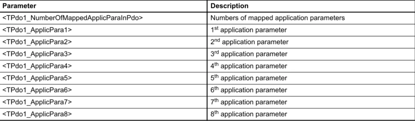
Table 21: Possible values of parameter <TPdo1_ApplicPara1>…<TPdo1_ApplicPara8> ... 29
Table 22: Object 0x1200: SDO client/server parameter... 31
Table 23: NMT state transitions... 33
Table 24: NMT states ... 33
Table 25: Possible values of parameter <DeviceType> (0x1000)... 39
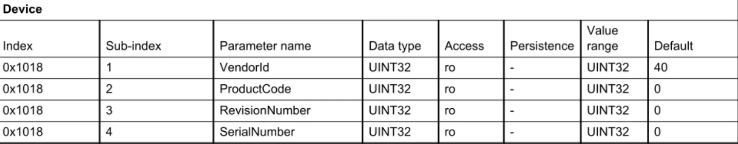
Table 26: Possible values of parameter Identity object (0x1018)... 40
Table 27: Possible values of parameter <Capability> (0x605F)... 42
Table 28: Bit values of parameter <Capability> (0x605F) ... 42
Table 29: Possible values of parameter <Local> (0x604F) ... 43
Table 30: Possible values of parameter <ControlWord> (0x6040)... 44
Table 31: Possible values of parameter <StatusWord> (0x6041) ... 52
Table 32: Possible values of parameter <DeviceMode> (0x6042)... 59
Table 33: Possible values of parameter <SplSetpointParameter> (0x3320)... 61
Table 34: Possible values of parameter <PrsSetpointParameter> (0x3310) ... 63
Table 38: Possible values of parameter <VelSetpointParameter> (0x5520)... 69
Table 39: Possible values of parameter <FlwSetpointParameter> (0x5202) ... 72
Table 40: Possible values of parameter <InterfaceNumber> (0x6201) ... 76
Table 41: Possible values of parameter <Type> (0x6202)... 77
Table 42: Possible values of parameter <Sign> (0x6203)... 77
Table 43: Possible values of parameter <TransducerPort> (0x4032) ... 78
Table 44: Possible values of parameter <InputType> (0x3200)... 89
Table 45: Possible values of parameter <InputType> (0x3210)... 90
Table 46: Possible values of parameter <Parameter> (0x3240) ... 94
Table 47: Possible values of parameter <Type> (0x3243)... 95
Table 48: Possible values of parameter <Parameter> (0x3260) ... 96
Table 49: Possible values of parameter <Type> (0x3263)... 96
Table 50: Possible values of parameter <SensorSupplyEnable> (0x5619) ... 97
Table 51: Possible values of parameter <MasterSlave> (0x5620)... 100
Table 52: Possible values of parameter <BitRate> (0x561F)... 100
Table 53: Possible values of parameter <DigitalOutputType> (0x5E41)... 102
Table 54: Receive PDOs and corresponding COB-IDs... 107
Table 55: Parameters of 1st RxPDO configuration object (0x5400)... 108
Table 56: Possible values of parameter <LocalRPdo1_CobIdUsedByPdo> (0x5400)... 108
Table 57: Possible values of parameter <LocalRPdo1_TransmissionType> (0x5400)... 108
Table 58: Parameters of 1st RxPDO mapping object (0x5600) ... 111
Table 59: Value description of mapping parameter <LocalRPdo1_ApplicPara1…8> ... 111
Table 60: Transmit PDOs and corresponding COB-IDs... 113
Table 61: Parameters of 1st TxPDO configuration object (0x5800) ... 114
Table 62: Possible values of parameter <LocalTPdo1_CobIdUsedByPdo> (0x5800) ... 114
Table 63: Possible values of parameter <LocalTPdo1_TrasnmissionType> (0x5800) ... 114
Table 64: Parameters of 1st TxPDO mapping object (0x5A00) ... 117
Table 65: Possible values of parameter <LocalTPdo1_ApplicPara1…8>... 117
Table 66: Possible values of parameter <LocalCANRemoteParameter> (0x5B10)... 121
Table 67: Possible values of parameter <LocalCANRemoteParameterAdress> (0x5B11)... 121
Table 68: Possible values of parameter <LocalCANRemoteTransmission> (0x5B13) ... 122
Table 69: Control mode values... 128
Table 70: Possible values of parameter <ControlMode> (0x6043) ... 129
Table 77: Possible values of parameter <DeadbandCompensation_Type> (0x6342) ... 152
Table 78: Data structure of the slope factor ... 162
Table 79: Possible values of parameter <Type> (0x63B0) ... 164
Table 80: Pressure controller objects contained in a parameter set ... 171
Table 81: Possible values of parameter <IntegratorPreloadMode> (0x586B)... 178
Table 82: Behavior of preload output ... 179
Table 83: Parameters used in a linear plant model ... 186
Table 84: Possible values of parameter <PressureDemandSignMode> (0x586D) ... 188
Table 85: Possible values of parameter <pQSwitchingMode> (0x586C) ... 189
Table 86: Possible values of parameter <VelActualPathMode> (0x5545) ... 212
Table 87: Possible values of parameter <FlwControlMode> (0x5205)... 221
Table 88: Possible values of parameter <FlwActualValueParameter> (0x5222) ... 225
Table 89: Possible values of parameter <AxisStatusWord> (0x561D)... 230
Table 90: Possible values of parameter <AxisStatusAndDeviceStatusWord> (0x561C) ... 231
Table 91: Possible values of parameter <Type> (0x6351)... 233
Table 92: Possible values of parameter <Type> (0x63D1) ... 235
Table 93: Possible values of parameter <Type> (0x6651)... 237
Table 94: Possible values of parameter <Type> (0x6651)... 239
Table 95: Cable break monitoring features ... 243
Table 96: Possible fault codes... 243
Table 97: Fault codes ... 245
Table 98: Fault codes ... 246
Table 99: Fault codes ... 246
Table 100: States of the data logger state machine ... 252
Table 101: Transitions of the data logger state machine... 253
Table 102: Possible values of parameter <Control> (0x3180) ... 253
Table 103: Possible values of parameter <Status> (0x3181)... 253
Table 104: Possible values of parameter <EnableParameter> (0x3184)... 254
Table 105: Possible values of parameter <Divider> (0x3182)... 255
Table 106: Possible values of parameter <TriggerType> (0x3188) ... 256
Table 107: Possible values of parameter <TriggerCoupling> (0x318A)... 257
Table 108: Possible values of parameter <TriggerSlope> (0x318B)... 257
Table 109: Possible values of parameter <TriggerPosition> (0x318D) ... 257
Table 110: Possible values of parameter <Type> (0x3100)... 262
Table 111: Possible values of parameter <FunctionGenFrequencyPrefix> (0x3108) ... 263
Table 112: Possible fault codes... 267
Table 116: Possible values of parameter <PreDefinedErrorField> (0x1003) ... 275
Table 117: SDO Abort Codes... 279
Table 118: Behavior of saveable and volatile parameters... 281
Table 119: Possible values of parameter 0x1010 ... 282
Table 120: Possible values of parameter 0x1011 ... 283
Table 121: State changes needed to activate the restored values... 283
List of figures
Figure 1: Structure of a warning notice... 3
Figure 2: Servo valve position and stage names... 6
Figure 3: CANopen slave reference model... 10
Figure 4: CAN protocol ... 14
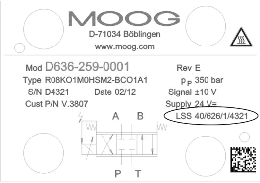
Figure 5: Name plate of the device with identification object address ... 15
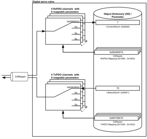
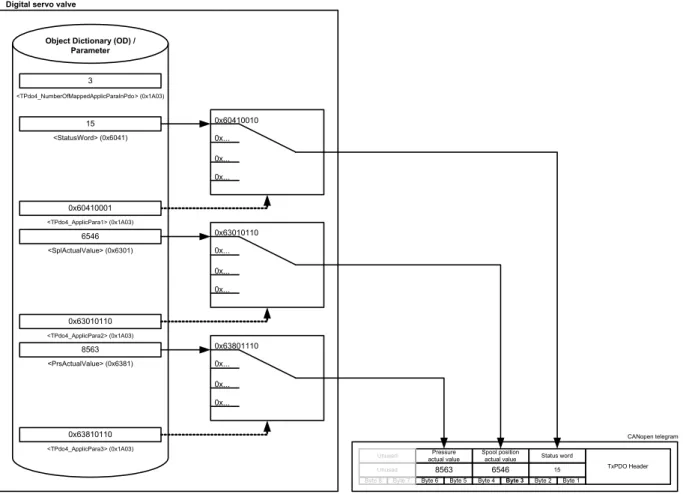
Figure 6: Process data object (PDO) mapping ... 19
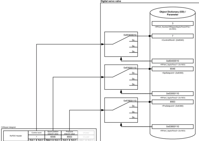
Figure 7: Receive process data object (RxPDO) mapping ... 22
Figure 8: Transmit process data object (TxPDO) mapping ... 28
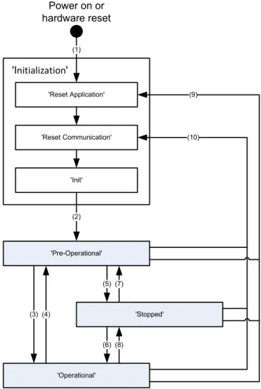
Figure 9: CANopen network state machine (CSM)... 32
Figure 10: Device structure... 37
Figure 11: Device controller structure... 38
Figure 12: Name plate of the device with identification object address ... 40
Figure 13: Local mode ... 43
Figure 14: Device state machine ... 46
Figure 15: Status display LEDs ... 54
Figure 16: Signal routing... 57
Figure 17: Spool position setpoint value path... 60
Figure 18: Pressure setpoint value path ... 62
Figure 19: Axis position setpoint value path ... 64
Figure 20: Axis position setpoint value path - 16 to 32 bit scaling ... 66
Figure 21: Axis velocity setpoint value path... 68
Figure 22: Axis velocity setpoint value path - 16 to 32 bit scaling ... 70
Figure 23: Axis flow setpoint value path ... 71
Figure 24: Drive actual value path ... 73
Figure 25: Pressure actual value scaling... 79
Figure 26: Position digital encoder actual value scaling ... 81
Figure 27: Position analog encoder actual value scaling... 82
Figure 28: General input scaling... 83
Figure 29: Analog inputs... 88
Figure 30: Analog outputs... 93
Figure 31: Analog output scaling ... 93
Figure 32: Encoder input ... 97
Figure 33: Digital inputs ... 101
Figure 34: Digital outputs in the default configuration... 101
Figure 38: Transmit process data object (TxPDO) mapping ... 116 Figure 39: Local CAN service data object (SDO) gateway... 120 Figure 40: Servo valve controller and command signal conditioning... 127 Figure 41: Spool position control open loop ... 130 Figure 42: Spool position control closed loop ... 130 Figure 43: Pressure control open loop... 131 Figure 44: Pressure control closed loop ... 132 Figure 45: p/Q control closed loop... 133 Figure 46: Axis position control... 134 Figure 47: Axis velocity control ... 135 Figure 48: Axis flow control... 136 Figure 49: Axis p/flow control... 137 Figure 50: Spool position demand value generator ... 138 Figure 51: Limit function ... 139 Figure 52: Scaling function ... 140 Figure 53: Ramp function ... 142 Figure 54: Ramp type 1 ... 143 Figure 55: Ramp type 2 ... 144 Figure 56: Ramp type 3 ... 145 Figure 57: Directional depending gain ... 147 Figure 58: Characteristic compensation ... 149 Figure 59: Dead band compensation... 151 Figure 60: Dead band compensation type 1... 153 Figure 61: Dead band compensation type 2... 154 Figure 62: Zero correction ... 155 Figure 63: Single stage servo valve... 156 Figure 64: Dual stage servo valve ... 156 Figure 65: Pressure demand value generator ... 160 Figure 66: Limit function ... 161 Figure 67: Scaling function ... 162 Figure 68: Ramp function ... 163 Figure 69: Ramp type 1 ... 164 Figure 70: Ramp type 2 ... 165 Figure 71: Ramp type 3 ... 166
Figure 77: Integrator element (I) ... 176 Figure 78: Integrator preload value... 178 Figure 79: Proportional derivative element 1 (PD)... 180 Figure 80: Proportional derivative element 2 (PD)... 181 Figure 81: Alpha correction... 182 Figure 82: Signal limitation 1 ... 182 Figure 83: Feed forward ... 183 Figure 84: Signal limitation 2 ... 184 Figure 85: Parameterization of the pressure controller... 186 Figure 86: Pressure demand signal sign ... 187 Figure 87: Spool position (Q) / pressure (P) switchover ... 188 Figure 88: State machine used to switch between spool position control and pressure control... 189 Figure 89: State machine used to switch between spool position control and pressure control... 190 Figure 90: State machine used to switch between spool position control and pressure control... 191 Figure 91: Axis position setpoint conditioning / demand value generator... 192 Figure 92: Axis position trajectory generator ... 194 Figure 93: Axis position derivation... 194 Figure 94: Axis position demand value filter ... 195 Figure 95: Axis position controller... 196 Figure 96: Axis position transducer selection ... 200 Figure 97: Axis position synchronisation ... 201 Figure 98: Proportional element with first order lag element ... 201 Figure 99: Integral element... 202 Figure 100: Derivative element... 203 Figure 101: Axis velocity feed forward proportional element ... 204 Figure 102: Axis acceleration feed forward proportional element... 204 Figure 103: State feedback axis velocity and acceleration derivative element... 205 Figure 104: State feedback axis velocity proportional gain ... 205 Figure 105: State feedback axis acceleration proportional gain ... 206 Figure 106: Directional depending gain ... 206 Figure 107: Signal limitation ... 207 Figure 108: Axis velocity setpoint conditioning / demand value generator ... 207 Figure 109: Limit function ... 208 Figure 110: Ramp function ... 209 Figure 111: Velocity demand ramp... 209 Figure 112: Axis velocity controller ... 210 Figure 113: Axis velocity demand value filter ... 210
Figure 116: Axis velocity feed forward proportional element ... 213 Figure 117: Proportional element ... 214 Figure 118: Integral element... 214 Figure 119: Feedback axis velocity value filter ... 216 Figure 120: Feedback axis velocity derivative element ... 216 Figure 121: Directional depending gain ... 217 Figure 122: Signal limitation ... 217 Figure 123: Axis flow setpoint conditioning / demand value generator... 218 Figure 124: Axis flow control... 218 Figure 125: Axis flow control mode... 220 Figure 126: Axis flow transducer selection ... 222 Figure 127: Alpha correction... 223 Figure 128: Axis flow demand value scaling... 224 Figure 129: Axis flow actual value selection ... 224 Figure 130: Feedback axis velocity proportional element... 225 Figure 131: Bernoulli compensator... 226 Figure 132: Maximal flow A side... 227 Figure 133: Axis flow / pressure switchover ... 228 Figure 134: Continuous signal switching ... 229 Figure 135: Spool position control deviation monitoring ... 233 Figure 136: Pressure control deviation monitoring ... 235 Figure 137: Axis position control deviation monitoring ... 237 Figure 138: Axis velocity control deviation monitoring... 239 Figure 139: Failsafe monitoring ... 241 Figure 140: 4…20 mA analog input signal monitoring... 244 Figure 141: Data logger state machine... 252 Figure 142: Data memory organization ... 258 Figure 143: Data memory - mixed channel data... 258 Figure 144: Data memory - one channel with INT8 parameter... 259 Figure 145: Data memory - four channels with INT32 parameters... 259 Figure 146: Rectangular output signal (type 1)... 260 Figure 147: Triangle output signal (type 2) ... 261 Figure 148: Saw signal (type 3) ... 261 Figure 149: Trapezoid signal (type 4) ... 261
1 General information
1.1 About this manual
This document describes the CANopen field bus interface of the Moog servo valves.
It describes and explains the general structure of the CANopen field bus interface and in a second part the de-vice specific profile for hydraulic valves will be explained.
All parameters follow the common CANopen communication profile CiA 301 / CiA 301-1 / CiA 305 and the de-vice specific CANopen profile "Dede-vice profile fluid power technology proportional valves and hydrostatic trans-missions", CiA 408 released by the CAN in Automation (CiA) organisation.
This manual is part of the set of documentation available for the servo valve.
Chapter "1.4 Further documentation for the servo valve", page 4
This manual was prepared with great care and the contents reflect the author’s best knowledge. However, the possibility of error remains and improvements are possible.
Please feel free to submit any comments regarding errors or possibly incomplete information to Moog.
1.1.1 Reservation of changes and validity
The information contained in this manual is valid at the time of this version's release. See footer for version number and release date of this manual.
We reserve the right to make changes to this manual at any time without specified reasons.
1.1.2 Completeness
This manual is complete only when used in conjunction with the product related hardware and software docu-mentation required for the relevant application.
1.1.3 Place of storage
This manual and all other associated documentation for hardware and software must always be kept in a loca-tion where they will be readily accessible and close to the servo valve or the equipment in which it is installed.
1.1.4 Warranty and liability
This manual only describes the functionality and influence of the parameters. The described software func-tionality can be used in various servo valve models which can be implemented in a vast range of applications. Hence it is not possible to assume liability for the influence of the parameters. Please refer to the safety in-structions and remarks in the related operating inin-structions.
This document is not a replacement for the CANopen standards as listed in the references.
1.1.5 Typographical conventions
DANGER
Identifies safety instructions that are intended to warn of an immediate and impending danger to life and limb.
Failure to observe these safety instructions will inevitably lead to death, serious personal injury (disable-ment)!
WARNING
Identifies safety instructions that are intended to warn of potential danger to life and limb.
Failure to observe these safety instructions might lead to death, serious personal injury (disablement)!
CAUTION
Identifies safety instructions that are intended to warn of slight personal injury. Failure to observe these safety instructions might lead to slight personal injury.
NOTICE
Failure to observe this safety notice can result in property damage! Identifies important information
• / - Identifies listings
Identifies references to another chapter, page, table or figure in this manual
blue text Identifies a hyperlink within the PDF file
1., 2., … Identifies steps in a procedure that should be performed in consecutive order 'STATE' Identifies states of a state machine
«MS» Identifies LEDs of the servo valve (for example, «MS») < > Identifies a parameter name
1.2 Structure of warning notices
The warning notices in this user manual have the following structure:
Figure 1: Structure of a warning notice Legend
1.3 Selection and qualification of personnel
Only qualified users may work with the servo valve. Qualified users are properly trained experts with the re-quired knowledge and experience. In particular, these experts must have the authorization to bring into oper-ation systems and power circuits in accordance with safety engineering standards. They must be familiar with safety concepts common in automation.
DANGER
Moving machine parts!
Entrapment hazard!
Do not enter danger zone!
1 2 3 4 5 1 Warning symbol 2 Signal word
3 Type and source of hazard
4 Possible consequences if a potential hazard 5 Hazard prevention measures
1.4 Further documentation for the servo valve
This manual is part of the complete set of documentation for the servo valve, which includes the following doc-uments:
Visit http://www.moog.com/industrial/literature to download the desired documents.
User manuals
B97072-670 Product Installation Instruction
Servo- Proportional Valves and Servovalves D67x Series
B97072-636 User Manual
Mounting and Installation Notes D636/7/8/9 Series - Servovalves B97072-630 User Manual
Mounting and Installation Notes, Servovalves D630 Series B97072-941 Mounting and Installation Notes,
pQ-Proportional Valves D941/2/3/4 Series
CA63420-001 User Manual Electrical Interfaces
Description of the electrical interfaces for the series D636, D637, D638, D639, D67x, D930, D94x and the RKP-D
B95872-001 Operating Instructions D636 and D637/D638 Series Direct-Operated Servovalves C43357-001-en + de Operating Instructions
D941 Series
Two-State pQ-Proportional Valves with Integrated Digital Electronics and CAN Bus Interface CA45707-002 Betriebsanleitung Servoventile
Serie D636/D638
Direktbetätigte Servoventile CA61892-001 User Manual
Direct Drive Servovalves with integrated Digital Electronics and Fieldbus, Size NG10 D637-R/D639-R Series
CA75181-002 Benutzerinformation
Vorgesteuerte Proportionalventile, Größe NG10 - NG32 Baureihe D67x nach ISO 4401
Explosion proof valves
CDS29587-en User Manual for Direct Driven Servovalves with Integrated Digital Electronics (explosion proof) Series D636K and D638K, Size 03
CDS29577-en User Manual for Direct Operated Servo- and Proportional Valves with Integrated Digital Electronics (explosion proof)
Series D637K und FD639K, Size 05
CDS29588-en User Manual for Pilot operated Proportional Valves with Integrated Digital Electronics (explosion proof) D67xK Series
CDS29589-en User Manual for Pilot Operated Proportional valves with Integrated Digital Electronics (explosion proof) Series D94xK
Miscellaneous documents
CA58437-001 Technical Note TN353
Protective Grounding and Electrical Shielding of Valves CA48851-001 Technical Note TN494
Maximum Permissible Length of Electric Cables for Valves with Integrated Electronics
CDL28319-en Catalog - D671-D672-D673-D674-D675 Series Drive Servo-Proportional Valves with Integrated Digital Electronics and CAN bus Interface
1.5 References
In this chapter you will find information about standards for CANopen, CANopen and the used device profile. In the following table you see all relevant organizations for standardization.
1.5.1 CAN field bus
The CANopen field bus interface provides a connection to the servo valves using standard CAN frames ac-cording to ISO 11898-1…3 and ISO 11898-5.
1.5.2 Device Profile
1.6 Definitions
1.6.1 Internal resolution (iR)
The internal resolution is 16384 (0x4000) at 100 % and –16384 (0xC000) at –100 % of the value range. ISO International Organization for Standardization
1, ch. de la Voie-Creuse, Case postale 56 CH-1211 Geneva 20
http://www.iso.org
IEC International Engineering Consortium 233 S. Wacker Drive, Suite 8400 Chicago, IL 60606-6338 USA
http://www.iec.org
CiA CAN in Automation
Kontumazgarten 3 DE-90429 Nuremberg
http://www.can-cia.org
VDMA Verband Deutscher Maschinen- und Anlagenbau e.V. Lyoner Strasse 18
60528 Frankfurt/Main
http://www.vdma.org
CiA 301 CANopen application layer and communication profile CiA 303-1 Cabling and connector pin assignment
CiA 305 Layer setting services (LSS) and protocols
ISO 11898-1 Road vehicles -- Controller area network (CAN) -- Part 1: Data link layer and physical ISO 11898-2 Road vehicles -- Controller area network (CAN) -- Part 2: High-speed medium access unit ISO 11898-3 Road vehicles -- Controller area network (CAN) -- Part 3: Low-speed, fault-tolerant,
medium-de-pendent interface
ISO 11898-5 Road vehicles -- Controller area network (CAN) -- Part 5: High-speed medium access unit with low-power mode
VDMA Profile Fluid Power Device profile for Proportional Valves and Hydrostatic Transmissions VDMA Profile Fluid Power Technology Version 1.5
CiA 408 or Device Profile Fluid Power
CiA 408 Device profile for fluid power technology proportional valves and hydrostatic transmis-sions, Version 1.5e
1.6.3 Servo valve position and stage names
Figure 2: Servo valve position and stage names
1.7 Abbreviations
T P B A X Y T P B A Spool position Pilot positionMain stage position
s u s u s u Spool position Pilot Main stage Main stage
Dual stage servo valve Single stage servo valve
Abbreviation Explanation
AC Alternating Current CAN Controller Area Network
CANopen ISO/OSI Layer 7 protocol, specified by CAN in Automation (CiA) CiA CAN in Automation
COB-ID Communication Object Identifier DC Direct Current
DCV Moog Digital Control Valve DSM Device State Machine DSP Digital Signal Processor DSV Device specific value
EDS Electronics Datasheet, containing a description of the CANopen object dictionary EEPROM Electrically erasable programmable read-only memory
iR Internal resolution defined by CiA 408 ISO International Engineering Consortium LED Light Emitting Diode
LVDT Linear Variable Differential Transformer used to measure the valves spool position NMT Network management according CANopen
NS Network Status OD Object Dictionary
OSI Open Systems Interconnection P Proportional gain element PD Proportional derivative element PDO Process Data Object
PE Protective earth / Electrical grounding PPT1 Proportional first order lag element
1.8 Trademarks
Moog and Moog Authentic Repair® are registered trademarks of Moog Inc. and its subsidiaries. RxPDO Receive Process Data Object
RxPDO remote Receive Process Data Object remote RxSDO Receive Service Data Object SDO Service Data Object
TR State transmission of the valve application state machine TxPDO Transmit Process Data Object
TxPDO remote Transmit Process Data Object remote TxSDO Transmit Service Data Object
URL Uniform Resource Locator / Internet address VDMA Verband Deutscher Maschinen- und Anlagenbau e.V.
wo Write only
Xn Physical connector n for electrical connection
Abbreviation Explanation
Table 1: Abbreviations (part 2 of 2)
All the product and company names mentioned in this document are possibly proprietary names or trademarks of the respective manufacturers. The use of these names by third parties for their own purposes may infringe the rights of the manufacturers.
It cannot be inferred from the absence of the ® or ™ symbol that the designation is a free brand name.
2
Access over CANopen
2.1 Introduction
CANopen is a communication protocol and device profile specification for embedded systems used in auto-mation. In terms of the Open Systems Interconnection (OSI) model, CANopen implements the above layers and the network layer. The CANopen standard consists of an addressing scheme, several communication protocols and an application layer defined by specific device profiles. The communication protocols have sup-port for network management, device monitoring and communication between nodes. The lower level protocol implementing the data link and physical layers is usually Controller Area Network (CAN). The basic CANopen application and communication profiles are given in the CiA 301 specification released by CAN in Automation (CiA). The device profiles for different devices are built on top of this basic profile.
2.2 Device profiles
The German Engineering Federation (VDMA), together with the manufacturers of hydraulic devices, have de-veloped the "profile for fluid power technology". This profile defines common functionality and parameters for the communication of hydraulic components via field bus in a standardized format across manufacturers. This profile is implemented in all Moog servo valves with field bus interface. The CiA organization transformed the bus-independent device profile from the VDMA to the CANopen specific device profile CiA 408 "Device Profile Fluid Power Technology - proportional valves and hydrostatic transmissions". The device profiles describe the application parameters and the functional behavior of the devices including the device class-specific state ma-chines. For many device classes, field bus technology already offers reliable device profiles for example for generic I/O-modules (CiA 401), drives and motion control (CiA 402) or for fluid power technology, proportional valves and hydrostatic transmissions (CiA 408). Users should be familiar with the associated profile.
2.3 CANopen slave reference model
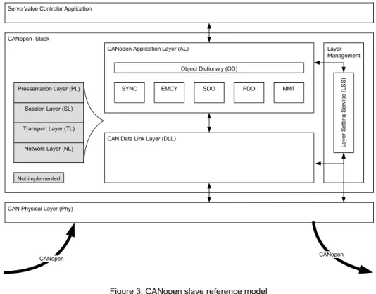
The architecture of the CANopen stack with Physical Layer (Phy), Data Link Layer (DL) and Application Layer (AL) was taken from the ISO Reference Model (ISO/IEC standard 7498-1:1994). Layers three to six of this 7-layer reference model were not implemented, as these layers are intended for exchanging and sending tele-grams. In a real-time field bus system, such functionalities are not required. The CANopen communication concept can be described similar to the ISO/OSI reference model.
Figure 3: CANopen slave reference model
CANopen is based on the CAN data link layer and high-speed transceiver as specified in ISO 11898. CANopen specifies in CiA 303-1 the bit-timing and recommends connectors and their pin-assignments. CANopen represents a standardized application layer and communication profile as defined in CiA 301. The CiA 305 specifies the layer setting services (LSS). These protocols are used to inquire or to change the settings of the physical layer, data link layer and application layer on a device.
Object Dictionary (OD)
SDO CANopen Application Layer (AL)
CAN Data Link Layer (DLL)
Layer Management Lay er S e tti ng Ser vi ce ( LSS)
Servo Valve Controler Application
CAN Physical Layer (Phy) Network Layer (NL) Transport Layer (TL) Session Layer (SL) Pressentation Layer (PL) CANopen Stack Not implemented CANopen CANopen PDO EMCY SYNC NMT Layer Description References CAN / CANopen
Layer 7 Application layer CiA 301 (CANopen application layer and communication profile) CiA 305 (CANopen LSS)
Layer 6 Presentation layer (not implemented) Layer 5 Session layer (not implemented) Layer 4 Transport layer (not implemented) Layer 3 Network layer (not implemented)
Layer 2 Data link layer ISO 11898-1 (CAN) CiA 305 (CANopen LSS) Layer 1 Physical layer ISO 11898-1/2/3/5 (CAN)
CiA 303-1 (CANopen Additional Specification) Table 2: CANopen slave reference model
2.4 CANopen objects
A CANopen object is a set of CANopen parameters with the same index and object name. It consists of one or more parameters and their values. Objects are grouped in thematic blocks.
2.4.1 Parameter value
A parameter value is a real value stored in the servo valve with the attributes of the parameter explained in the next chapter.
2.4.2 Parameter and their attributes
A parameter is an abstract representation of a particular parameter value within a CANopen object dictionary in a device. Parameters are described in this document in the following tabular form:
In the parameter list in chapter "10 Object dictionary" you will find a form like the following one in which the at-tributes are explained in detail:
Block name
Index Sub-index Parameter name Data type Access Persistence Value range Default
Index Sub-index
PDO-mapping Short name Specification
Block object and parameter name Data type Access Persis-tence Value range Default
Column name Meaning
Block name Describes the family of the object. If the object does not belong to a block, the object name is taken as block name.
Object name Defined name of the object.
Index 16 bit index that addresses the entry in the object dictionary. In case of a simple variable this refer-ences the value of this variable directly. In case of records and arrays, the index addresses the whole data structure. Then the 8 bit sub-index allows access to individual elements in the structure. Sub-index If the object is defined as a record or array, the sub-index defines an element in the structure. Parameter name Defined name of the parameter.
Data type Data type of the parameter.
INTn Integer with n bits FLOAT32 Floating point with 32 bit char Character (ASC II) STRING String of characters UINTn Unsigned integer with n bits DOMAIN Application specific data block Access Access permission for the parameter.
rw Read and write allowed wo Write only
ro Read only
Persistence Defines whether the parameter can be saved in non-volatile memory. If the persistence is set to "Y", the saved value stays in memory even after the device is turned off. Parameters not marked as per-sistent ("N") lose their settings after the device is turned off. The parameters with the access type "read only" are marked with "-". This means that the parameter cannot be changed by the user. Value range Allowed value range for the object.
Default Default values:
The default values in this document are firmware preset values. These values can be changed dur-ing calibration or set up with model specific parameters durdur-ing production of the servo valve.
Factory settings:
The factory settings are values which are set up model specific during production of the servo valve. These parameters no longer contain the firmware default preset values.
Chapter "9 Storing / restoring parameters", page 281
Specification Related (field bus) standard defining the parameter. Possible entries:
CiA 301 Parameters correspond to CiA 301 (CANopen). CiA 408 Parameters correspond to CiA 408.
Moog DCV Moog defined parameters for digital control valves. PDO mapping If set to "Y", the parameter can be mapped into a PDO.
If set to "N", the parameter cannot be mapped into a PDO. Short name Unique short name.
Table 3: Field bus independent attributes
The listed default values contain the firmware preset values and not necessarily the configuration of the delivered servo valve.