User's Guide
TracPhone V3
mini-VSAT Broadband
smSystem
User’s Guide
This user’s guide provides all of the basic information you need to operate, set up, and troubleshoot the TracPhone V3 system. For detailed installation information, please refer to the TracPhone V3
Installation Guide.
If you have any comments regarding this manual, please e-mail them to [email protected]. Your input is greatly appreciated!
Technical Support
Within the Continental U.S.A.:
Phone: 1 866 701-7103 (via landline) E-mail: [email protected]
North/South America, Australia:
Phone: +1 401 851-3806
E-mail: [email protected]
Europe, Middle East, Asia, Africa:
Phone: +45 45 160 180 E-mail: [email protected]
Antenna
Control Unit
Modem
Serial Numbers
Trademark Information
TracPhone, KVH, and the unique light-colored dome with dark contrasting baseplate are registered trademarks of KVH Industries, Inc.
mini-VSAT Broadband is a service mark of KVH Industries, Inc. ViaSat and the ViaSat logo are registered trademarks of ViaSat, Inc. All other trademarks are the property of their respective owners.
Disclaimer
Every effort has been made to ensure the correctness and completeness of the material in this document. No company shall be liable for errors contained herein. The information in this document is subject to change without notice. No warranty of any kind is made with regard to this material, including, but not limited to, the implied warranties of merchantability and fitness for a particular purpose.
CE Declaration of Conformity
The undersigned of this letter declares that the following equipment complies with the specifications of EC directive 1999/5/EC Radio & Telecommunications Terminal Equipment.
Equipment Included in this Declaration
• 02-1860 TracPhone V3 Antenna
• 02-1601 TracPhone V3 Antenna Control Unit • 19-0487 TracPhone V3 Modem
Equipment Applicability
The TracPhone V3 is a system that provides broadband internet connectivity between a ship and any destination in the world. The equipment is not intended for SOLAS applications.
Declaration and Certification
The TracPhone V3 system complies with the following harmonized standards under the R&TTE Directive 1999/5/EC:
Manufacturer
KVH Industries, Inc. 50 Enterprise Center
Middletown, RI 02842-5279 USA
Essential Requirement Applied Standard(s)
Article 3.1(a) Health & Safety EN60950-1:2006 + A1:2009 Article 3.1(b) EMC EN 301 843-1 v1.2.1:2004-06,
EN 301 843-6 V1.1.1:2006-01, EN61000-3-2:2006
EN61000-3-3:1995, A1:2001 & A2:2005, EN60945:2002
i
Table of Contents
Table of Contents
1
Introduction
Using this Manual ...3
Important Safety Information...5
System Overview ...6
2
Operation
Satellite Communication Basics ...11
Turning On the System ...12
System Startup ...13
Using the mini-VSAT Broadband Service...14
Using KVH’s Enhanced Voice Service ...15
3
Configuration
Adjusting the Control Unit Display Brightness ...23
Configuring RF Radiation Hazard Zones ...25
Resetting the System to Factory Conditions...33
Configuring Your Computer for mini-VSAT Broadband ...35
Requesting Static IP Addressing...43
4
Troubleshooting
Five Simple Checks...47
Control Unit Status Lights ...48
Modem Status Light...50
Error Messages...51
Troubleshooting a Voice Service Problem ...56
Table of Contents
Viewing Status Information on the Control Unit...63
Calibrating the Antenna Gyros ...70
Technical Support...72
A
Wiring Diagram
Wiring Diagram ...75
B
Menus Quick Reference Guide
Menus Quick Reference Guide...79
C
Glossary
1 Chapter 1 - Introduction
1. Introduction
This chapter provides a basic overview of this manual and your
TracPhone system. It also provides important safety information you
need to know before using the product.
Contents
Using this Manual... 3
Important Safety Information ... 5
System Overview... 6
Chapter 1 - Introduction
Using this Manual
This manual provides complete operation, configuration, and troubleshooting information for your TracPhone V3 system.
Who Should Use this Manual
The user should refer to the “Operation” chapter to learn how to operate the system.
The user or installer should refer to the “Configuration” chapter for information on setting up the system for the desired preferences. The user and/or servicing technician should refer to the
“Troubleshooting” chapter to help identify the cause of a system problem.
Icons Used in this Manual
This manual uses the following icons:
Icon Description
This is a danger, warning, or caution notice. Be sure to read these carefully to avoid injury!
Icon
Description
This is an illustration of the buttons on the control unit. Gray shading indicates which button the user should press.
4
Chapter 1 - Introduction
Typographical Conventions
This manual uses the following typographical conventions:
Related Documentation
In addition to this User’s Guide, the following documents are provided with your TracPhone system:
Text Example Description
Press MENUS to view the menu
Both the icon and the name of the button are provided
SELECT SATELLITES Text as it appears on the control unit display
The display shows “BRIGHTNESS”
Text in quotes is shown on the control unit display
See “Using this Manual” on page 3.
Cross-reference to another chapter in the manual
Visit www.kvh.com/ mvbservice for details.
Cross-reference to a website
Document Description
Installation Guide Complete installation instructions Quick Start Guide Handy quick reference guide with
basic operating instructions
Activation Checklist Details on activating the system for mini-VSAT Broadband service
Installation Checklist Form that the installer must return to validate the quality of the installation Antenna Mounting
Template
Template that the installer uses to lay out the antenna mounting holes Warranty Statement Warranty terms and conditions Contents List List of every part supplied in the kit
Chapter 1 - Introduction
Important Safety Information
For your own safety, and for the safety of your passengers and/or crew, be sure to read the following important notices.
Warning - Risk of Electric Shock
Potentially lethal voltages are present within the control unit and the modem. To avoid electric shock, do not open the chassis enclosures of the belowdecks equipment. They contain no user-serviceable parts, and opening the enclosure(s) will void the product’s warranty.
Warning - Risk of Electric Shock
The system requires 3-wire single-phase AC power. Running the system on two-phase, split-phase, or delta power will cause an unsafe floating ground condition in which the equipment’s chassis ground will differ greatly from ship’s ground, risking potentially lethal electric shock. Refer to the Installation Guide for details.
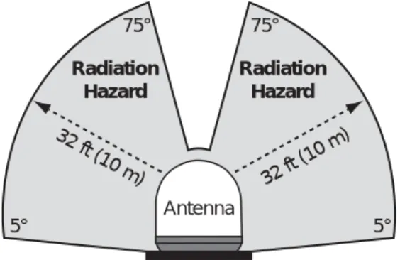
Caution - RF Radiation Hazard
The antenna transmits radio frequency (RF) energy that is potentially harmful. Whenever the system is powered on, make sure everyone stays more than 32 feet (10 m) away from the antenna. No hazard exists directly above the antenna and anywhere below the antenna’s mounting plane.
Figure 1-1 Minimum Safe Distance to Avoid Risk of RF Radiation Exposure
• If a person is standing outside the antenna’s main transmission
Radiation Hazard 32 ft (1 0 m) 5° Radiation Hazard 32 ft (10 m) 75° 75° 5° Antenna
6
Chapter 1 - Introduction
System Overview
Your TracPhone V3 is a complete mini-VSAT Broadband
communications system for mariners on the move. Using cutting-edge spread spectrum technology, which was previously only available to the military and corporate jets, the TracPhone V3 delivers a seamless and consistent Internet experience. And it all comes with an antenna that is much smaller and lighter than traditional VSAT antennas. As shown in the basic diagram below, the system consists of an antenna system, control unit, and modem that connect to a land-based hub via a Ku-band satellite. The hub, managed by a Network
Operations Center, then provides the link to the Internet and the terrestrial telephone network. A brief description of each system component is provided on the following page. A detailed wiring diagram is provided in “Wiring Diagram” on page 75.
Figure 1-2 TracPhone V3 mini-VSAT Broadband Network Diagram
Hub TracPhone Antenna Ku-band Satellite mini-VSAT Connection Control Unit & Modem
Network & VoIP Devices
VoIP Connection Ethernet Connection
Laptop PC Analog Phone
Customer-Supplied
Wireless Router
Internet Telephone Network
Chapter 1 - Introduction
System Components
The TracPhone V3 system includes the following components: The antenna unit provides the satellite link
between the onboard modem and the land-based hub. Using its integrated GPS, advanced reflector technology, and gyro stabilization, the antenna automatically locates and tracks the correct satellite, even while your vessel is on the move.
The control unit links the antenna to the modem and allows you to operate and configure all aspects of the system.
The modem, manufactured by ViaSat, is the transceiver and “brain” of the system. It processes all incoming and outgoing TCP/ IP data between the antenna and the switch using its proprietary spread spectrum technologies.
The multimedia terminal adapter (MTA) is a Voice over IP (VoIP) device that allows you to connect an analog telephone and make and receive calls over the mini-VSAT Broadband connection.
The switch links the system to your onboard local area network (LAN) via wired Ethernet connections. Four of its eight ports support Power over Ethernet (PoE) - they can supply power to any IEEE 802.3af-compliant device, such as a wireless access point.
8
Chapter 1 - Introduction
Service Activation
Before you can start using the TracPhone V3, you need to activate the system for mini-VSAT Broadband service. To activate, fill out and submit the following forms:
• KVH TracPhone V3 Service Activation Form
Complete the leisure or commercial form, as appropriate • End User Agreement
Read and initial each page in the bottom right-hand corner • Airtime Account Authorized Representative Form
Complete, if applicable
All forms are available in PDF format at www.kvh.com/mvbservice. The PDF versions include blank fields, allowing you to fill out the forms on your computer.
Fax or e-mail the completed forms to KVH:
Once KVH processes these forms, activates your account, and registers your product, you will receive an e-mail with the details of your new service, including phone numbers, as well as a link to create a
customer account on www.kvh.com. Your account will provide details of your TracPhone V3 system, links to your airtime and voice
accounts, and a wealth of information for your product, all in one convenient location.
North/South America, Australia:
Fax: +1 401 851-3823
E-mail: [email protected]
Europe, Middle East, Asia, Africa:
Fax: +45 45 160 181 E-mail: [email protected]
Chapter 2 - Operation
2. Operation
This chapter explains how to turn on and use the TracPhone V3 system.
It also explains how to interpret the startup screens.
Contents
Satellite Communication Basics... 11
Turning On the System ... 12
System Startup... 13
Using the mini-VSAT Broadband Service... 14
11 Chapter 2 - Operation
Satellite Communication Basics
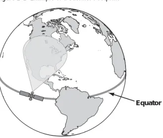
Ku-band communications satellites are located in fixed positions above the Earth’s equator and relay data to/from the earth within the regions that they serve. Therefore, to communicate via a given
satellite, you must be located within that satellite’s unique coverage area, also known as its “footprint.”
TIP: To view the latest mini-VSAT Broadband satellite coverage map, visit our website at www.kvh.com/minivsatmap.
Figure 2-1 Example of a Satellite Footprint
In addition, since satellites are located 22,300 miles (35,900 km) above the equator, the TracPhone antenna must have a clear view of the sky to transmit and receive signals. Anything that stands between the antenna and the satellite can block signals, resulting in lost data. Common causes of blockage include trees, buildings, and bridges. Heavy rain, ice, or snow may also temporarily interrupt reception.
Figure 2-2 Example of Satellite Blockage
Equator
Chapter 2 - Operation
Turning On the System
Follow the steps below to turn on your TracPhone system.
1. Make sure the antenna has a clear view of the sky. 2. Make sure power is applied to the modem, control unit,
switch, MTA, and computer(s).
3. Press the power button on the modem. The button’s
light should illuminate green.
Figure 2-3 Modem Front Panel Power Switch
4. Press the power button on the control unit. The button’s
light should illuminate green. The control unit supplies power to the antenna.
Figure 2-4 Control Unit Front Panel Power Switch
5. Turn on your networked computer(s).
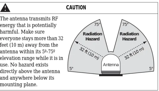
CAUTION
The antenna transmits RF energy that is potentially harmful. Make sure
everyone stays more than 32 feet (10 m) away from the antenna within its 5º-75º elevation range while it is in use. No hazard exists directly above the antenna and anywhere below its mounting plane. Radiation Hazard 32 ft (1 0 m) 5° Radiation Hazard 32 ft (10 m) 75° 75° 5° Antenna STATUS
13 Chapter 2 - Operation
System Startup
The control unit shows the following screens during startup. If the display shows an error message, see “Error Messages” on page 51.
Control Unit Screen Description
The antenna is running a self test routine
When GPS acquires a fix, momentarily displays your latitude/longitude
The antenna is waiting for the modem to initialize
The modem is communicating with the control unit
The modem is providing satellite identification data to the antenna The antenna is searching for the mini-VSAT Broadband service satellite
The antenna is now tracking the service satellite
The modem has accessed the mini-VSAT Broadband service; the system is ready for use!
ANTENNA INITIALIZING
GPS: ACQUIRED
41.5198N, 123.5817W
ANTENNA READY WAITING FOR MODEM
MODEM COMMS: OK
RECEIVING SATELLITE INFO FROM MODEM
SEARCHING FOR 72.0W SERVICE SATELLITE Note: Satellites will vary
TRACKING 72.0W SERVICE SATELLITE
Chapter 2 - Operation
Using the mini-VSAT Broadband Service
Once the TracPhone V3 modem establishes a connection with the mini-VSAT Broadband service, you can perform all of the same Internet tasks you perform at home:
• Internet browsing
• Weather and chart updates • Instant messaging
• Accessing corporate networks (VPNs) • Data transfers
NOTE: The system must be activated before you can use it. See “Service Activation” on page 8 for details.
Be sure to read all of the service terms and conditions in the End User Agreement, which can be found at www.kvh.com/
mvbservice.
15 Chapter 2 - Operation
Using KVH’s Enhanced Voice Service
The MTA and enhanced voice service allow you to make/receive calls via the mini-VSAT Broadband service. This section explains how to use the enhanced voice service.
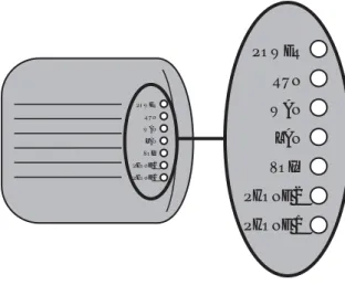
Turning On the MTA
The MTA has no on/off switch. When you turn on the TracPhone V3 system, the MTA initializes, which may take up to 15 minutes. The MTA is ready once its “VOIP” light is lit steady green (see Figure 2-5).
For complete details about the MTA device, refer to the MTA User’s Guide. Figure 2-5 MTA Status Lights
The TracPhone V3 voice service will not provide Automatic Number Identification or Automatic Location Information capabilities associated with emergency 911 or E911 services. In addition, the voice service will not work in the event of either a network service outage or a power failure. Therefore, it is critical that you maintain your vessel’s separate distress and safety communications system for emergency calls. Be sure to inform anyone who may use the TracPhone V3 of the limitations of 911 and E911 emergency services. The manufacturer, distributor, and
service provider shall not be liable for, and expressly disclaim, any direct or indirect damages, claims, losses, expenses, liabilities, actions, risks, or harms arising out of or related to the services provided through this equipment, including without limitation, emergency 911 or E911 services. IMPORTANT! POWER RUN WAN LAN VOIP PHONE 2 PHONE 1 POWER RUN WAN LAN VOIP PHONE 2 PHONE 1
Chapter 2 - Operation
Placing a Voice Call
For your convenience, you may assign a dial plan to the MTA that allows you to dial outgoing calls from the vessel to your home country as if they are in-country calls. For example, if Copenhagen is your home port, you could assign a Denmark dial plan to the MTA, allowing you to call home without the hassle of dialing an
international prefix and country code first. To assign a dial plan, access your voice account online (see “Managing Your Voice Account
Online” on page 19) and select “Dial Plan & Time Zone.”
To place a call, you need to dial the number as if you are calling from the chosen dial plan’s designated country (United States is the default), regardless of your vessel’s location. Follow the steps below.
1. Make sure the system is turned on and connected to the
mini-VSAT Broadband service (the control unit shows “Online”).
2. Make sure the “VOIP” light on the MTA is lit green. 3. Make sure another phone call is not in progress (the
“PHONE 1” light on the MTA is not lit green). The TracPhone V3 supports just one call at a time.
4. Pick up the handset on any phone connected to the
MTA’s “PHONE 1” jack. You should hear a dial tone.
5. Dial the phone number you wish to call. Within the dial plan’s country:
If you are calling a number within the dial plan’s country, dial it as an in-country call. For example, if your MTA is assigned a United States dial plan (default setting) and you are calling a U.S. number, dial Area/City Code + Local Phone Number.
Outside your dial plan’s country:
If you are calling a country that is outside your dial plan, dial it as an international call. For example, if your MTA is assigned a United States dial plan (default setting) and you are calling a number outside of the U.S., dial 011 + Country Code + Area/
City Code + Local Phone Number.
When you make a call via the mini-VSAT Broadband service, your voice travels 22,300 miles (35,900 km) into space, then 22,300 miles
17 Chapter 2 - Operation
Phone Numbers for Incoming Calls
During activation, your MTA’s phone line was assigned a phone number with the country code and area/city code of your choice. This allows people on shore within that region to call your vessel and avoid long distance or international calling charges, regardless of your vessel’s location.
For an additional monthly fee, you may associate up to five virtual “local numbers” to your MTA’s phone line, allowing people calling from additional countries to avoid long distance or international fees. For example, if you are running a business from your vessel, and you have many customers who live in France, you could set up a virtual number that allows customers in France to call your vessel using a French “local number.” To set up virtual phone numbers, contact KVH’s Airtime Services Department (see “Service Activation” on page 8 for contact information).
Chapter 2 - Operation
Recording a VoiceMail Personal Greeting
Follow the steps below to record your VoiceMail personal greeting.
1. Pick up the handset on any phone connected to the
MTA. You should hear a dial tone.
2. Dial 123# on the telephone keypad to connect to the
VoiceMail system.
3. Press 2 to access your mailbox.
4. Press 1 to access your personal greeting.
5. Press 2 to change your greeting. You will be prompted
to record your greeting.
6. Press 1 to listen to your personal greeting.
7. When you are satisfied with your greeting, press 3 to
accept and activate your greeting. You will hear the message “Your personal greeting has been activated.”
Listening to Your VoiceMail Messages
If the “PHONE 1” light on the MTA is blinking orange when the telephone handset is on the hook, you have new VoiceMail messages (see Figure 2-5 on page 15). Follow the steps below to listen to your VoiceMail messages.
1. Pick up the handset on any phone connected to the
MTA. You should hear a dial tone.
2. Dial 123# on the telephone keypad to connect to the
VoiceMail system.
3. Press 1 to listen to your messages.
4. Follow the spoken instructions to listen to, save, and/or
delete your messages.
NOTE: You can also listen to your messages online at your voice account web page (see “Managing Your Voice Account Online” on page 19). In addition, you can access VoiceMail from any regular landline telephone. Simply dial the number for your phone line, press *, then enter your PIN (provided during service activation).
19 Chapter 2 - Operation
Sending or Receiving a Fax
You can also fax documents via the enhanced voice service. Connect a fax machine to the “PHONE 1” jack on the MTA and dial as you would a voice call (see “Placing a Voice Call” on page 16).
NOTE: Faxing requires 70k bandwidth for sending and up to 90k bandwidth for receiving.
Faxing over Internet Protocol can be unreliable at times. Therefore, if you require an enterprise-grade fax solution, install KVH’s optional UCH-250 Fax Server (KVH part #19-0520). When you activate its corresponding fax service, the UCH-250 gives you an additional phone number dedicated for faxing, freeing up the “PHONE 1” jack on the MTA. Contact your dealer/distributor for details.
Managing Your Voice Account Online
You can manage your account online at your Enhanced Voice Service web page. You can view and configure all of the various calling features available to you, as well as view account information and listen to VoiceMails. To log onto the site, follow the steps below:
1. Go to http://kvh.myaccountcenter.net.
2. At the login page, enter your primary phone number
and PIN (provided during service activation).
NOTE: You may also navigate to this site from www.kvh.com/your-account. NOTE: You can also contact Customer Support by dialing 611 on your telephone handset.
Chapter 3 - Configuration
3. Configuration
This chapter explains how to change the brightness of the control unit’s
display, set up an RF radiation hazard zone, and reset the system to its
factory configuration. It also explains how to configure your computer
for a wired Ethernet connection to the TracPhone V3 system. For details
on setting up a wireless network, refer to the instructions provided with
your wireless access point (purchased separately).
Contents
Adjusting the Control Unit Display Brightness... 23
Configuring RF Radiation Hazard Zones ... 25
Resetting the System to Factory Conditions... 33
Configuring Your Computer for mini-VSAT Broadband.... 35
Requesting Static IP Addressing ... 43
23 Chapter 3 - Configuration
Adjusting the Control Unit Display Brightness
Follow the steps below to adjust the brightness of the control unit’s front panel display.
1. Press MENUS until the display shows
“CONFIGURATION.”
2. Press ACCEPT.
3. Press CHANGE until the display shows the desired
brightness setting: HIGH, MEDIUM, or LOW.
4. Press ACCEPT.
CONFIGURATION
NEXT MENU ACCEPT
BRIGHTNESS= HIGH
NEXT ITEM CHANGE
BRIGHTNESS= MEDIUM?
CHANGE ACCEPT
Chapter 3 - Configuration
25 Chapter 3 - Configuration
Configuring RF Radiation Hazard Zones
To prevent exposure to the antenna’s radiated RF energy, you can configure up to two RF radiation hazard zones for areas where crew and/or passengers frequent. (See “Important Safety Information” on page 5 for details on minimum safety distances.)
When determining the need for a hazard zone, keep in mind that the antenna transmits within an elevation range of 5°-75º. Therefore, you do not need to consider any areas that are below the antenna’s mounting plane, since they are safe from radiation exposure.
Figure 3-1 Example of an RF Radiation Hazard Zone
Whenever the antenna points within an RF radiation hazard zone, the system will disable the transmitter and the control unit will display the following message:
Once the antenna points outside the hazard zone, transmission capability will be restored.
Hazard Zone
080 015
RF RADIATION HAZARD!
TRANSMIT INHIBITED
Chapter 3 - Configuration
Defining an RF Radiation Hazard Zone
Follow the steps below to configure an RF radiation hazard zone.
1. Determine the necessary azimuth range for the RF
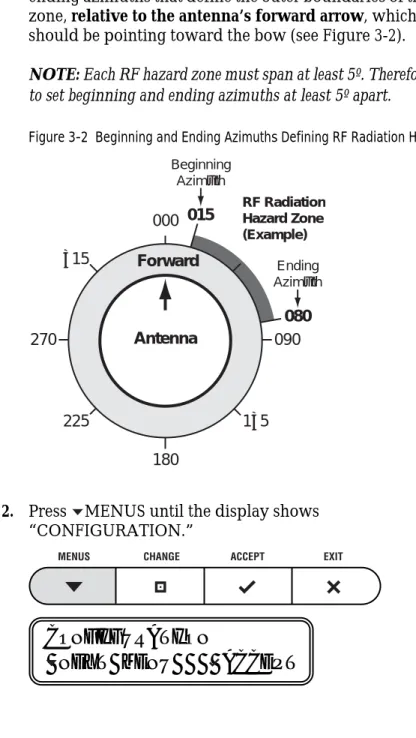
hazard zone. You will need to enter the beginning and ending azimuths that define the outer boundaries of the zone, relative to the antenna’s forward arrow, which should be pointing toward the bow (see Figure 3-2).
NOTE: Each RF hazard zone must span at least 5º. Therefore, be sure to set beginning and ending azimuths at least 5º apart.
Figure 3-2 Beginning and Ending Azimuths Defining RF Radiation Hazard Zone
2. Press MENUS until the display shows
“CONFIGURATION.” Antenna 000 180 090 270 135 225 315 Forward 015 080 RF Radiation Hazard Zone (Example) Beginning Azimuth Ending Azimuth
CONFIGURATION
27 Chapter 3 - Configuration
3. Press ACCEPT.
4. Press MENUS until the display shows “SET
HAZARD ZONE.”
5. Press CHANGE until the display shows “SET
HAZARD ZONE = YES.”
6. Press ACCEPT.
BRIGHTNESS= HIGH
NEXT ITEM CHANGE
SET HAZARD ZONE= NO
NEXT ITEM CHANGE
SET HAZARD ZONE=YES?
CHANGE ACCEPT
ZONE 1= 999-999
Chapter 3 - Configuration
7. Press CHANGE. A cursor appears under the first
number in the displayed azimuth range for RF radiation hazard zone #1. If no zone is currently configured, the display shows 999-999.
8. Press CHANGE until the number is set to the first
digit of the beginning azimuth for zone #1. If the azimuth
value is less than 100º, set the first digit to zero.
9. Press ACCEPT. The cursor moves to the next number.
10. Repeat steps 8 and 9 to set the remaining digits of the
range of azimuths for zone #1. Once you have set the entire range, the cursor disappears from the display.
11. Press ACCEPT. The display shows the current
azimuth range for RF radiation hazard zone #2.
ZONE 1= 999-999
CHANGE ACCEPT
ZONE 1= 099-999
CHANGE ACCEPT
ZONE 1= 015-080?
CHANGE ACCEPT
ZONE 2= 999-999
29 Chapter 3 - Configuration
12. If you wish to set up a second RF radiation hazard
zone, repeat steps 7-11. (Be sure the second zone does not
overlap the first.) Otherwise, press MENUS. The
display shows the current setting for Transmit Inhibition (“XMT IN ZONES”).
13. If the display shows “XMT IN ZONES = NO,” press
MENUS.
If the display shows “XMT IN ZONES = YES,” press
CHANGE until the display shows “XMT IN ZONES = NO.” Then press ACCEPT.
14. Press EXIT to exit the menu.
Make sure “XMT IN ZONES” is set to NO, so the antenna will not transmit whenever it points within one of your configured RF radiation hazard zones. If “XMT IN ZONES” is set to YES, the zones are disabled, allowing the antenna to transmit within them.
IMPORTANT!
XMT IN ZONES= NO
NEXT ITEM CHANGE
XMT IN ZONES= NO?
CHANGE ACCEPT
Chapter 3 - Configuration
Disabling RF Radiation Hazard Zones
If you wish to remove all restrictions on transmissions, follow the steps below to disable your programmed RF radiation hazard zones. This function simply disables the hazard zones; it does not delete them from memory.
NOTE: You can view the currently programmed hazard zones in the control unit’s Antenna Status menu (see “Antenna Status Information” on page 66).
1. Press MENUS until the display shows
“CONFIGURATION.”
2. Press ACCEPT.
CAUTION
Disabling RF radiation hazard zones allows the antenna to transmit in any direction, even if the antenna is pointing in an area accessible to passengers and crew. Make certain that everyone stays a
minimum safe distance away from the antenna before you transmit. Also be sure to return to this menu and restore the hazard zones when you are done transmitting.
CONFIGURATION
NEXT MENU ACCEPT
BRIGHTNESS= HIGH
NEXT ITEM CHANGE
31 Chapter 3 - Configuration
3. Press MENUS until the display shows “SET
HAZARD ZONE.”
4. Press CHANGE until the display shows “SET
HAZARD ZONE = YES.”
5. Press ACCEPT.
6. Press MENUS until the display shows “XMT IN
ZONES.”
SET HAZARD ZONE= NO
NEXT ITEM CHANGE
SET HAZARD ZONE=YES?
CHANGE ACCEPT
ZONE 1= 015-080
NEXT ITEM CHANGE
XMT IN ZONES= NO
NEXT ITEM CHANGE
Chapter 3 - Configuration
7. Press CHANGE until the display shows “XMT IN
ZONES = YES.”
8. Press ACCEPT.
9. Press EXIT to exit the menu.
XMT IN ZONES= YES?
CHANGE ACCEPT
WARNING: XMT ALLOWED
IN RF HAZARD ZONES
33 Chapter 3 - Configuration
Resetting the System to Factory Conditions
Follow the steps below to reset the TracPhone system to its original factory configuration.
1. Press MENUS until the display shows
“CONFIGURATION.”
2. Press ACCEPT.
3. Press MENUS until the display shows “FACTORY
RESET.”
CAUTION
Resetting the system clears all RF radiation hazard zones. The antenna will be able to transmit in any direction until you reprogram the hazard zones into the antenna.
CONFIGURATION
NEXT MENU ACCEPT
BRIGHTNESS= HIGH
NEXT ITEM CHANGE
FACTORY RESET= NO
NEXT ITEM CHANGE
Chapter 3 - Configuration
4. Press CHANGE until the display shows “FACTORY
RESET= YES.”
5. Press ACCEPT.
6. Press ACCEPT again to reset the system.
FACTORY RESET= YES?
CHANGE ACCEPT
RESET TO FACTORY?
ACCEPT EXIT
35 Chapter 3 - Configuration
Configuring Your Computer for mini-VSAT
Broadband
Follow the steps below to configure your computer for DHCP addressing. This will allow your computer to communicate with the modem via its Ethernet connection.
NOTE: If you wish to set up a wireless connection, set up and test a wired Ethernet connection first. Then purchase a wireless access point (WAP), connect it to the switch, and follow the wireless setup instructions provided with the WAP.
KVH Technical Support fully supports the four operating systems described here: Windows 7, Vista™, and XP, and Macintosh® OS X.
If the system is installed on a steel vessel, setting up a wireless connection might require a special WAP and the services of a technician with advanced networking expertise.
IMPORTANT!
When setting up a wireless network, be sure to apply security settings, such as encryption, to protect your network from outside intrusion. If your network is not secure, outsiders within range of your wireless network will be able to use your wireless connection without your knowledge.
Chapter 3 - Configuration
Windows 7 or Vista
Follow the steps below to configure a Windows 7 or Vista computer.
1. From the Windows Control Panel, navigate to the Network and Sharing Center. You can find the Control Panel either through the Start menu or “My Computer.” 2. At the Network and Sharing Center window,
double-click the Local Area Connection link (Windows 7) or
View Status link (Windows Vista) for the Ethernet
connection you are using for mini-VSAT Broadband.
Windows 7
37 Chapter 3 - Configuration
3. At the Local Area Connection Status window, click Properties. If this screen doesn’t appear, just skip to Step 4.
4. At the Local Area Connection Properties window,
select the Networking tab. Then select Internet
Chapter 3 - Configuration
5. At the Internet Protocol Properties window, select Obtain an IP address automatically and Obtain DNS server address automatically. Then click OK.
39 Chapter 3 - Configuration
Windows XP
Follow the steps below to configure a Windows XP computer.
1. At the Windows Control Panel, double-click the Network Connections icon. You can find the Control Panel either through the Start menu or “My Computer.” 2. At the Network Connections window, double-click the
Local Area Connection icon for the Ethernet
connection you are using for mini-VSAT Broadband.
3. At the Local Area Connection Status window, select the
General tab. Then click the Properties button. If this
Chapter 3 - Configuration
4. At the Local Area Connection Properties window,
select the General tab. Then select Internet Protocol
(TCP/IP) and click Properties.
5. At the Internet Protocol (TCP/IP) Properties window,
select the General tab. Then select Obtain an IP
address automatically and Obtain DNS server address automatically. Then click OK.
41 Chapter 3 - Configuration
6. At Local Area Connection Properties, click OK.
Chapter 3 - Configuration
Mac OS X
Follow the steps below to configure a Mac OS X computer.
1. At System Preferences, click the Network icon. 2. At the Network window, select the following:
• Show: Built-in Ethernet • Configure: Using DHCP • Leave all text boxes blank
43 Chapter 3 - Configuration
Requesting Static IP Addressing
At your request, KVH can enable static IP addressing for your TracPhone V3 system (a fee will apply). With a static IP address assigned to a computer system onboard your vessel, parties on shore will be able to access that computer directly over the Internet.
To request a static IP address, just fill out the online form at
www.kvh.com/mvbservice. Be sure to read all of the details on this form.
Once your static IP address is established, KVH will send you an e-mail containing your new static IP information, along with instructions on configuring your onboard computer.
A static IP address provides an open, unprotected connection to the Internet. Therefore, you should only assign a static IP address to a secure device, such as a firewall router.
Chapter 4 - Troubleshooting
4. Troubleshooting
This chapter identifies basic problems along with their possible causes
and solutions. It also explains what the status lights indicate, how to use
the diagnostic functions, and how to get technical support.
Contents
Five Simple Checks ... 47
Control Unit Status Lights... 48
Modem Status Light ... 50
Error Messages ... 51
Troubleshooting a Voice Service Problem ... 56
Viewing Status Information on Your Web Browser... 57
Viewing Status Information on the Control Unit... 63
Calibrating the Antenna Gyros... 70
Technical Support... 72
47 Chapter 4 - Troubleshooting
Five Simple Checks
If you are experiencing a problem with your TracPhone system, first check the five simple things below. If these checks do not lead you to the problem, contact KVH Technical Support for assistance (see
“Technical Support” on page 72).
Check #1: Are all lights on the control unit and modem lit green?
There are three status lights on the front panel of the control unit and one status light on the modem. If any of these lights are not lit green, see “Control Unit Status Lights” on page 48 and “Modem Status Light” on page 50 for failure indications.
Check #2: Are any error messages displayed on the control panel?
If the control panel is showing an error message, see “Error Messages” on page 51 for error definitions.
Check #3: Can the antenna find the satellite?
If the antenna is continuously searching for the satellite, check the area around the antenna for blockage. The antenna needs an unobstructed view of the sky to receive satellite signals. Common causes of blockage include buildings, bridges, mountains, and onboard equipment or structures. You can determine which direction the antenna is pointing by viewing the “ANTENNA AZ/EL” status on the control unit; see
“Antenna Status Messages” on page 67. If there is no blockage, you might be located outside of the mini-VSAT Broadband service coverage area (for details, visit www.kvh.com/minivsatmap).
Check #4: Are all system components powered on and connected
properly?
Make sure power is applied to all system components, including the modem, control unit, switch, and MTA. Also make sure all of the interconnecting cables are connected tightly.
Check #5: If you can’t connect via a wireless network, does a wired
connection work?
If you have a wireless network onboard, but you are unable to connect to the Internet while the TracPhone system is online, connect your computer directly to the switch via a straight-through (not crossover) Ethernet cable, then restart your computer. If you can then access the Internet, there is a problem with your wireless network.
Chapter 4 - Troubleshooting
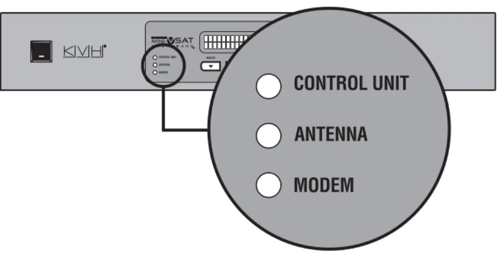
Control Unit Status Lights
Three status lights on the front of the control unit indicate the current status of the system and can help you identify problems quickly.
Figure 4-1 Control Unit Status Lights
During normal operation, all three status lights should be lit green. The following tables explain what the different light conditions indicate.
CONTROL UNIT Light
The table below explains what the CONTROL UNIT light indicates.
Light is... Indicates Description
Off Off Control unit is powered off or no power input
Green OK Good input power; control unit is operational
Orange Bad power Bad power supply circuit inside the control unit
Red Fault Error detected during control unit self test; try turning the control unit off, then back on
49 Chapter 4 - Troubleshooting
ANTENNA Light
The table below explains what the ANTENNA light indicates.
MODEM Light
The table below explains what the MODEM light indicates.
Light is... Indicates Description
Off Off No power input to the antenna Green Tracking Antenna is tracking a satellite Green,
flashing
Searching Antenna is searching for a satellite, or the modem is initializing
Red Fault Error detected; see error message on display
Light is... Indicates Description
Off Off Modem is powered off or initializing Green Online Modem is online and logged into the
mini-VSAT Broadband service Green,
flashing
Comms OK Modem is communicating with the antenna, but it is not yet online Orange Fault Error detected; see error message on
display
Red No comms Control unit has lost communications with the modem; check wiring
Chapter 4 - Troubleshooting
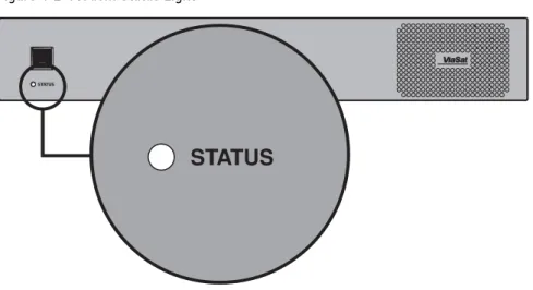
Modem Status Light
A status light on the front of the modem indicates the current status of the modem and can help you identify problems.
Figure 4-2 Modem Status Light
During normal operation, the status light should be lit green. The following table explains what the different light conditions indicate.
Light is... Indicates Description
Off Off Modem is powered off or initializing Green Online Modem is logged into the mini-VSAT
Broadband network Green,
flashing
Transmitting Modem is transmitting data or logging into the mini-VSAT Broadband network
Orange, flashing
Logging In Modem is logging into the mini-VSAT Broadband network
Red Searching or Fault
Antenna is searching for the service satellite, or error detected in modem; if antenna is tracking the service satellite, try turning the modem off, then back on
51 Chapter 4 - Troubleshooting
Error Messages
The table below lists error messages that might appear on the control unit display to indicate a system problem. Many of these faults should only be repaired by a KVH-certified technician; contact KVH Technical Support for assistance (see “Technical Support” on page 72).
Error Message Description
The antenna is unwrapping its internal cable; wait 30 seconds. The antenna’s azimuth motor or limit switch failed. Contact KVH Technical Support.
The control unit has lost communications with the
antenna. Check the wiring and try turning the control unit and modem off, then back on. If the error persists, contact KVH Technical Support.
The antenna’s elevation motor or limit switch failed. Contact KVH Technical Support.
The antenna is disabled because its temperature has risen above 85ºC. Turn off the system and allow it to cool down.
There is an open circuit in the antenna power/data cable. Check the cable.
There is a short circuit in the antenna power/data cable. Check the cable.
The antenna’s power supply circuit might have failed. Contact KVH Technical Support.
The antenna’s skew motor or limit switch failed. Contact KVH Technical Support. CABLE UNWRAP PLEASE WAIT ERROR: ANTENNA AZ ASSEMBLY ERROR:
ANTENNA COMM FAILURE
ERROR:
ANTENNA EL ASSEMBLY
ERROR:
ANTENNA OVERTEMP
ERROR:
ANTENNA POWER OPEN
ERROR:
ANTENNA POWER SHORT
ERROR:
ANTENNA POWER SUPPLY
ERROR:
Chapter 4 - Troubleshooting
There is an open circuit in the BUC power cable (between the control unit and the modem) or the transmit (TX) RF cable. Check the cables.
There is a short circuit in the BUC power cable (between the control unit and the modem) or the transmit (TX) RF cable. Check the cables.
The control unit has stopped supplying antenna and BUC power because its temperature has risen above 85ºC. Turn off the system and allow it to cool down. You might need to relocate the unit to an area that provides better ventilation.
The control unit is not supplying enough power to the antenna. Contact KVH Technical Support. The GPS is not communicating with the control unit. Try turning the control unit off, then back on. Also, check the terminal strip wiring at the control unit’s rear panel. If the error persists, the GPS module inside the antenna might need to be replaced. Contact KVH Technical Support. One of the antenna’s gyros is out of calibration. Try recalibrating the gyros (see “Calibrating the Antenna Gyros” on page 70). If a gyro fails to calibrate, contact KVH Technical Support. The gyro might need to be replaced.
Error Message Description
ERROR:
BUC POWER OPEN
ERROR:
BUC POWER SHORT
ERROR: CTRL UNIT OVERTEMP ERROR: CTRL UNIT PWR SUPPLY ERROR: GPS FAILURE ERROR:
53 Chapter 4 - Troubleshooting
The control unit has lost
communications with the modem. Ensure the modem is powered on and check the interconnecting cables. You can also try turning the modem off, then back on. If the error persists, contact KVH Technical Support.
The modem is not providing satellite signal strength data to the control unit. Try turning the modem off, then back on. If the error persists, contact KVH Technical Support.
The antenna’s LNB (low noise block) is not receiving 12-18 VDC from the modem’s “Rx RF” port. Ensure the modem is turned on and check the RX RF cable.
The control unit is not forwarding satellite signal strength data to the antenna. Try turning the control unit and modem off, then back on. If the error persists, contact KVH Technical Support.
The antenna’s RF software might be corrupted. Check the wiring and try turning the control unit and modem off, then back on. If the error persists, contact KVH Technical Support.
Your vessel is located outside the mini-VSAT Broadband coverage area, where service is unavailable (or you are located within a governmentally restricted area). Service will be restored once you reenter the coverage area.
Error Message Description
ERROR:
MODEM COMM FAILURE
ERROR:
MODEM RSSI FAILURE
ERROR: NO LNB POWER ERROR: RF RSSI FAILURE ERROR: RF SOFTWARE FAILURE OFFLINE OUTSIDE COVERAGE
Chapter 4 - Troubleshooting
The antenna is pointing within one of your programmed RF radiation hazard zones. See
“Configuring RF Radiation Hazard Zones” on page 25 for details.
The transmitter is temporarily disabled due to severe sea
conditions or excessive vibration. The system is not yet receiving valid position data from the GPS. It might take several minutes for the GPS to acquire a fix. If this message does not clear, check for antenna blockage and make sure the antenna’s radome is clear of grime. Also check for nearby radio antennas or radars, whose RF energy might interfere with GPS reception. You can also try turning the control unit off, then back on.
The modem does not detect a local area network (LAN) on its “User Enet” port. Make sure the switch is connected to the modem via a straight-through, not
crossover, cable.
The modem is disabled because its temperature has risen above 85ºC. Listen for the cooling fan inside the modem. If you don’t hear the fan, contact KVH
Technical Support. If you hear the fan, turn off the system, allow it to cool down, and vacuum the modem’s vents. You might also
Error Message Description
RF RADIATION HAZARD! TRANSMIT INHIBITED TRANSMIT INHIBITED BY CTRL UNIT WAITING FOR GPS WARNING:
MODEM LAN LINK DOWN
WARNING:
55 Chapter 4 - Troubleshooting
The modem is communicating OK with the control unit, but it is not providing any data to identify the service satellite. Wait a few minutes, then try turning the modem off, then back on. If the warning persists, contact KVH Technical Support.
Your vessel is located outside the mini-VSAT Broadband coverage area, where service is unavailable (or you are located within a governmentally restricted area). Service will be restored once you reenter the coverage area.
Error Message Description
WARNING:
NO SERVICE SAT INFO
WARNING:
Chapter 4 - Troubleshooting
Troubleshooting a Voice Service Problem
If you can access the Internet via the TracPhone system, but you are unable to make a voice call, try the five simple steps below.
Step #1: Make Sure You Are Dialing the Number Properly
As explained in “Placing a Voice Call” on page 16, if you are not calling the country that is currently set up as the MTA’s dial plan, you need to dial the appropriate international prefix(es) in addition to the local phone number in order to complete the connection. For example, if your MTA is set to a United States dial plan (default setting) and you are calling a number outside of the U.S., you need to dial 011 +
Country Code + Area Code + Local Phone Number.
Step #2: Reboot the MTA
The MTA might need to download an updated configuration file from the network. Unplug the power cord from the MTA. Wait 10 seconds, then plug it back in and wait for the device to initialize (it may take 15 minutes for the MTA to download the configuration file). Once the MTA’s “VOIP” light is lit steady green, try placing your call again.
Step #3: Verify the MTA Obtained an IP Address
The MTA must receive an IP address from the modem in order to provide a voice connection. Pick up the handset on any phone connected to the MTA and press ***1 on the keypad. If you hear “0.0.0.0” in the handset, the MTA did not receive a valid IP address. Contact KVH Technical Support for assistance (see “Technical Support” on page 72).
Step #4: Connect a Different Phone
Disconnect the phone from the MTA and connect another phone in its place (use a phone that you know is working properly). If you are then able to place a call with the new phone, the phone you were using is faulty.
57 Chapter 4 - Troubleshooting
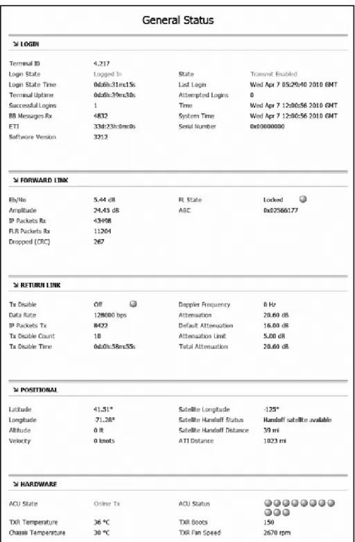
Viewing Status Information on Your Web Browser
Complete system status information is available via the modem’s local web interface. Simply open the web browser on any networked computer and enter the following web address:
http://192.168.0.1
As long as the modem is connected and functioning properly, the General Status page will display in your browser.
Chapter 4 - Troubleshooting
General Status: Login
The Login section provides the following helpful information:
Status Field Description
Terminal ID Last two octets of the modem’s external satellite IP address:
10.61.x.x; its identity on the
mini-VSAT Broadband network Login State Status of the network login:
• Logged In - Modem is logged into the network
• Logged out - Modem is logged out of the network; no user traffic will pass
• Waiting - Modem is attempting to log in; waiting for hub reply State Modem’s operating state; should
be “Transmit Enabled” while the antenna is tracking the service satellite
Login State Time
(days:hours:minutes:seconds)
Duration of the current Login State
Last Login Date/time of the modem’s last successful login to the network Terminal Uptime
(days:hours:minutes:seconds)
Length of time the modem has been in operation*
Attempted Logins Number of times the modem has attempted to log into the
network*
Successful Logins Number of times the modem has logged into the network*
BB Messages Rx Number of bulletin board
messages received from the hub*; should continuously increment while logged in
59 Chapter 4 - Troubleshooting
General Status: Forward Link
“Forward Link” refers to the communications path from the service hub to your vessel (downloads). The Forward Link section provides the following helpful information:
General Status: Return Link
“Return Link” refers to the communications path from your vessel to the service hub (uploads). The Return Link section provides the following helpful information:
Status Field Description
Eb/No Quality of the received signal; should be at least 2 dB; “No Lock” indicates satellite blockage or the antenna is searching for a satellite FL State Should be “Locked” and green
while the modem is logged in FLR Packets Rx Number of data packets received;
should continuously increment while logged in
Dropped (CRC) Dropped data packets due to errors; should not increment in large numbers
Status Field Description
Tx Disable Should be “Off” and green while tracking the service satellite, “On” and red when pointing within a configured RF hazard zone Data Rate Rate at which the modem is
capable of transmitting data; does
not indicate the actual data rate supported by your service plan Attenuation Set by the hub; the lower the
number, the higher your antenna’s transmission power; typically between 5-32 dB IP Packets Tx Number of data packets
Chapter 4 - Troubleshooting
General Status: Positional
The Positional section provides the following helpful information:
Status Field Description
Latitude, Longitude Your vessel’s position, reported by the antenna’s GPS
Satellite Longitude Longitude (orbital slot) of the current service satellite
Satellite Handoff Status Availability of an adjacent satellite for continued coverage: • Handoff satellite available - At
your vessel’s position, another satellite’s coverage area (footprint) overlaps your current satellite’s footprint • No satellite available - There
are no adjacent satellites; coverage will be lost once you travel outside the current satellite’s footprint
Satellite Handoff Distance Number of miles between your vessel’s position and the nearest boundary of your current
satellite’s footprint (this boundary
might not be located along your direction of travel)
61 Chapter 4 - Troubleshooting
General Status: Hardware
The Hardware section provides the following helpful information:
Status Field Description
ACU State Status of the antenna/control unit (ACU):
• Offline - Antenna/control unit is not communicating with the modem
• Signal Acquisition - Antenna is searching for the satellite • Online Tx Inhibit - Antenna is
tracking the service satellite, but inhibited from transmitting due to either an RF hazard zone or location in a restricted area • Online Tx - Antenna is tracking
the service satellite and allowed to transmit
ACU Status Health monitor of the antenna/ control unit; all LEDs should be green; if any LED is red, mouse over it to identify the fault Chassis Temperature Internal temperature of the
modem’s chassis (in °C)
TXR Fan Speed Current rotational speed (rpm) of the modem’s cooling fan; 0 rpm indicates a fan failure
Chapter 4 - Troubleshooting
Antenna and Control Unit Serial Numbers
While the modem’s serial number is provided on the General Status page, the serial numbers for the antenna and control unit (ACU) can be found on the ACU Status page (click the “ACU/Antenna” link in the sidebar).
Figure 4-4 ACU Status Page
NOTE: The General Status page provides all of the status information you might need to know, other than the two serial numbers noted above. All other status pages provide very detailed and advanced information that only KVH Technical Support might use for troubleshooting.
63 Chapter 4 - Troubleshooting
Viewing Status Information on the Control Unit
If you are unable to view the status information screens on the modem’s web interface, you can also view system status information on the control unit’s display. You can select either modem or antenna status information from the main menu.
Modem Status Information
1. Press MENUS until the display shows “MODEM
STATUS.”
2. Press ACCEPT to start viewing the modem status
screens.
3. Press MENUS to scroll forward through the status
messages. Press CHANGE to scroll backward. When you are done reviewing status messages, press EXIT.
MODEM STATUS
NEXT MENU ACCEPT
PRESS TO VIEW
EACH MODEM ITEM
MODEM STATE
ONLINE
Chapter 4 - Troubleshooting
Modem Status Messages
The table below lists all of the modem status messages.
Status Message Description
General status of the modem: • Online - Modem is connected
to the mini-VSAT Broadband service
• Offline - Modem is not connected to the service • Initializing
• Attempting Login • Waiting for Hub Comm • Transmit Disabled
Status of the Ethernet local area network (LAN) connection: • Link OK
• Link Down
Satellite currently selected for mini-VSAT Broadband service
Frequency of the satellite downlink (in GHz)
Polarization of the satellite downlink:
• Horizontal Linear • Vertical Linear
Quality of the received signal; Eb/No = Energy per bit/noise power per Hertz; must be greater than 2 dB for operation
External IP address of the
modem; identity of the modem on the mini-VSAT Broadband
MODEM STATE ONLINE
ETHERNET LAN STATUS LINK OK SERVICE SATELLITE 72.5W DOWNLINK FREQUENCY 11.840 GHZ DOWNLNK POLARIZATION HORIZONTAL EB/NO 08.6 dB MODEM SATELLITE IP 10.61.4.9
65 Chapter 4 - Troubleshooting
Local IP address of the modem on the vessel’s LAN
Subnet mask of the vessel’s LAN that is connected to the modem
Status of the modem’s DHCP server:
• Enabled - Modem is assigning IP addresses to clients on the LAN
• Disabled - IP addresses must be assigned manually to each client on the LAN
Temperature of the modem chassis
Modem serial number
Modem software version
Status Message Description
MODEM LAN IP 192.168.0.1
MODEM SUBNET MASK 255.255.255.0 MODEM DHCP STATUS ENABLED MODEM TEMPERATURE 50C MODEM SERIAL # 4:63 MODEM SW VERSION 3214
Chapter 4 - Troubleshooting
Antenna Status Information
1. Press MENUS until the display shows “ANTENNA
STATUS.”
2. Press ACCEPT to start viewing the antenna status
screens.
3. Press MENUS to scroll forward through the status
messages. Press CHANGE to scroll backward. When you are done reviewing status messages, press EXIT.
ANTENNA STATUS
NEXT MENU ACCEPT
PRESS TO VIEW
EACH ANTENNA ITEM
ANTENNA STATE
TRACKING
67 Chapter 4 - Troubleshooting
Antenna Status Messages
The table below lists all of the status messages.
Status Message Description
General status of the antenna: • Tracking
• Searching • Initializing
• Waiting for Modem
• Cable Unwrap - Unwrapping the internal cable; the cable can wrap up to 720º
• Idle • Error
Satellite that the modem has currently selected for tracking Azimuth and elevation at which the antenna is currently pointing, relative to the antenna’s
“Forward” arrow (bow) Current skew angle of the antenna’s LNB
Not applicable to TracPhone V3 systems
Status of the antenna’s GPS: • Position data - Latitude/
longitude reported by the GPS • Acquiring
• Comm Failure
Current setting for RF hazard zone #1
Current setting for RF hazard zone #2 ANTENNA STATE TRACKING CURRENT SATELLITE 72.5W ANTENNA AZ/EL AZ:229.1, EL:79.8 ANTENNA SKEW -68.4 TRUE HEADING NOT AVAILABLE GPS STATUS 41.5198N, 123.5817W RF HAZARD ZONE 1 335-025 RF HAZARD ZONE 2 225-265
Chapter 4 - Troubleshooting
Current setting for XMT in Zones: • No - Transmission is inhibited
if antenna points within a zone • Yes - Transmission unrestricted DC voltage measured at the antenna’s circuit board; should be greater than 39 VDC
DC voltage measured at the control unit’s power input; should be greater than 12.5 VDC
Status of the antenna’s BUC (transmit) power:
• On - BUC power is applied; also reports actual measured power • Off - BUC power is disabled Should be greater than 20 VDC Antenna model
Antenna serial number
Main software version
RF software version
Azimuth/elevation motor software version
Skew motor software version
Status Message Description
XMT IN ZONES NO ANTENNA DC INPUT 41.2 VDC CTRL UNIT DC INPUT 13.4 VDC BUC POWER ON 21.4 VDC ANTENNA MODEL TRACPHONE V3 ANTENNA SERIAL # 070901234
ANTENNA MAIN BOARD SW VERSION 2.34
ANTENNA RF BOARD SW VERSION 1.23
ANTENNA AZ/EL MOTOR SW VERSION 1.28
ANTENNA SKEW MOTOR SW VERSION 1.04
69 Chapter 4 - Troubleshooting
Control unit software version
Status Message Description
CTRL UNIT
Chapter 4 - Troubleshooting
Calibrating the Antenna Gyros
The TracPhone antenna’s gyros continuously measure the motion of your vessel and send this data to the antenna’s motor control circuitry to keep the antenna pointed at the satellite. At the factory, each antenna gyro is precisely calibrated to work with the antenna’s circuit board. Therefore, if you ever have a gyro or circuit board replaced, you will need to recalibrate the gyros for the new part.
Follow the steps below to calibrate the gyros.
1. Press MENUS until the display shows
“DIAGNOSTICS.”
2. Press ACCEPT to enter the Diagnostics menu.
Calibrate the gyros only if directed by KVH Technical Support, and only while the vessel is stationary. A poor gyro calibration can reduce the performance of the antenna.
IMPORTANT!
DIAGNOSTICS
NEXT MENU ACCEPT
ENTERING DIAGNOSTICS
CAL GYRO= NO
71 Chapter 4 - Troubleshooting
3. Press CHANGE until the display shows “CAL
GYRO= YES.”
4. Press ACCEPT to start gyro calibration.
5. Verify that the azimuth (AZ), elevation (EL), and skew
gyros all pass (“P”). If any gyro fails (“F”), retry the calibration. If it continues to fail, please seek technical support (see “Technical Support” on page 72).
6. Once the gyros are calibrated, the antenna restarts. Wait
five minutes for system startup.
CAL GYRO= YES?
CHANGE ACCEPT
DO NOT MOVE VESSEL
DURING CALIBRATION
CALIBRATING GYROS
AZ: EL: SKEW:
CALIBRATING GYROS
AZ:P EL:P SKEW:P
Chapter 4 - Troubleshooting
Technical Support
The TracPhone V3 system is a sophisticated electronic device; only specially trained KVH-certified technicians have the tools and
expertise necessary to diagnose and repair a system fault. Therefore, if you experience an operating problem or require technical assistance, please contact KVH Technical Support (24/7):
Please have your system serial numbers handy before you call. You can get these serial numbers from the control unit’s Modem Status and Antenna Status menus.
Within the Continental U.S.A.:
Phone: 1 866 701-7103 (via landline) E-mail: [email protected]
North/South America, Australia:
Phone: +1 401 851-3806
E-mail: [email protected]
Europe, Middle East, Asia, Africa:
Phone: +45 45 160 180 E-mail: [email protected]