Administrator Guide i
Service and Support Information
Product Version
This manual applies to version 4.0 of the BIG-IP® Controller.
Obtaining Technical Support
Contacting F5 Networks
Web tech.f5.com
Phone (206) 272-6888
Fax (206) 272-6802
Email (support issues)
Email (suggestions) [email protected]
Web www.f5.com
Toll-free phone (888) 961-7242
Corporate phone (206) 272-5555
Fax (206) 272-5556
Email [email protected]
Mailing Address 401 Elliott Avenue West Seattle, Washington 98119
F5 Networks, Inc. (F5) believes the information it furnishes to be accurate and reliable. However, F5 assumes no responsibility for the use of this information, nor any infringement of patents or other rights of third parties which may result from its use. No license is granted by implication or otherwise under any patent, copyright, or other intellectual property right of F5 except as specifically described herein. F5 reserves the right to change specifications at any time without notice.
Copyright 1997-2001, F5 Networks, Inc. All rights reserved.
Trademarks
F5, BIG-IP, 3-DNS, SEE-IT, and GLOBAL-SITE are registered trademarks of F5 Networks, Inc. EDGE-FX, iControl, and FireGuard are trademarks of F5 Networks, Inc. Other product and company names are registered trademarks or trademarks of their respective holders.
Export Regulation Notice
The BIG-IP® Controller may include cryptographic software. Under the Export Administration Act, the United States government may consider it a criminal offense to export this BIG-IP® Controller from the United States.
Export Warning
This is a Class A product. In a domestic environment this product may cause radio interference in which case the user may be required to take adequate measures.
FCC Compliance
This equipment generates, uses, and may emit radio frequency energy. The equipment has been type tested and found to comply with the limits for a Class A digital device pursuant to Part 15 of FCC rules, which are designed to provide reasonable protection against such radio frequency interference.
Operation of this equipment in a residential area may cause interference, in which case the user at his own expense will be required to take whatever measures may be required to correct the interference.
Any modifications to this device, unless expressly approved by the manufacturer, can void the user's authority to operate this equipment under part 15 of the FCC rules.
Canadian Regulatory Compliance
This class A digital apparatus complies with Canadian I CES-003.
Standards Compliance
Administrator Guide iii Acknowledgments
This product includes software developed by the University of California, Berkeley and its contributors. This product includes software developed by the Computer Systems Engineering Group at the Lawrence Berkeley Laboratory.
This product includes software developed by the NetBSD Foundation, Inc. and its contributors. This product includes software developed by Christopher G. Demetriou for the NetBSD Project. This product includes software developed by Adam Glass.
This product includes software developed by Christian E. Hopps. This product includes software developed by Dean Huxley. This product includes software developed by John Kohl. This product includes software developed by Paul Kranenburg. This product includes software developed by Terrence R. Lambert. This product includes software developed by Philip A. Nelson. This product includes software developed by Herb Peyerl.
This product includes software developed by Jochen Pohl for the NetBSD Project. This product includes software developed by Chris Provenzano.
This product includes software developed by Theo de Raadt. This product includes software developed by David Muir Sharnoff. This product includes software developed by SigmaSoft, Th. Lockert.
This product includes software developed for the NetBSD Project by Jason R. Thorpe.
This product includes software developed by Jason R. Thorpe for And Communications, http://www.and.com. This product includes software developed for the NetBSD Project by Frank Van der Linden.
This product includes software developed for the NetBSD Project by John M. Vinopal. This product includes software developed by Christos Zoulas.
This product includes software developed by Charles Hannum.
This product includes software developed by Charles Hannum, by the University of Vermont and State Agricultural College and Garrett A. Wollman, by William F. Jolitz, and by the University of California, Berkeley, Lawrence Berkeley Laboratory, and its contributors.
This product includes software developed by the University of Vermont and State Agricultural College and Garrett A. Wollman.
In the following statement, "This software" refers to the Mitsumi CD-ROM driver: This software was developed by Holger Veit and Brian Moore for use with "386BSD" and similar operating systems. "Similar operating systems" includes mainly non-profit oriented systems for research and education, including but not restricted to "NetBSD," "FreeBSD," "Mach" (by CMU).
In the following statement, "This software" refers to the parallel port driver: This software is a component of "386BSD" developed by William F. Jolitz, TeleMuse.
This product includes software licensed from Richard H. Porter under the GNU Library General Public License (© 1998, Red Hat Software), www.gnu.org/copyleft/lgpl.html.
This product includes the standard version of Perl software licensed under the Perl Artistic License (© 1997, 1998 Tom Christiansen and Nathan Torkington). All rights reserved. You may find the most current standard version of Perl at http://www.perl.com.
Introduction
Getting started ...Intro-1 Choosing a configuration tool ... Intro-1 Using the Administrator Kit ...Intro-2 Stylistic conventions ...Intro-3 Finding additional help and technical support resources ... Intro-6 What’s new in version 4.0 ... Intro-7 3-DNS on the BIG-IP Controller ... Intro-7 OneConnect™ content switching with HTTP Keep-Alives ...Intro-7 Bridging and Layer 2 forwarding ... Intro-7 HTTP Redirect pool property ... Intro-8 Load balance any IP protocol ... Intro-8 Link aggregation and fail-over ... Intro-8 On-the-fly content converter ... Intro-8 SNAT automap feature ...Intro-9 Health monitors ... Intro-9 Performance monitors ... Intro-9 Default controller configuration ... Intro-9 Web-based Configuration utility enhancements ...Intro-10 Learning more about the BIG-IP Controller product family ...Intro-10
1
BIG-IP Controller Overview
Introduction ...1-1 User interface ... 1-1 A basic configuration ... 1-3 Configuring objects and object properties ...1-5 Load balancing modes ... 1-7 BIG-IP Controllers and intranets ... 1-8 Bidirectional load balancing ... 1-9 Cache control ...1-11 SSL acceleration ...1-12 Content conversion ...1-12 VLANs ...1-12 Link aggregation and link failover ...1-13 Configuring redundant BIG-IP Controller pairs ...1-13 Making hidden nodes accessible ...1-14 Forwarding ...1-14 Address translation ...1-14 Monitoring and administration ...1-15 Health monitors ...1-15
Table of Contents
viii BIG-IP® Controller 4.0
2
Basic Web Site and E-Commerce Configuration
Working with a basic web site and e-commerce configuration ... 2-1 Configuring a basic e-commerce site ...2-2 Defining the pools ... 2-2 Defining the virtual servers ... 2-4 Additional configuration options ... 2-5
3
Installing a BIG-IP Controller without Changing the IP Network
Installing a BIG-IP Controller without changing IP networks ... 3-1 Configuring the controller for the same IP network ... 3-2 Additional configuration options ... 3-8
4
A Simple Intranet Configuration
Working with a simple intranet configuration ... 4-1 Creating the simple intranet configuration ...4-3 Defining the pools ... 4-3 Defining the virtual servers ... 4-4 Additional configuration options ... 4-5
5
Load Balancing ISPs
Using ISP load balancing ... 5-1 Configuring ISP load balancing ... 5-2 Configuring network address translation on routers ... 5-4 Enabling service 80 and service 443 ... 5-6 Additional configuration options ... 5-6
6
Load Balancing VPNs
Working with VPN load balancing ... 6-1 Configuring VPN load balancing ...6-2 Using VPN and router load balancing ... 6-5 Configuring virtual servers for VPN and router load balancing ... 6-5 Configuring VPN and router load balancing ... 6-7 Additional configuration options ...6-12
7
Using IPSEC with VPN Gateways
Configuring load balancing between VPN gateways ... 7-1 Configuring IPSEC load balancing ... 7-3 The VPN sandwich configuration with IPSEC ...7-6 Additional configuration options ... 7-9
8
Configuring an SSL Accelerator
Introducing the SSL Accelerator ... 8-1 Configuring the SSL Accelerator ... 8-2 Generating a key and obtaining a certificate ... 8-3 Installing certificates from the certificate authority (CA) ...8-9 Creating a pool for the HTTP servers ...8-11 Creating an HTTP virtual server ...8-12 Creating an SSL gateway ...8-13 Introducing the SSL accelerator scalable configuration ...8-16 Creating the scalable SSL accelerator configuration ...8-18 Configuring the BIG-IP Controller that load balances the SSL
accelerators ...8-18 Configuring the SSL accelerators ...8-23 Additional configuration options ...8-24
9
Balancing Two-Way Traffic Across Firewalls
Introducing two-way firewall load balancing ... 9-1 Configuring two-way firewall load balancing ... 9-3 Configuring routing to the internal network ... 9-3 Creating pools for firewalls and servers ... 9-3 Creating a pool for outside firewall interfaces ... 9-4 Creating a pool for inside firewall interfaces ... 9-5 Creating a pool for servers ... 9-6 Creating virtual servers for inbound traffic ... 9-7 Creating a network virtual server to load balance the firewalls ... 9-7 Enhancing security for this configuration ... 9-9 Creating a standard virtual server to load balance intranet servers ... 9-9 Creating virtual servers for outbound traffic ...9-10
Creating a wildcard virtual server for balancing traffic to the
firewalls ...9-11 Creating a forwarding wildcard virtual server to forward traffic
Table of Contents
x BIG-IP® Controller 4.0
Configuring administrative routing ...9-14 Additional configuration options ...9-14
10
Load Balancing a Cache Array for Local Server Acceleration
Introducing local server acceleration ...10-1 Maximizing memory or processing power ...10-2 Using the configuration diagram ...10-3 Configuring local acceleration ...10-3 Creating pools ...10-4 Creating a pool for the cache servers ...10-5 Creating a pool for the origin server ...10-6 Creating a pool for hot content ...10-7 Creating a cache rule ...10-8 Using a cacheable content expression ...10-9 Setting content demand status ... 10-11 Creating a virtual server ... 10-12 Configuring for intelligent cache population ... 10-13 Configuring a SNAT ... 10-14 Additional configuration options ... 10-15
11
Load Balancing a Cache Array for Remote Server Acceleration
Introducing remote server acceleration ...11-1 Maximizing memory or processing power ...11-3 Configuring remote server acceleration ...11-3 Creating pools ...11-4 Creating a pool for the cache servers ...11-5 Creating a pool for the origin server ...11-6 Creating a pool for hot content ...11-7 Creating a cache rule ...11-8 Working with a cacheable content expression ...11-8 Understanding content demand status ... 11-11 Creating a virtual server ... 11-12 Configuring for intelligent cache population ... 11-13 Configuring a SNAT ... 11-14 Configuring a SNAT automap for bounceback ... 11-15 Additional configuration options ... 11-16
12
Configuring Forward Proxy Caching
Introducing forward proxy caching ...12-1 Maximizing memory or processing power ...12-2 Using the configuration diagram ...12-2 Configuring forward proxy caching ...12-3 Creating pools ...12-4 Creating a pool for the cache servers ...12-5 Creating a pool for the origin server ...12-6 Creating a pool for hot content ...12-7 Creating a cache rule ...12-8 Working with a cacheable content expression ...12-8 Understanding content demand status ... 12-10 Creating a virtual server ... 12-12 Additional configuration options ... 12-13
13
Configuring a Content Converter
Introducing the content converter ...13-1 Configuring the content converter ...13-3 Configuring the on-the-fly conversion software ...13-3 Creating the load balancing pool ...13-4 Creating the virtual server ...13-5 Creating a content converter gateway using the Configuration
utility ...13-6 Enabling, disabling, or deleting a content converter gateway ...13-7 Displaying the configuration for a content converter gateway
from the command line ...13-8 Additional configuration options ...13-9
14
Hosting Multiple Sites
Introducing multiple site hosting ...14-1 Configuring multiple site hosting ...14-1 Creating VLAN tags ...14-2 Creating the server pools to load balance ...14-3 Creating the virtual server to load balance the web servers ...14-4 Additional configuration options ...14-4
Table of Contents
xii BIG-IP® Controller 4.0
15
Using Link Aggregation with Tagged VLANs
Introducing link aggregation with tagged VLANs ...15-1 Using the two-network aggregated tagged VLAN topology ...15-1 Configuring the two-network topology ...15-2 Aggregating the links ...15-3 Creating VLAN tags ...15-4 Creating the pool of web servers to load balance ...15-5 Creating the virtual server to load balance the web servers ...15-5 Using the one-network aggregated tagged VLAN topology ...15-6 Configuring the one-network topology ...15-7 Creating a VLAN group ...15-8 Creating a self IP for the VLAN group ...15-9 Additional configuration options ...15-9
16
One IP Network Topologies
Introducing the one-IP network topology ...16-1 Setting up a one-IP network topology with one interface ...16-2 Defining the pools for an additional Internet connection ...16-2 Defining the virtual server ...16-3 Configuring the client SNAT ...16-3 Additional configuration options ...16-4
17
nPath routing
Introducing nPath routing ...17-1 Defining a server pool for nPATH routing ...17-3 Defining a virtual server with address translation disabled ...17-4 Configuring the virtual server on the content server loopback
interface ...17-5 Setting the route for inbound traffic ...17-5 Setting the return route ...17-5 Setting the idle connection time-out ...17-6 Additional configuration options ...17-7
18
Monitoring and Administration
Monitoring and administration utilities ...18-1 Using the bigpipe utility as a monitoring tool ...18-2 Monitoring the BIG-IP Controller ...18-2 Monitoring virtual servers, virtual addresses and services ... 18-10 Monitoring nodes and node addresses ... 18-12 Monitoring NATs ... 18-13 Monitoring SNATs ... 18-14 Viewing the status of the interface cards ... 18-14 Using the Configuration utility for administration and monitoring ... 18-15 Adding a user ... 18-15 Customizing the Configuration utility ... 18-15 Configuring SNMP ... 18-16 Working with the BIG/top utility ... 18-16 Using BIG/top command options ... 18-17 Using runtime commands in BIG/top ... 18-17 Working with the Syslog utility ... 18-18 Sample log messages ... 18-18 Removing and returning items to service ... 18-19 Removing the BIG-IP Controller from service ... 18-20 Removing individual virtual servers, virtual addresses, and
ports from service ... 18-21 Removing individual nodes and node addresses from service ... 18-22 Viewing the currently defined virtual servers and nodes ... 18-22 Viewing system statistics and log files ... 18-22 Viewing system statistics ... 18-23 Viewing log files ... 18-23 Printing the connection table ... 18-24 Changing passwords ... 18-24
Changing passwords and adding new user IDs for the
web-based Configuration utility ... 18-24 Working with the BIG/db database ... 18-26 Using the bigpipe db command ... 18-26 Working with the BIG/stat utility ... 18-28
19
Configuring SNMP
Working with SNMP ...19-1 Getting started with SNMP ...19-2 Downloading the MIBs ...19-2
Table of Contents
xiv BIG-IP® Controller 4.0
Configuring SNMP settings ...19-4 Downloading the MIBs ...19-5 /etc/hosts.deny ...19-6 /etc/hosts.allow ...19-6 /etc/snmpd.conf ...19-8 /etc/snmptrap.conf ... 19-11 Syslog ... 19-12 Enable the SNMP port ... 19-12
Glossary
Index
• Getting started
• Using the Administrator Kit
• What’s new in version 4.0
Introduction
Administrator Guide Intro - 1
Getting started
Before you start installing the controller, we recommend that you browse the BIG-IP Administrator Guide and find the load balancing solution that most closely addresses your needs. If the BIG-IP Controller is running the 3-DNS software module, you may also want to browse the 3-DNS Administrator Guide to find a wide area load balancing solution. Briefly review the basic
configuration tasks and the few pieces of information, such as IP addresses and host names, that you should gather in preparation for completing the tasks.
Once you find your solution and gather the necessary network information, turn back to the Installation Guide for hardware installation instructions, and then return to the Administrator Guide to follow the steps for setting up your chosen solution.
Choosing a configuration tool
The BIG-IP Controller offers both web-based and command line configuration tools, so that users can work in the environment that they are most comfortable with.
The First-Time Boot utility
All users will use the First-Time Boot utility, a wizard that walks you through the initial system set up. You can run the First-Time Boot utility from the command line, or from a web browser. The First-Time Boot utility prompts you to enter basic system information including a root password and the IP addresses that will be assigned to the network interfaces. The BIG-IP Installation Guide provides a list of the specific pieces of information that the First-Time Boot utility prompts you to enter.
The Configuration utility
The Configuration utility is a web-based application that you use to configure and monitor the load balancing setup on the BIG-IP Controller. Once you complete the installation instructions described in this guide, you can use the Configuration utility to
perform the configuration steps necessary for your chosen load balancing solution. In the Configuration utility, you can also monitor current system performance, and download administrative tools such as the SNMP MIB or the SSH client. The Configuration utility requires Netscape Navigator version 4.7 or later, or
Microsoft Internet Explorer version 5.0 or later.
The bigpipe and bigtop command line utilities
The bigpipe™ utility is the command line counter-part to the Configuration utility. Using bigpipe commands, you can configure virtual servers, open ports to network traffic, and configure a wide variety of features. To monitor the BIG-IP Controller, you can use certain bigpipe commands, or you can use the bigtop™ utility, which provides real-time system monitoring. You can use the command line utilities directly on the BIG-IP Controller console, or you can execute commands via a remote shell, such as the SSH client (encrypted communications only), or a Telnet client (for countries restricted by cryptography export laws). For detailed information about the command line syntax, seethe BIG-IP Reference Guide, Chapter 2, bigpipe Command Reference, and the
BIG-IP Administrator Guide, Chapter 18, Monitoring and Administration.
Using the Administrator Kit
The BIG-IP® Administrator Kit provides all of the documentation you need to work with the BIG-IP Controller. The information is organized into the guides described below.
◆ BIG-IP Installation Guide
This guide walks you through the basic steps needed to get the hardware plugged in and the system connected to the network. Most users turn to this guide only the first time that they set up a controller. The BIG-IP Installation Guide also covers general network administration issues, such as setting up common network administration tools including Sendmail.
Introduction
Administrator Guide Intro - 3
◆ BIG-IP Administrator Guide
This guide provides examples of common load balancing solutions, as well as additional administrative information. Before you begin installing the controller hardware, we recommend that you browse this guide to find the load balancing solution that works best for you.
◆ BIG-IP Reference Guide
This guide provides basic descriptions of individual BIG-IP objects, such as pools, nodes, and virtual servers. It also provides syntax information for bigpipe commands, other command line utilities, configuration files, and system utilities. ◆ F-Secure SSH User Guide
This guide provides information about installing and working with the SSH client, a command line shell that supports remote encrypted communications. The SSH client and corresponding user guide is distributed only with BIG-IP Controllers that support encryption.
◆ 3-DNS Administrator and Reference Guides
If your BIG-IP Controller includes the optional 3-DNS software module, your administrator kit also includes manuals for using 3-DNS Controller software. The 3-DNS Administrator Guide
provides wide area load balancing solutions and general administrative information. The 3-DNS Reference Guide
provides information about configuration file syntax and system utilities specific to the 3-DNS Controller.
Stylistic conventions
To help you easily identify and understand important information, our documentation uses the stylistic conventions described below.
Using the solution examples
All examples in this documentation use only non-routable IP addresses. When you set up the solutions we describe, you must use IP addresses suitable to your own network in place of our sample addresses.
Identifying new terms
To help you identify sections where a term is defined, the term itself is shown in bold italic text. For example, a virtual server is a specific combination of a virtual address and virtual port,
associated with a content site that is managed by a BIG-IP Controller or other type of host server.
Identifying references to objects, names, and commands
We apply bold text to a variety of items to help you easily pick them out of a block of text. These items include web addresses, IP addresses, utility names, and portions of commands, such as variables and keywords. For example, with the bigpipe pool <pool_name> show command, you can specify a specific pool to show by specifying a pool name for the <pool_name> variable.
Identifying references to other documents
We use italic text to denote a reference to another document. In references where we provide the name of a book as well as a specific chapter or section in the book, we show the book name in bold, italic text, and the chapter/section name in italic text to help quickly differentiate the two. For example, you can find
information about bigpipe commands in the BIG-IP Reference Guide,Chapter 1, bigpipe Command Reference.
Identifying command syntax
We show complete commands in bold Courier text. Note that we do not include the corresponding screen prompt, unless the command is shown in a figure that depicts an entire command line screen. For example, the following command shows the
configuration of the specified pool name: bigpipe pool <pool_name> show
or
Introduction
Administrator Guide Intro - 5
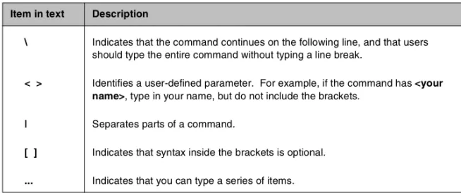
Table Intro.1 explains additional special conventions used in command line syntax.
Item in text Description
\ Indicates that the command continues on the following line, and that users should type the entire command without typing a line break.
< > Identifies a user-defined parameter. For example, if the command has <your name>, type in your name, but do not include the brackets.
| Separates parts of a command.
[ ] Indicates that syntax inside the brackets is optional.
... Indicates that you can type a series of items. Table Intro.1 Command line syntax conventions
Finding additional help and technical support resources
You can find additional technical information about this product in the following locations:
◆ Release notes
Release notes for the current version of this product are available from the product web server home page, and are also available on the technical support site. The release notes contain the latest information for the current version, including a list of new features and enhancements, a list of fixes, and, in some cases, a list of known issues.
◆ Online help
You can find help online in three different locations:
• The web server on the product has PDF versions of the guides included in the Administrator Kit.
• The web-based Configuration utility has online help for each screen. Simply click the Help button.
• Individual bigpipe commands have online help, including command syntax and examples, in standard UNIX man page format. Simply type the command followed by the word help, and the BIG-IP Controller displays the syntax and usage associated with the command.
◆ Third-party documentation for software add-ons
The web server on the product contains online documentation for all third-party software, such as GateD.
◆ Technical support via the World Wide Web The F5 Networks Technical Support web site,
http://tech.F5.com, provides the latest technical notes, answers to frequently asked questions, updates for administrator guides (in PDF format), and the Ask F5 natural language question and answer engine. To access this site, you need to obtain a customer ID and a password from the F5 Help Desk.
Introduction
Administrator Guide Intro - 7
What’s new in version 4.0
The BIG-IP Controller offers the following major new features in version 4.0, in addition to many smaller enhancements.
3-DNS on the BIG-IP Controller
With this release of the BIG-IP Controller, you can order the full wide-area load balancing functionality of the 3-DNS Controller combined with the local-area load balancing functionality of the BIG-IP Controller. An advantage you gain with this configuration is that the combined configuration requires less rack space.
OneConnect™ content switching with HTTP Keep-Alives
OneConnect content switching allows you to turn on the Keep-Alive functionality on your Web servers.You can now configure BIG-IP Controller rules to support HTTP 1.1 Keep-Alive functionality. This feature allows you to benefit from the Keep-Alive features on your Web servers.
Another benefit of this feature is client aggregation. You can aggregate client connections by configuring a SNAT for inbound requests. This reduces the number of connections from the BIG-IP Controller to back-end servers and from clients to the BIG-IP Controller.
Bridging and Layer 2 forwarding
The bridging and Layer 2 forwarding functionality in this release provides the ability to bridge packets between VLANs and between VLANs on the same IP network. The layer 2 forwarding feature provides the ability to install a BIG-IP Controller without changing the IP network configuration. For an example of how to use layer 2 forwarding, see VLAN group in the BIG-IP Reference Guide, Chapter 1, Configuring the BIG-IP Controller.
HTTP Redirect pool property
The HTTP redirect feature adds the ability to redirect clients to another site or server or to a 3-DNS Controller when the members of a pool they were destined for are not available. For more information, see HTTP Redirect (specifying a fallback host) inthe
BIG-IP Reference Guide, Chapter 1, Configuring the BIG-IP Controller.
Load balance any IP protocol
The load balance any IP protocol feature provides the ability to load balance IP protocols other than TCP or UDP. This means that you can load balance VPN client connections across a number of VPNs, eliminating the possibility of a single point of failure. For more information, see Chapter 7, Using IPSEC with VPN Gateways.
Link aggregation and fail-over
The link aggregation, and related fail-over, feature provides the ability to combine multiple Ethernet links into a single trunk. This allows you to increase available bandwidth incrementally and improve link reliability. For more information, see Trunks in the
BIG-IP Reference Guide, Chapter 1, Configuring the BIG-IP Controller.
On-the-fly content converter
The on-the-fly content converter provides a simplified method of converting URLs in HTML files passing through the BIG-IP Controller to ARLs that point to the Akamai Freeflow NetworkTM.
For more information, see Chapter 13, Configuring a Content Converter.
Introduction
Administrator Guide Intro - 9
SNAT automap feature
The SNAT automap feature provides the ability to automatically map a SNAT to a BIG-IP Controller VLAN or self IP address. This simplifies the ability to load balance multiple internet ISPs. For more information, see SNATs inthe BIG-IP Reference Guide,
Chapter 1, Configuring the BIG-IP Controller.
Health monitors
This release contains predefined templates that you can use to define many different types of monitors (EAVs and ECVs) that check the health and availability of devices in the network. You can associate a monitor with a single node or many nodes. For more information, see the Health monitors inthe BIG-IP Reference Guide, Chapter 1, Configuring the BIG-IP Controller.
Performance monitors
A performance monitor gathers statistics that are the basis for load balancing decisions made with the Dynamic Ratio load balancing method. You can implement Dynamic Ratio load balancing on RealNetworks RealServer platforms, Windows platforms equipped with Windows Management Instrumentation (WMI), and on platforms that support simple network management protocol (SNMP). For more information, see the Configuring servers and the BIG-IP Controller for Dynamic Ratio load balancing under
Pools inthe BIG-IP Reference Guide, Chapter 1, Configuring the BIG-IP Controller.
Default controller configuration
The BIG-IP Controller includes a default configuration that allows you to connect to a controller remotely and configure it by command line or from a web-based user interface. The default configuration provides a default IP address (RFC 1918) on the default internal VLAN or on the Admin VLAN if the controller has
three interfaces. You can connect to the default IP address and log on to the controller with the default user name and password. This provides the ability to run the First-Time Boot utility from a remote SSH client or from a web browser. For more information, see the
BIG-IP Installation Guide, Chapter 2, Creating the Initial Software Configuration.
Web-based Configuration utility enhancements
This release includes a number of improvements to the web-based Configuration utility. There are new wizards for tasks such as adding virtual servers, rules, monitors, and initial setup. A new tab-style navigation system simplifies navigation in the utility. In addition to the wizards for completing simple tasks, this release includes several configuration wizards that simplify creating a configuration for the BIG-IP Controller. These wizards include the Basic Site Configuration wizard, the Secure Site Configuration wizard, and the Active-active wizard.
Learning more about the BIG-IP Controller
product family
The BIG-IP Controller platform offers many different software systems. These systems can be stand-alone, or can run in redundant pairs, with the exception of the BIG-IP e-Commerce Controller, which is only available as a stand-alone system. You can easily upgrade from any special-purpose BIG-IP Controller to the BIG-IP HA Controller, which supports all BIG-IP Controller features.
◆ The BIG-IP HA Controller with optional 3-DNS software module
The BIG-IP HA Controller provides the full suite of local area load balancing functionality. The BIG-IP HA Controller also has an optional 3-DNS software module which supports
Introduction
Administrator Guide Intro - 11
◆ The combined product BIG-IP Controller
The combined product BIG-IP Controller provides the ability to choose from three different BIG-IP Controller feature sets. When you run the First-Time Boot utility, you specify the controller type:
•The BIG-IP LB Controller
The BIG-IP LB Controller provides basic load balancing features.
•The BIG-IP FireGuard Controller
The BIG-IP FireGuard Controller provides load balancing features that maximize the efficiency and performance of a group of firewalls.
•The BIG-IP Cache Controller
The BIG-IP Cache Controller uses content-aware traffic direction to maximize the efficiency and performance of an group of cache servers.
◆ The BIG-IP e-Commerce Controller
The BIG-IP e-Commerce Controller uses SSL acceleration technology to increase the speed and reliability of the secure connections that drive e-commerce sites.
BIG-IP Controller Overview
• Introduction
• A basic configuration
• Configuring objects and object properties
• BIG-IP Controllers and intranets
• Cache control
• SSL acceleration
• Content conversion
• VLANs
BIG-IP Controller Overview
Administrator Guide 1 - 1
Introduction
The BIG-IP Controller is an Internet appliance used to implement a wide variety of load balancing and other network traffic solutions, including intelligent cache content determination and SSL acceleration. The subsequent chapters in this guide each outline a solution or solutions and provide configuration instructions for those solutions. The purpose of this overview is to introduce you to you to the BIG-IP Controller, its user interfaces, and the range of solutions possible. The following topics are included:
• User interface • A basic configuration
• Configuring objects and properties • Load balancing modes
• Making hidden nodes accessible
• The external VLAN and outbound load balancing • BIG-IP Controllers and intranets
• Cache control • SSL acceleration • Content conversion • VLANs
• Link aggregation and failover
• Configuring redundant BIG-IP Controller pairs • Monitoring and administration
User interface
User interface to the BIG-IP Controller consists primarily of the web-based Configuration utility and the command interface bigpipe. The Configuration utility is contained in the controller’s internal Web server. You may can access it through the
administrative interface on the BIG-IP Controller using Netscape Navigator version 4.7, or Microsoft Internet Explorer version 5.0, or later. (Netscape Navigator version 6.0 is not supported.)
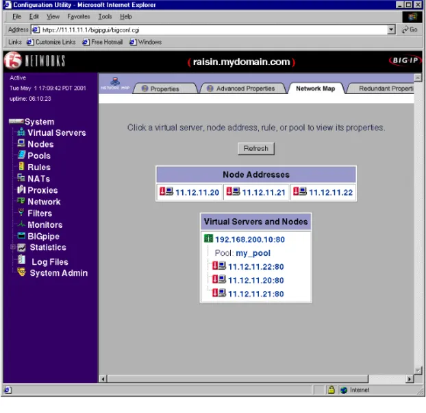
Figure 1.1 shows the Configuration utility as if first appears, displaying the top-level (System) screen with your existing load-balancing configuration. The Configuration utility provides an instant overview of your network as it is currently configured.
Figure 1.1 Configuration utility System screen
The left pane of the screen, referred to as the navigation pane, contains hyper-links to screens for the main configuration objects
BIG-IP Controller Overview
Administrator Guide 1 - 3
Nodes, Pools, Rules, NATs, Proxies, Network, Filters, and Monitors. These screens will appear in the right pane. The left pane of the screen also contains hyper-links to screens for monitoring and system administration (Statistics, Log Files, and System Admin).
A basic configuration
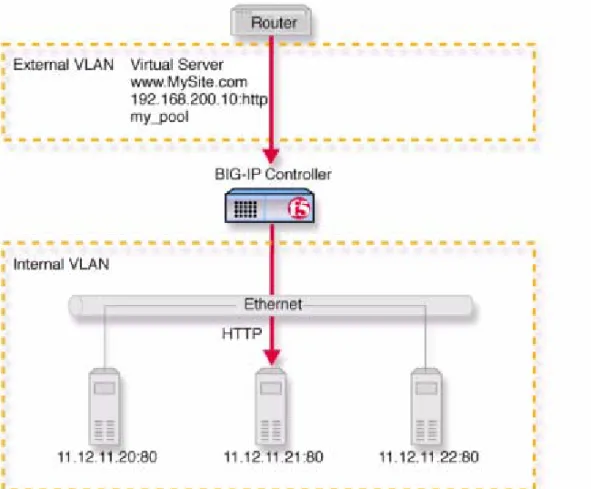
As suggested in the previous section, the System screen shows the objects that are currently configured for the system. These consist of virtual servers, nodes, and a load-balancing pool. What these objects represent is shown in Figure 1.2, a very basic configuration.
Figure 1.2 A basic configuration
In this configuration, the controller sits between a router and an array of content servers, and load balances inbound Internet traffic across those servers.
Insertion of the BIG-IP Controller, with its standard two interfaces, divides the network into anexternal VLAN and an internal VLAN. (However, both VLANs can be on a single IP network, so that inserting the BIG-IP Controller does not require you to change the IP addressing of the network.) The nodes on the external VLAN are routable. The nodes on the internal VLAN, however, are hidden behind the BIG-IP Controller. What will appear in their
BIG-IP Controller Overview
Administrator Guide 1 - 5
place is a user-defined virtual server. It is this virtual server that receives requests and distributes them among the physical servers, which are now members of a load-balancing pool.
The key to load balancing through a virtual server is address translation, and the setting of the BIG-IP Controller address as the default route. By default, the virtual server translates the
destination address of the incoming packet to that of the server it load balances to, making it the source address of the reply packet. The reply packet returns to the BIG-IP Controller as the default route, and the controller translates its source address back to that of the virtual server.
Configuring objects and object properties
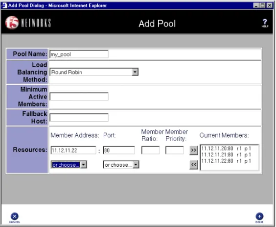
Abstract entities like virtual servers and load balancing pools are called configuration objects, and the options associated with them, like load balancing mode, are calledobject properties. The basic configuration shown in Figure 1.2 contains three types of objects: node, pool, and virtual server. You can create these objects by clicking the object type in the left pane of the Configuration utility. For example, the pool was created by clicking Pools to open the Pools screen, then clicking the Add (+) button to open the Add Pool screen, shown in Figure 1.3.
Figure 1.3 Add Pool screen
The same pool would be configured at the BIG-IP Controller command line using bigpipe as follows:
b pool my_pool { member 11.12.11.210:80 member 11.12.11.21:80 member 11.12.11.22:80 }
BIG-IP Controller Overview
Administrator Guide 1 - 7
Either configuration method results in the entry in Figure 1.4 being placed in the file /config/bigip.conf on the controller. You can also edit this file directly using a text editor like vi or pico.
For a complete description of the configuration objects and properties, refer to the BIG-IP Reference Guide, Chapter 1, Configuring the BIG-IP Controller.
Load balancing modes
Load balancing is the distribution of network traffic across servers that are elements in the load balancing pool. The user may select from a range of load balancing methods, or modes. The simplest mode isround robin, in which servers are addressed in a set order and the next request always goes to the next server in the order. Other load balancing modes include ratio, dynamic ratio, fastest, least connections, observed, and predictive.
• In ratio mode, connections are distributed based on weight attribute values that represent load capacity.
• In dynamic ratio mode, the system is configured to read ratio weights determined by the lowest measured response time from external software.
• In fastest mode, the first server to respond is picked. In least connections mode, the least busy server is picked.
• Observed and predictive modes are combinations of the simpler modes.
For a complete description of the load balancing modes, refer to
Pools in the BIG-IP Reference Guide, Chapter 1, Configuring the BIG-IP Controller.
pool my_pool {
member 11.12.11.20:80 member 11.12.11.21:80 member 11.12.11.22:80 }
BIG-IP Controllers and intranets
So far, discussion has been limited to load balancing incoming traffic to the internal VLAN. The BIG-IP Controller can also load balance outbound traffic across routers or firewalls on the external VLAN. This creates the intranet configuration shown in Figure 1.5, which load balances traffic from intranet clients to local servers, to a local cache, or to the Internet.
BIG-IP Controller Overview
Administrator Guide 1 - 9
This solution utilizes two wildcard virtual servers: Wildcard Virtual Server1, which is HTTP port specific, and Wildcard Virtual Server2, which is not port specific. This way, all non-HTTP requests to addresses not on the intranet are directed to the cache server, which will provide the resources if cached, and otherwise will access them directly from the Internet. All non-HTTP requests not on the intranet will be directed to the Internet.
For detailed information on this solution, refer to Chapter 4, A Simple Intranet Configuration.
Bidirectional load balancing
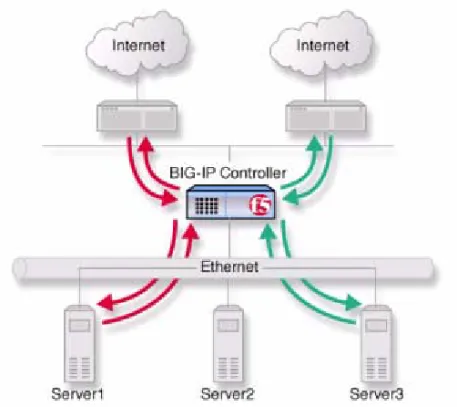
The intranet configuration shown in Figure 1.5 would typically be a part of larger configuration supporting inbound and outbound traffic.
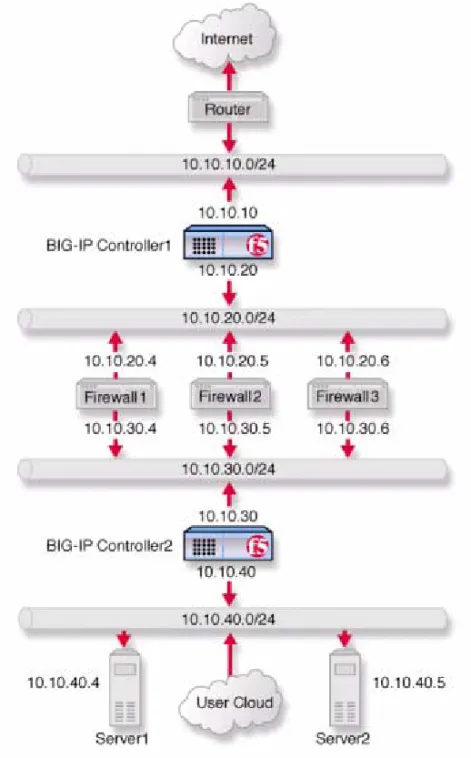
Figure 1.6 shows traffic being load balanced bidirectionally across three firewalls.
BIG-IP Controller Overview
Administrator Guide 1 - 11
This configuration requires two BIG-IP Controllers (or controller redundant pairs), and the creation of three load balancing pools with corresponding virtual servers. A virtual server on the inside BIG-IP Controller (BIG-IP Controller1 in Figure 1.6) load balances incoming requests across the enterprise servers. A virtual server on the outside BIG-IP Controller (BIG-IP Controller2 in Figure 1.6) load balances incoming requests across the external interfaces of the firewalls. A third virtual server on the inside BIG-IP Controller redundant system load balances outbound requests across the internal interfaces of the firewalls. For detailed information on this solution, refer to Chapter 9,
Balancing Two-Way Traffic Across Firewalls.
Cache control
Using cache control features, you can create rules to distribute content among three server pools, an origin server pool, a cache pool for cachable content, and a hot pool. The origin pool members contain all content. The cache pool members contain content that is considered cachable (for example all HTTP and all GIF content). The hot pool members contain cachable content that is considered hot, that is, frequently accessed, as determined by a threshold you set. Once identified, hot content is distributed and load balanced across the pool to maximize processing power when it is hot, and localized to the hot pool when it is cool (less
frequently accessed).
A special cache feature is destination address affinity (also called sticky persistence). This feature directs requests for a certain destination to the same proxy server, regardless of which client the request comes from. This saves the other proxies from having to duplicate the web page in their caches, wasting memory.
For detailed information about cache rules, refer to Rules in the
BIG-IP Reference Guide, Chapter 1, Configuring the BIG-IP Controller.
SSL acceleration
SSL acceleration uses special software with an accelerator card to speed the encryption and decryption of encoded content. This greatly speeds the flow of HTTPS traffic without affecting the flow of non-HTTPS traffic. In addition, using add-on BIG-IP
e-Commerce Controllers, it is possible to create a scalable configuration that can grow with your network.
For detailed information about SSL acceleration, refer to Chapter 8, Configuring an SSL Accelerator.
Content conversion
Content conversion is the on-the-fly switching of URLs to ARLs (Akamai Resource Locators) for web resources that are stored geographically nearby on the Akamai Freeflow NetworkTM. This
greatly speeds download of large, slow-to-load graphics and other types of objects.
For detailed information about content conversion, refer to Chapter 13, Configuring a Content Converter.
VLANs
The internal and external VLANs created on the BIG-IP Controller are by default the separate port-specified VLANs external and internal, with the BIG-IP Controller functioning as an L2 switch. In conformance with IEE802.lq, the BIG-IP Controller supports both port-specified VLAN and tagged VLANs. This adds the efficiency and flexibility of VLAN segmentation to traffic handling between the networks. For example, with VLANs it is no longer necessary to change any IP addresses after inserting a BIG-IP Controller into a single network.
BIG-IP Controller Overview
Administrator Guide 1 - 13
VLAN capability also supports multi-site hosting and allows the BIG-IP Controller to fit into and extend a pre-existing VLAN segmentation, or to serve as a VLAN switch in creating a VLAN segmentation for the wider network.
For detailed information on VLANs, refer to VLANs in the BIG-IP Reference Guide, Chapter 1, Configuring the BIG-IP Controller.
Link aggregation and link failover
Links (individual physical interfaces) on the BIG-IP Controller may be aggregated by software means to form a trunk (an aggregation of links). This link aggregation increases the
bandwidth of the individual links in an additive manner. Thus four fast Ethernet links, if aggregated, create a single 400 Mb/s link. Link aggregation is highly useful with asymmetric loads. Another advantage of link aggregation is link failover. If one link in an trunk goes down, traffic is simply redistributed over the remaining links. Link aggregation conforms to IEEE 802.3ad.
Configuring redundant BIG-IP Controller pairs
BIG-IP Controllers may be configured in redundant pairs, with one unit active and the other in standby mode. This is made convenient by the fact that once one unit has been configured, this
configuration can be copied automatically to the other unit, a process called synchronization. Once the systems have been synchronized, a failure detection system determines whether the active unit is in failure mode and automatically re-directs traffic to standby unit. This process is called failover.
A special feature of redundant pairs is optional state mirroring. When you use the mirroring feature, the standby controller maintains the same state information as the active controller. Transactions such as FTP file transfers continue as though uninterrupted if the standby controller becomes active.
For detailed information about configuring redundant pairs, refer to
Redundant Systems in the BIG-IP Reference Guide, Chapter 1, Configuring the BIG-IP Controller.
Making hidden nodes accessible
To perform load balancing, the BIG-IP Controller hides physical servers behind a virtual server. This prevents them from receiving direct administrative connections or from initiating requests as clients (for example, to download software upgrades.) There are two basic methods for making nodes on the internal VLAN routable to the outside world: forwarding and address translation.
Forwarding
Forwarding is the simple exposure of a node’s IP address to the BIG-IP Controller’s external VLAN so that clients can use it as a standard routable address. There are two types of forwarding, IP forwarding and the forwarding virtual server. IP forwarding
exposes all nodes and all ports on the internal VLAN. You can use the IP filter feature to implement a layer of security.
A forwarding virtual server is like IP forwarding but exposes only selected servers and/or ports.
Address translation
Address translation consists of providing a routable alias that a node can use as its source address when acting as a client. There are two types of address translation: NAT(Network Address Translation) and SNAT (Secure Network Address Translation). NATs are assigned one per node and can be used for both outbound and inbound connections. SNATs may be assigned to multiple nodes and permit only outbound connections, hence the greater security.
BIG-IP Controller Overview
Administrator Guide 1 - 15
For detailed information about address translation, refer to the sections NATs, SNATs,and IP Forwarding inthe BIG-IP Reference Guide, Chapter 1, Configuring the BIG-IP Controller.
Monitoring and administration
The BIG-IP Controller provides two types of monitoring, health monitoring and statistical monitoring.
Health monitors
Health monitoring is the automatic periodic checking of all nodes in load balancing pools to determine if the node is fully functional. A node that fails its health check is marked down and traffic is no longer directed to it. The controller offers ECV (Extended Content Verification) and EAV (Extended Application Verification) monitors covering all the standard protocols. All monitors are user-configurable and a special external monitor is included for user-supplied pingers.
For detailed information about health monitors, refer to the BIG-IP Reference Guide, Chapter 1, Configuring the BIG-IP Controller.
Statistical monitoring
The BIG-IP Controller provides multiple windows into its
operation, including the Configuration utility, bigpipe, and utilities for logging and the display of statistics on specific objects. For example, one utility, Big/stat, allows you monitor statistics specific to virtual servers and nodes, such as the number of current
connections or the number of packets processed since the last reboot. In addition, the BIG-IP Controller has simple network management protocol (SNMP) and management information bases (MIBs) to allow you to configure traps or poll the controller with your standard network management station (NMS).
For detailed information on monitoring and administration features and utilities, refer to Chapter 18, Monitoring and Administration.
2
Basic Web Site and E-Commerce
Configuration
• Working with a basic web site and
e-commerce configuration
• Configuring a basic e-commerce site
• Additional configuration options
Working with a basic web site and e-commerce
configuration
The most common application of the BIG-IP Controller is
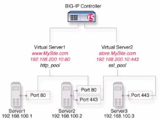
distributing traffic across an array of web servers that host standard web traffic, including e-commerce traffic. Figure 2.1 shows a configuration where a BIG-IP Controller load balances two sites: www.MySite.com and store.MySite.com. The www.MySite.com site provides standard web content, and the store.MySite.com site is the e-commerce site that sells items to www.MySite.com customers.
To set up load balancing for these sites, you need to create two pools that are referenced by two virtual servers, one for each site. Even though the sites are related and they may even share the same IP address, each requires its own virtual server because it uses a different port to support its particular protocol: port 80 for the HTTP traffic going to www.MySite.com, and port 443 for the SSL traffic going to store.MySite.com. Note that this is true even when there are a port 80 and a port 443 on the same physical server, as in the case of Server 2.
Note
Note that in this example, as in all examples in this guide, we use only non-routable IP addresses. In a real topology, the virtual server IP addresses would have to be routable on the Internet.
Chapter 2
2 - 2 BIG-IP® Controller 4.0
Figure 2.1 A basic configuration
Configuring a basic e-commerce site
To configure the e-commerce site, you need to complete the following tasks in order:
• Define the load balancing pools
• Define virtual servers for the inbound traffic
Defining the pools
The first step in a basic configuration is to define the two load balancing pools, one for HTTP, the other for SSL.
To create pools using the Configuration utility 1. In the navigation pane, click Pools.
The Pools screen opens. 2. Click the Add button.
The Add Pool screen opens.
3. In the Add Pool screen, configure the attributes you want to use with the pool. For additional information about configuring a pool, click the Help button.
Configuration Notes
• For this example, you would create an HTTP pool named http_pool and an SSL pool named ssl_pool. • http_pool contains the following members:
192.168.100.1:80 192.168.100.2:80
• ssl_pool contains the following members: 192.168.100.2:443
192.168.100.3:443
To define the pools from the command line
To define a pool from the command line, use the following syntax: b pool <pool_name> {member <member_definition> ... member
<member_definition>}
To create the pools http_pool and ssl_pool from the command line, you would type the following commands:
b pool http_pool { member 192.168.100.1:80 member 192.168.100.2:80 } b pool ssl_pool { member 192.168.100.2:443 member 192.168.100.3:443 }
Chapter 2
2 - 4 BIG-IP® Controller 4.0
Defining the virtual servers
The next step in a basic configuration is to define the virtual servers that reference http_pool and ssl_pool, respectively.
To define the virtual servers using the Configuration utility
1. In the navigation pane, click Virtual Servers. The Virtual Servers screen opens.
2. Click the Add button.
The Add Virtual Server screen opens.
3. In the Add Virtual Server screen, configure the attributes that you want to use with the virtual server. For additional information about configuring a virtual server, click the Help button.
Configuration note
• For this example, create a virtual server
192.168.200.10:80 that uses http_pool and a virtual server 192.168.200.10:443 that uses ssl_pool To define the virtual servers from the command line Use the bigpipe virtual command as shown below. You can use standard service names in place of port numbers. If you have DNS configured, you can also use host names in place of IP addresses. b virtual <virt IP>:<port> use pool <pool_name>
The following command defines a virtual server that maps to pools http_pool and ssl_pool, respectively:
b virtual 192.168.200.10:80 use pool http_pool b virtual 192.168.200.10:443 use pool ssl_pool
Additional configuration options
Whenever a BIG-IP Controller is configured, a number of options are available to the user:
◆ You have the option in all configurations to configure a redundant BIG-IP Controller for fail-over. Refer to Redundant Systems in the BIG-IP Reference Guide, Chapter 1,
Configuring the BIG-IP Controller.
◆ All configurations have health monitoring options. Refer to
Health Monitors in the BIG-IP Reference Guide, Chapter 1, Configuring the BIG-IP Controller.
◆ When you create a pool, there is an option to set up persistence and a choice of load balancing methods. Refer to Pools in the
BIG-IP Reference Guide, Chapter 1, Configuring the BIG-IP Controller.
3
Installing a BIG-IP Controller
without Changing the IP Network
• Installing a BIG-IP Controller without
changing IP networks
Installing a BIG-IP Controller without changing IP
networks
A combination of several features of the BIG-IP Controller allow you to place a controller in a network without changing the existing IP network.
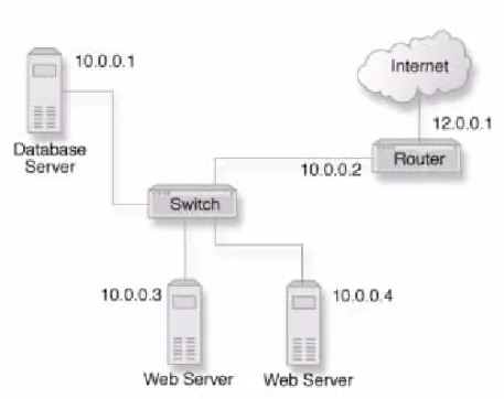
The following figure shows the data center topology before you add the BIG-IP Controller. The data center has one LAN, with one IP network, 10.0.0.0. The data center has one router to the Internet, two web servers, and a back-end database server.
Figure 3.1 Existing data center network structure
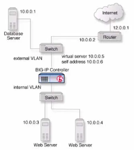
The existing data center structure does not support load balancing or high availability. Figure 3.2 is an example of the data center topology after you add the BIG-IP Controller.
Chapter 3
3 - 2 BIG-IP® Controller 4.0
Figure 3.2 New structure after adding the BIG-IP Controller
Both the internal and external interfaces of the BIG-IP Controller are on the same IP network, 10.0.0.0, but they are effectively on different LANs.
Configuring the controller for the same IP network
To configure the BIG-IP Controller for this solution, you must complete the following tasks:
◆ Remove the self IP addresses from the individual VLANs Remove the self IP addresses from the individual VLANs. Routing is handled by the self IP address you create for the VLAN group.
◆ Create a VLAN group
Create a VLAN group that includes the internal and external VLANs. This enables L2 forwarding.
◆ Create a self IP for the VLAN group
The self IP for the VLAN group provides a route for packets destined for the network.
◆ Create a pool of web servers
Create a pool that contains the web servers that you want to load balance.
◆ Create a virtual server
Create a virtual server that load balances the web servers.
Note
This example assumes that are using the default internal and
external VLAN configuration with self IP addresses on each VLAN that are on the same IP network on which you are installing the controller.
Note
The default route on each content server should be set to the IP address of the router. In this example, you set the default route to
Chapter 3
3 - 4 BIG-IP® Controller 4.0
Removing the self IP addresses from the individual VLANs
Remove the self IP addresses from the individual VLANs. After you create the VLAN group, you will create another self IP address for the VLAN group for routing purposes. The individual VLANs no longer need their own self IP addresses.
WARNING
We recommend that you perform this step from the console. If you are connected from a remote workstation, you will be disconnected when you delete the self IP addresses.
To remove the self IP addresses from the default VLANs using the Configuration utility
1. In the navigation pane, click Network. The VLANs screen opens.
2. In the VLANs screen, click the Self IP Addresses tab. The Self IP Addresses screen opens.
3. Delete the self IP addresses for the external and internal VLANs
To delete self IP addresses from the individual VLANs from the command line
To delete the self IP addresses from the individual VLANs, use the following syntax.
b self <ip addr> delete
Repeat the command to delete each self IP address on the internal and external VLANs.
Creating a VLAN group
Create a VLAN group that includes the internal and external VLANs. Packets received by a VLAN in the VLAN group are copied onto the other VLAN in the group. This allows traffic to pass through the BIG-IP Controller on the same IP network.
Tip
A VLAN group name can be used anywhere a VLAN name can be used.
To create a VLAN group from the Configuration utility 1. In the navigation pane, click Network.
The VLANs screen opens.
2. In the VLANs screen, click the VLAN Groups tab. The VLAN Groups screen opens.
3. In the VLAN Groups screen, click the Add button to add the VLAN group.
Configuration notes
• For this example, the VLAN group name is myvlangroup.
• Make sure the Proxy Forward check box is checked. • Add the internal and external VLANs to the VLAN
group.
To create a VLAN group from the command line
To create the VLAN group myvlangroup from the command line, type the following command:
b vlangroup myvlangroup { vlans add internal external }
Creating a self IP for the VLAN group
The self IP for the VLAN group provides a route for packets destined for the network. With the BIG-IP Controller, the path to
Chapter 3
3 - 6 BIG-IP® Controller 4.0
used in this example, the path to the IP network 10.0.0.0 is actually through more than one VLAN. Since IP routers are designed to have only one physical route to a network, a routing conflict can occur. The self IP address feature on the BIG-IP Controller allows you to resolve the routing conflict by putting a self IP address on the VLAN group.
To create a self IP address for a VLAN group using the Configuration utility
1. In the navigation pane, click Network. The VLANs screen opens.
2. In the VLANs screen, click the Self IP Addresses tab. The Self IP Addresses screen opens.
3. In the Self IP Addresses screen, click the Add button to start the Add Self IP Address wizard.
Configuration notes
• For this example, the self IP address you add for the VLAN group is 10.0.0.6.
• When you choose the VLAN you want to apply the self IP address to, select the VLAN group you created that contains the internal and external VLANs.
To create a self IP address for a VLAN group from the command line
To create a self IP address on the VLAN group, type the following command:
b self 10.0.0.6 vlan myvlangroup netmask 255.255.255.0
Creating the pool of web servers to load balance
After you create the network environment for the BIG-IP
Controller, you can create the pool of web servers you want to load balance.
To create a pool using the Configuration utility 1. In the navigation pane, click Pools.
The Pools screen opens.
2. In the Pools screen, click the Add button to start the Add Pool wizard.
Configuration note
• For this example, the pool contains the web servers 10.0.0.3 and 10.0.0.4.
To create a pool from the command line
To create a pool from the command line, type the following command:
b pool mywebpool { member 10.0.0.3 member 10.0.0.4 }
In this example, you create the pool name mywebpool with the members 10.0.0.3 and 10.0.0.4.
Creating the virtual server to load balance the web servers
After you create the pool of web servers you want to load balance, you can create the virtual server.
To create a virtual server using the Configuration utility 1. In the navigation pane, click Virtual Servers.
The Virtual Servers screen opens.
2. In the Virtual Servers screen, click the Add button to start the Add Virtual Server wizard.
Configuration notes
• For this example, the virtual server address is 10.0.0.5. • Add the pool that contains the web servers 10.0.0.3 and
Chapter 3
3 - 8 BIG-IP® Controller 4.0
To create a virtual server from the command line To create the virtual server for this example from the command line, type the following command:
b virtual 10.0.0.5:80 use pool mywebpool
In this example, mywebpool contains the web servers.
Additional configuration options
Whenever a BIG-IP Controller is configured, a number of options are available to the user:
◆ You have the option in all configurations to configure a redundant BIG-IP Controller for fail-over. Refer to Redundant Systems in the BIG-IP Reference Guide, Chapter 1,
Configuring the BIG-IP Controller.
◆ All configurations have health monitoring options. Refer to
Health Monitors in the BIG-IP Reference Guide, Chapter 1, Configuring the BIG-IP Controller.
When you create a pool, there is an option to set up persistence and a choice of load balancing methods. Refer to Pools in the BIG-IP Reference Guide, Chapter 1, Configuring the BIG-IP Controller.
A Simple Intranet Configuration
A Simple Intranet Configuration
Administrator Guide 4 - 1
Working with a simple intranet configuration
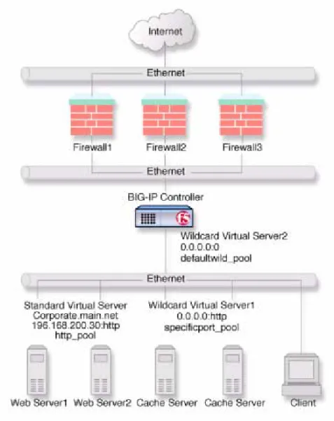
The simple intranet solution described in this chapter is commonly found in a corporate intranet (Figure 4.1). In this scenario, the BIG-IP Controller performs load balancing for several different types of connection requests:
◆ HTTP connections to the company’s intranet web site. The BIG-IP Controller load balances the two web servers that host corporate intranet web site, Corporate.main.net.
◆ HTTP connections to Internet content. These are handled though a pair of cache servers, also load balanced by the BIG-IP Controller.
Figure 4.1 A simple intranet configuration
As Figure 4.1 shows, the non-intranet connections are handled by wildcard virtual servers, that is, servers with the IP address 0.0.0.0 (or * or "any"). The wildcard virtual server handling traffic to the cache servers is port specific, specifying port 80 for HTTP requests. This way all HTTP requests not matching an IP address on the intranet are directed to the cache server. The wildcard virtual server handling non-HTTP requests is a default wildcard
A Simple Intranet Configuration
Administrator Guide 4 - 3
0 (or any or * or "" [blank string]). This makes it a catch-all match for outgoing traffic that does not match any standard virtual server or any port-specific wildcard virtual server.
Creating the simple intranet configuration
To create this configuration, you need to complete the following tasks in order:
• Create load balancing pools
Create pools for the intranet servers you want to load balance and one for the cache server.
• Create virtual servers
Create the virtual servers for each pool and for the non-HTTP requests.
Defining the pools
Define the two load balancing pools, one for the internal servers, the other for the cache servers.
To create pools using the Configuration utility 1. In the navigation pane, click Pools.
The Pools screen opens. 2. Click the Add button.
The Add Pool screen opens.
3. In the Add Pool screen, configure the pool attributes. For additional information about configuring a pool, click the Help button.
Configuration notes
• For this example, you would create two pools: http_pool and specificport_pool.