1. Scope
This technical paper is intended to provide guidance in Data Centre planning and design consideration with main reference to latest technology and largely adopted Data Centres’ deployment strategies. Additionally, it provides information about the different functional elements and design architectures that are shaping the latest Data Centres’ trends.
2. Introduction
Chief Technology Officers (CTO’s), Data Centre Managers and Infrastructure Managers today are daunted with unprecedented challenges to keep up with current business requirements, reduce environmental impact and bring contribution to the bottom line with fewer resources.
Figure 1
Such a scenario requires a multilevel strategic approach supported by high quality skills and knowledge of the various Data Centre components and supporting systems. Enterprises are experiencing enormous growth rates in the volume of data being moved and stored across the network. Foe instance, the deployment of high-density blade servers and storage devices to handle these workloads has resulted in exponential rates of power consumption and heat generation.
Neglecting important aspect of the design can provide the illusion of cost reduction with the long-term result of higher capital expenditure, early obsolescence, and painful network disruption. This paper will discuss the main concept of the Data Centre areas, it will provide a foundation to create a suitable environment able to maximise existing resources and prepare for the implementation of future technologies.
3. The Core Elements in a Data Centre
The main purpose of a data centre is running the applications that handle the core business and operational data of the organization. Internet, video streaming application, such as YouTube™ or Facebook™, together with video-gaming and e-Business applications have expanded rapidly reaching levels of adoption beyond any initial expectation. As a result, the amount of data that is being processed has grown rapidly, also fuelled by a global economy that requires data access at all times from everywhere.
Data Centres are the facilities that will house the equipment in order to secure, store, and exchange data. These drivers have prompt data centres to follow an evolution path that moves from backroom operations to the leading edge of today’s strategic business models.
For these reasons each component of a Data Centre and its supporting systems must be implemented to work flawlessly together, providing the most reliable access to the resources. Most importantly the physical infrastructure has to be able to provide a seamless migration path able to support rapid changes in business requirements and embrace future applications.
The two most significant standards for Data Centre, ISO/ IEC 24764 and TIA/EIA 942, are both characterised by a similar hierarchical nomenclature of the cabling subsystems infrastructure. Fig 2 shows the correlation between the two standard’s hierarchical layouts. They both provide a good foundation to better understand how the different areas of a Data Centre are linked together and interoperate with one another. To avoid any confusion this technical paper will only make reference to ISO/IEC 24764 since this standard has an international scope
Optional Cables
Distributor in acoordance with ISO/IEC 11801
ENI = External Network Interface MD = Main Distributor ZD = Zone Distributor LPD = Local Distribution Point EO = Equipment Outlet
Network Acess Cabling System
Main Distribution Cabling System
Zone Distribution Cabling System
Note: Network access cabling is also used to connect ENI to ZD Office ENI MD ZD EO EO EO EO EO EO EO EO EO EO LDP LDP LDP LDP ZD ENI
Hierarchical structure of generic cabling within a Data Center according to ISO /IEC24764
TIA 942 Data Center Satandard
Main Distribution Area
(Rauters, Backbone, LAN/SAN Switches, PBX, M13 Muxes)
Offices, Operations Center, Support
Rooms
Entrance Room
(Carrier Equipment and Demarcation)
Computer Room Horizontal Distribution Area (LAN/SAN/KVM Switches) Horizontal Distribution Area (LAN/SAN/KVM Switches) Telecom Room
(Office & Operations Centre LAN Switches) Equipment Distribution Area (Rack/Cabinet) Equipment Distribution Area (Rack/Cabinet) Zone Distribution Area Equipment Distribution Area (Rack/Cabinet) Equipment Distribution Area (Rack/Cabinet) Horizontal Distribution Area (LAN/SAN/KVM Switches) Access Providers Access Providers Horizontal Cabling Horizontal Cabling Horizontal Cabling
Horizontal Cabling Horizontal Cabling Horizontal Cabling Backbone Cabling Backbone Cabling Backbone Cabling Horizontal Distribution Area (LAN/SAN/KVM Switches) Fig. 2
Storage (DAS/NAS/SAN), Main Distribution (MD) and Zone
Distribution (ZD) can be seen as the supporting pillars of
any Data Centre architecture. Different network interfaces and applications can be used to create connection between the various elements. For instance Ethernet is adopted in the networking area contained within the Main Distribution, Fibre Channel (FC) and Fibre Channel over Ethernet (FCoE) support communication in the storage area. It is relevant to underline that these applications are not constrained by any physical media, so both fibre and/or copper can be deployed across the different areas. For more information please refer to “DC Applications Reference Guide - Networking & Storage” technical paper.
3.1 Storage Architectures
The digital era has provided individuals and organizations alike with many different possibilities to exchange information. This has created more opportunities to communicate on a global level but also generated a new set of challenges for Data Centres. Storage needs are on a constant increase, IDC estimates storage consumption from enterprise organizations will grow at a compound annual growth rate of 91.8% through 2012.(1)
Storage has become probably the most critical and yet the most vulnerable functional elements of an enterprise’s data centre. For this reason organizations should really take a closer look at how to build and support the infrastructure to access one the most important digital assets – data. Traditional Direct-Attach Storage (DAS) deployments have been preferred in the past for their low cost of ownership. However, since applications have become more complex and the need for flexibility has become more relevant there has been a migration towards more centralized approaches. For this reasons Network Attached Storage (NAS) or Storage Area Networks (SAN) have become more predominant as they also help reducing the amount of hardware and cabling infrastructure associated with it. These innovations are driving faster data transfer speeds such as 10GbE – 40GbE – 100GbE(2) and 2GFC - 4GFC - 8GFC and future 16GFC.(3) Let’s now have a quick look at the different storage devices to better understand the advantages and disadvantages offered by each individual system.
3.2 Direct-Attached Storage (DAS)
DAS is the most basic level of storage and consists of a typical storage device, such as hard disk drive, that comes directly attached to a server or workstation. The main system interfaces used in DAS are the Small Computer Systems Interface (SCSI), serial-attached SCSI (SAS), and Fibre Channel (FC). Although simple to design DAS systems have some substantial downsides:
• Redundant paths are rarely deployed and this may increase risks of downtime • Each DAS require a reserve capacity above
the needed storage space. This is to make sure there is adequate room for data, but it also generates low utilization of storage capacity. For organizations that anticipate rapid data growth, it is important to keep in mind that DAS is limited in its scalability.
3.3 Storage Area Network (SAN)
A SAN system connects storage devices, such as disk arrays and tape library, allowing all clients and applications running over the network to access the storage area. SAN topologies help to increase storage capacity and simplifiy storage
LAN Switch
LAN = Local area network
RAID = Redundant array of independent disks SAN = Storage area network
SAN Switch Servers RAID Disk drive interface card Station or server Disk drives
(1) IDC storage report 2008 (2) GbE Gigabit Ethernet (3) GFC Gigabit Fibre Channel
Fig. 3
administration by the fact that multiple servers can share space on the storage disk.
SAN systems have become largely adopted mainly for their ability to scale as the business requirements evolve. SANs adopt a protocol known as Fibre Channel (FC) although more lately there has been an increased adoption of Fibre Channel over Ethernet (FCoE) using switched fabric topologies.
These protocols are preferred for their ability to provide a high speed throughput with low latency I/O. Fundamentally a SAN help to add more flexibility to the network so that planning and implementation are easier to achieve.
3.4 Network-Attached Storage (NAS)
In essence a NAS topology is constituted by a regular server with minor operating system capabilities. The only purpose is to supply file-based data storage services to other devices on the network. These can be Network File System (NFS), Server Message Block (SMB) or Common Internet File System (CIFS).
The benefit of a NAS over a SAN or DAS is that clients across the network can access the same data simultaneously, whereas SAN or DAS allow only a single client at a time. This makes NAS systems ideal for applications that are shared between multiple clients, such as Web content and e-mail storage. NAS is an ideal choice for organizations looking for a simple and cost-effective way to achieve fast data access for multiple clients.
On the other hand the downside to a NAS is that not all applications will support it because most clustering solutions
are designed to run on a SAN and they require a block-level storage device as opposed to file-based
3.5 Storage systems’ comparison at a glance
Choosing the right storage solution for your business can be a tricky task often driven by personal and individual preconception. In reality there is no one right answer for everyone. Instead, it is important to focus on the specific needs and long-term business goals of your organization. Several key criteria included in Table 1 should be considered and the best chance for success comes with choosing a solution that provides long term investment protection for your organization.
As it was said earlier digital assets will only continue to grow in the future and therefore it is of paramount importance to make sure your storage infrastructure contributes towards a cost-effective expansion and easy scalability.
For this reason it is also important to consider structure cabling solutions that allow for easy migration and expansion of your storage investment without adopting a “rip-and-replace” approach. The main goal of a sound structure cabling solution is to be able to support current applications while providing a seamless pathway transition to future technologies.
Table 1
DAS SAN NAS
Multiple Client access ✕ ✕ ✓
Data sharing ✕ ✓ ✓
Application agnostic ✓ ✓ ✕
Optimised for performance and scalability
✕ ✓ ✓
Support FCoE ✕ ✓ ✕
3.6 Storage and IP convergence
Many data centres today are still operating multiple parallel networks to support their various applications. The detrimental fact is that running multiple networks has a tremendous impact on capital expenditures. So lately there have been several attempts at merging I/O into one consolidated physical infrastructure using Ethernet as the main application. This makes even more sense considering the emergence of 40 Gb/s and 100 Gb/s data rates which makes it clearer that Ethernet is an effective, high-performance I/O consolidation platform now and well into the future.
This has been the main driver for the adoption of FCoE. The main application of FCoE is in data centre storage Departmental Switch Departmental Switch Department 1 Department 1 NAB appliance containing shared departmental data
NAB appliance containing shared departmental data
Main Switch
NAB appliance containing shared organisational data
DAS = Direct-attached storage NAS = Network-attached storage NOS = Network operating system
DAS drives containing NOS and software applications
area networks (SANs) where it offers the advantage of reducing complexity of design and implementation. With FCoE, network (IP) and storage (SAN) data traffic can be consolidated using a single network. This consolidation can:
• reduce the number of network interface cards used to connect storage and IP networks
• reduce the number of switches and attachment cords • reduce power and cooling costs
Table 2 shows a comparison between two hypothetical systems, one that utilises I/O consolidation versus a
traditional system that runs separate application on different networks. It is assumed that in an environment with no I/O consolidation each server presents two adapters, one for Ethernet and one for FC, and that each adapter has two cables.
Table 2 Without I/O consolidation
32 servers FC Ethernet Total
Switches 3 3 6
Adapters 32 32 64
Cables 64 64 128
utilising I/O consolidation
32 servers FC Ethernet Total
Switches none 3 3
Adapters none 32 32
Cables none 64 64
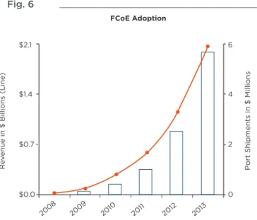
The evident advantages are highlighted by this simple comparison. An I/O system can bring significant saving in terms of equipment, rack space and connections. However, more data traffic is now running through the same cabling infrastructure with the potential risk of creating bottle necks with the consequence of data loss.
Fig 6 illustrates the rapid adoption of FCoE throughout 2013. It is therefore critical to take extra care in the selection of high performance cabling solutions. These have to be capable of withstanding high volumes of data transmission in any given environment, whilst delivering the highest signal performance.
Fig. 6
4 Main Distribution and Zone Distribution
In line with the ISO/IEC 24764 standard the MD houses the main cross connect and the core routers and switches. The ZD can be seen as the main transition point between backbone and horizontal cabling and houses the LAN and SAN switches that connect to servers and storage devices.
Fig. 7
As data centres continue to face the need to expand at a rapid pace, the fundamental concerns related to Main Distribution and Zone Distribution are remaining constant. A properly planned Data Centre infrastructure must be able to deliver three key strategic concepts:
• Agility by providing optimum flexibility
in design and implementation
• Availability of network under the
most stringent conditions
• Efficiency through the highest and most
reliable network performance FCoE Adoption
R
ev
enue in $ Billions (Line
)
P
ort Shipments in $ Millions
$2.1 $1.4 $0.7 2008 2009 2010 2011 2012 2013 $0.0 0 2 4 6 ENI ENI MD ZD Distributor in accordance with ISO/IEC 11801 Network access cabling subsystem Main distribution cabling subsystem Zone distribution cabling subsystem EO EO EO EO EO EO EO EO EO EO LDP LDP LDP LDP ZD
It is advisable that these concepts are taken into
consideration during the planning, design and implementation of the physical infrastructure. It will help to preserve and protect the initial investments and it will guarantee your Data Centre capability to respond to the many changes your business is going to face between now and the next 10 years. As the latest trends of “Virtualization” and “Cloud” start gaining more traction across the industry it is important to create a Data Centre environment that is able to scale its capacity and meet tougher business requirements. An example is brought to evidence by the emerging
technology migration towards 40GbE and 100GbE; these new technologies are needed to support the constant growth of data rate transmission across the various functional elements of modern Data Centres.
Fig 8 illustrates the penetration of 10GbE, 40GbE and 100GbE and the gradual phase-out of legacy technologies. It is interesting to observe that 10GbE is still going to play a major role throughout the next five years alongside with the rapid growth of 40GbE approaching the end of the decade. This underline the importance of building today a network infrastructure that can support the changes in technology that can be foreseen into the near future. Being able to keep on top of these changes is vital part of a company’s ability to retain its business success.
Fig 8
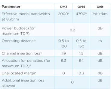
Therefore deploying 10GbE today is more strategic then you may think. In fact a 10GbE network today doesn’t simply have the responsibility to truly support this application, but it also has the greatest task to provide a reliable migration pathway into 40GbE and 100GbE. This is based on the requirements of the latest IEEE 802.3ba standard which presents very stringent performance values to be met, as shown on Table 3.
Table 3
Parameter OM3 OM4 Unit
Effective modal bandwidth at 850nm
2000a 4700b MHz*km
Power budget (for
maximum TDP) 8.2 dB Operating distance 0.5 to 100 0.5 to 150 m
Channel insertion lossc 1.9 1.5 dB
Allocation for penalties (for maximum TDP)d
6.3 64 dB
Unallocated margin 0 0.3 dB
Additional insertion loss
allowed 0
dB
aPer IEC 60793-2-10 b Per TIA-492AAAD
c The channelinsertion loss is calculated using the maximum distances specified
in Table 86-2 and cabled optical fibre attenuation of 3.5 dB/km at 850nm plus an allocation for connection and splice loss given in 86.102.2.1 d Link penalties are used for link bdget calculations. They are not requirements and are not meant to be tested.
e This unallocated margin is not available for use.
So, let’s consider as an example a fibre 10GbE preterminated solution. We want to demonstrate a seamless migration path into 40/100 GbE based on the concept of agility, availability and efficiency. A typical 10GbE installation would look like this:
Fig 9
The main goal of a successful migration strategy is to preserve most of the current investment so that it is still possible to scale the network and accommodate latest technologies. This task needs to be performed by creating minimum disruption and by delivering the performance requirements expected by the standards. One simple way to do this is by swapping only a few components and preserve the rest of the physical infrastructure, which can be achieved in this way:
1G 10G 40G 100G
2007 2008 2009 2010 2011 2012 2013 2014 2015 2016 2017 2018 2019 2020
Server Penetrationof Ethernet Ports by Speed 100 90 80 70 60 50 40 30 20 10 0 % Serv ers LC to MTP* cassette LC to MTP* cassette * MTP is a trademark of USConec
Fig 10
So it is vital that today’s physical infrastructure is built using best in class low-loss components and fibre cable. These must be designed to deliver the highest Bit Error Rate (BER) performance with lowest Insertion Loss (IL) and Return Loss (RL) values. Fig 11 shows an image of a BER eye pattern as a validation of a 10GbE channel performance according to the IEEE 802.3ae standard requirements.
Fig 11
The future of your network is highly dependent on the decision you will make today. This is the time to start thinking more strategic about the physical infrastructure. This way it will be possible to minimise the efforts needed to support the business objectives.
5. Conclusions
We have explored the different functional elements that are the main supporting pillars of modern Data Centres. What comes to light is that successful organizations need to focus on their business requirements and build an IT strategy that looks well into the future.
When it comes to the physical infrastructure elements it is of vital importance to build a network foundation that can support short terms’ needs while keeping truck on the long term objectives.
Successful migration strategies are modelled around the concept of agility, availability and efficiency in order to maximise current investment, minimise risk and provide a robust migration path for the adoption of future technologies. MTP* to MTP* cassette MTP* to MTP* cassette MTP* to MTP* cassette MTP* to MTP* cassette Cabling for 40 Gb/s Cabling for 40 Gb/s
WHITE PAPER
TE Connectivity, TE connectivity (logo), Tyco Electronics, and TE (logo) are trademarks of the TE Connectivity Ltd. family of companies and its licensors.
While TE Connectivity has made every reasonable effort to ensure the accuracy of the information in this document, TE Connectivity does not guarantee that it is error-free, nor does TE Connectivity make any other representation, warranty or guarantee that the information is accurate, correct, reliable or current. TE Connectivity reserves the right to make any adjustments to the information contained herein at any time without notice. TE Connectivity expressly disclaims all implied warranties regarding the information contained herein, including, but not limited to, any implied warranties of merchantability or fitness for a particular purpose. The dimensions in this document are for reference purposes only and are subject to change without notice. Specifications are subject to change without notice. Consult TE Connectivity for the latest dimensions and design specifications.
Contact us:
Please contact us at one of the regional offices shown above.
ADC KRONE products: www.te.com/adckrone AMP NETCONNECT products: www.ampnetconnect.com TE Connectivity: www.te.com
TE Connectivity Enterprise Networks in Europe, Middle East, Africa and India:
North America Greensboro, NC, USA Ph: +1-800-553-0938 Fx: +1-717-986-7406
Latin America Buenos Aires, Argentina Ph: +54-11-4733-2200 Fx: +54-11-4733-2282 Europe Kessel-Lo, Belgium Ph: +32-16-35-1321 Fx: +32-16-35-2188
Mid East & Africa Cergy-Pontoise, France Ph: +33-1-3420-2122 Fx: +33-1-3420-2268
Asia
Hong Kong, China Ph: +852-2735-1628 Fx: +852-2735-1625 Pacific Sydney, Australia Ph: +61-2-9554-2600 Fx: +61-2-9554-2519 Austria Vienna Ph: +43-1-90560-1204 Fx: +43-1-90560-1270 Belgium Kessel-Lo Ph: +32-16-35-1321 Fx: +32-16-35-2188 Bulgaria Sofia Ph: +359-2-971-2152 Fx: +359-2-971-2153 Czech & Slovak Rep. Kurim Ph: +420-541-162-112 Fx: +420-541-162-223 Denmark Glostrup Ph: +45-70-15-52-00 Fx: +45-43-44-14-14 Egypt Cairo Ph: +20-2-2419-2334 Fx: +20-2-2417-7647 Finland Helsinki Ph: +358-95-12-34-20 Fx: +358-95-12-34-250 France Cergy-Pontoise Ph: +33-1-3420-2122 Fx: +33-1-3420-2268 Germany Darmstadt Ph: +49 6151 607-1547 Fx: +49 6151 607-1219 Greece/Cyprus Athens Ph: +30-210-9370-396 Fx: +30-210-9370-655 Hungary Budapest Ph: +36-1-289-1007 Fx: +36-1-289-1010 India Bangalore Ph: +91-80-4011-5000 Fx: +91-80-4011-5030 Italy Collegno (Torino) Ph: +39-011-4012-111 Fx: +39-011-4012-268 Kazakhstan Almaty Ph: +7-327-244-5875 Fx: +7-327-244-5877 Lithuania Vilnius Ph: +370-5-213-1402 Fx: +370-5-213-1403 Netherlands Den Bosch Ph: +31-73-6246-246 Fx: +31-73-6246-958 Norway Nesbru Ph: +47-66-77-88-99 Fx: +47-66-77-88-55 Poland Warsaw Ph: +48-22-4576-700 Fx: +48-22-4576-720 Portugal Evora Ph: +351-961-377-331 Fx: +351-211-454-506 Romania Bucharest Ph: +40-21-311-3479 Fx: +40-21-312-0574 Russia Moscow Ph: +7-495-790-7902 Fx: +7-495-721-1894 Spain Barcelona Ph: +34-93-291-0330 Fx: +34-93-291-0608 Sweden Upplands Väsby Ph: +46-8-5072-5000 Fx: +46-8-5072-5001 South Africa Midrand, Gauteng Ph: +27 11 707 6300 Fx: +27 11 466 3555 Switzerland Steinach Ph: +41-71-447-0-447 Fx: +41-71-447-0-423 Turkey Istanbul Ph: +90-212-281-8181 Fx: +90-212-281-8184 UK Stanmore, Middx Ph: +44-208-420-8140 Fx: +44-208-954-7467 Ukraine Kiev Ph: +380-44-206-2265 Fx: +380-44-206-2264 U.A.E. Dubai Ph: +971-4-321-0201 Fx: +971-4-321-6300