Date : 20/02/2015
Auteur : F. Lamarre (Uniclima), L. Mouradian (CETIAT)
Working Document
Interpretation of SFPint requirement from R 1253/2014
and implementation in EN 13053
1. Aim of the document
Ecodesign requirements for Non Residential Ventilation Units are based on a new parameter SFPint. It is thus necessary to clarify how to measure or calculate it, either for tailor made unit or for compact units. Definitions of R1253/2014 are very general and the draft transitional method for SFPint (last version oct 2013) is based on tailor made units. As this new parameter do not corresponds to any usual performance measured on units and is not relevant for designers, interpretations on its definition is tricky.
Especially the documents from European commission do consider the pressure losses due to the integration effects. We know that the pressure drop of each component of the unit is not the same if it is measured alone or integrated in the casing because of the repartition of the airflow on the components. For compact units, it is impossible to measure pressure drop of components inside the casing. So the French proposal is to follow a deductive approach, based on fans characteristics, because fans are already covered by Eco-design requirement, which is not the case for other components.
2. Reminder : R1253/2014 Definitions (extract)
ANNEX I Definitions
2. Definitions for NRVU, in addition to the definitions in Annex I Part 1:
(1) ‘nominal electric power input (P)’ (expressed in kW) means the effective electric power input of the fan drives, including any motor control equipment, at the nominal external pressure and the nominal airflow;
(2) ‘fan efficiency (ηfan)’ means the static efficiency including motor and drive efficiency of the individual fan(s) in the ventilation unit (reference configuration) determined at nominal air flow and nominal external pressure drop;
(6) ‘nominal flow rate (qnom)’ (expressed in m3/s) means the declared design flow rate of an NRVU at standard air conditions 20 °C and 101 325 Pa, whereby the unit is installed complete (for example, including filters) and according to the manufacturer instructions;
(7)‘nominal external pressure (Δps, ext)’ in (expressed in Pa) means the declared design externalstatic pressure difference at nominal flow rate;
(9) ‘internal pressure drop of ventilation components (Δps,int)’ (expressed in Pa) means the sum of the static pressure drops of a reference configuration of a BVU or an UVU at nominal flow rate;
(10) ‘internal pressure drop of additional non-ventilation components (Δps,add)’ (expressed in Pa) means the remainder of the sum of all internal static pressure drops at nominal flow rate and nominal external pressure after subtraction of the internal pressure drop of ventilation components (Δps,int);
(12) ‘internal specific fan power of ventilation components (SFPint)’ (expressed in W/(m3/s)) is the ratio between the internal pressure drop of ventilation components and the fan efficiency, determined for the reference configuration;
Missing definition : ventilation component…
3. Complement from Draft transitionnal methods (october 2013)
Source :
Possible transitional measurement method (preliminary DRAFT)
DRAFT Commission communication in the framework of the implementation of the
Commission Regulation (EC) No XX/20XX of …… laying down ecodesign requirements for ventilation units, and
Commission Delegated Regulation (EC) No XX/20XX of …… implementing Directive 2010/30/EU of the European Parliament and of the Council with regard to ecodesign requirements for residential ventilation units
(2) On-site market surveillance of large NRVU ventilation units (3)
For large NRVUs, indicatively with a nominal flow rate above 2 m3/s, laboratory testing is not always
possible and is anyway costly for market surveillance purposes. This section describes a technically feasible and less costly method for on-site testing of large NRVUs which is intended to help market surveillance authorities to establish compliance with the ecodesign requirements.
The application of this method, e.g. whether the outcomes are legally binding or not and could be the basis for measures (fines and other penalties) is the responsibility of individual Member States.
Measurements […]
the following parameters shall be established:
1. electric input power, at the mains input terminals to the speed drive (Pfan), in W; 2. incoming (qv, in) air flow rate of the unit (pos. or ), in m³/s;
3. outgoing (qv,out) air flow rates of the unit (pos. ), in m³/s;
4. the static pressure difference (Δpunit) between unit input and unit output (pos. &), in Pa; 5. the static pressure difference (Δpfan) over the fan in- and outlet (pos. &), in Pa;
In case the ventilation unit contains non-ventilation components, e.g. cooling and heating coils, the following additional parameters shall be established:
6. the measured static pressure difference (Δpint’) between fan outlet and the cross-section after the ventilation components, e.g. HRS or filter outlet (pos. &), in Pa;
7. the measured static pressure difference (Δpadd’) between the cross-section after the ventilation components, e.g. HRS or filter outlet, and the unit outlet (pos. &), in Pa;
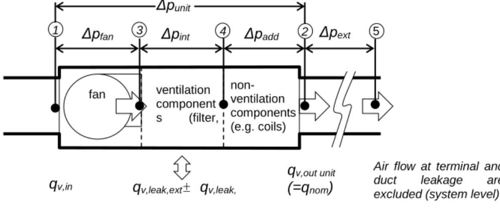
Note that for the product-level regulation the measurement of the static external pressure difference (Δpext) after the fan unit (pos. &), in Pa, the air flow rate at the terminals and the duct leakage are not taken into account.
Figure 1. Illustration supply-side measurements
Calculations
Fan efficiencyηfan
On the basis of measurements 1 (Pfan), 2 (qv, in), 5 (Δpfan) and, alsof for fans with an electric input power smaller than 125 W taking into account the part load compensation compensation factor Cc as
indicated in Commission Regulation (EU) 327/2011, calculate the fan efficiency ηfan as follows ηfan = Cc *(qv, in * Δpfan) / Pfan
where in case of a variable speed drive Cc =1,04 if Pfan ≥ 5 kW and Cc = –0,03 ln(Pfan) + 1,088 if Pfan < 5
kW and in any other case Cc =1.
Internal pressure drop of ventilation components Δpint The value of Δpint , in Pa, is calculated as follows
in case the unit does not contain non-ventilation components Δpint =Δpfan –Δpunit
in case the unit does contain non-ventilation components1 Δpint =Δpint’ *(Δpint’+ Δpadd’+ Δpfan )/Δpunit
Internal specific fan power of ventilation components SFPint The value of SFPint , in W/(m³/s),is calculated as follows for an UVU
SFPint = Δpint / ηfan And for a BVU
SFPint = (Δpint,supply / ηfan,supply) + (Δpint,exhaust / ηfan,exhaust) fan ventilation component s (filter, HRS) non- ventilation components (e.g. coils)
1 Δpfan 3 Δpint 4 Δpadd 2 Δpext 5
Δpunit qv,leak,ext± qv,leak, int qv,in qv,out unit (=qnom)
Air flow at terminal and duct leakage are excluded (system level)
4. French Uniclima proposal 1 for SFPint measurments in EN 13053,
based on fan declaration
The draft of transitory measurements method involves the measurement of ΔPfan inside the casing. However it is not possible for compact unit (no space, measurement not relevant)
It needs to find another method for compact units
The french proposal 1 follow the draft transitonnal methods :
1- For balanced units , SFPint is the sum of supply and exhaust side
SFPint = SFPint sup + SFPint exhaust = (Δpint,supply / ηfan,supply) + (Δpint,exhaust / ηfan,exhaust)
2- Measurement of nominal external pressure (Δps, ext) (7) of the Ventilation Unit for compact system, at the nominal flow rate (qnom) according to ISO 5801, for each air circuit
The unit is at reference configuration without non ventilation components
3- Input data : Fans characterictics
As fans are covered by ecodesign requirements (R327/2011) we are sure that datas are availables and should be reliables (even if declared).
ηfan = Cc *(qv, in * Δpfan) / Pfan can be given by fan manufacturer at qnom
Pfan : electrical consumptionof the fan
4- Calculation
Δps,int=Δpfan –(Δps, ext) with Δps, ext = Δpunit of the draft transitional method
ηfan = Qnom *Δpfan / Pfan
With this method the integration effect of the filter and the heat exchanger is included in Δps,int. But it also includes the integration effect of the fan which penalized the calculation.
Then for supply side and for exhaust side :
𝑆𝐹𝑃𝑖𝑛𝑡,= Δpfan – (𝚫𝐩𝐬, 𝐞𝐱𝐭) 𝜼𝒇𝒂𝒏
Chart 1 : Curve of a fan alone and a reference curve of a NRVU
5. Proposal 2 (Aldes) for SFPint measurments in EN 13053, based on
single components declaration
1- For balanced units , SFPint is the sum of supply and exhaust side
SFPint = SFPint supply + SFPint exhaust
= Δps,int, supply / ηunit supply) + (Δps,int, exhaust / ηunit exhaust)
2- Measurement of
a. nominal external pressure (Δps, ext) (7) of the Ventilation Unit for compact system, at the nominal flow rate (qnom), for each air circuit,
b. electrical power input of the unit Punit (different from P(1) which is for each fan and its drive only)
The unit is at reference configuration without non ventilation components
3- Input data : Ventilation of components characterictics : Δps,int =pcomp
Δpint,exhaust = Δpint,exhaust (heat exchanger)+ Δpint,exhaust (filter on exhaust side) + Δpint,exhaust (casing effect)
Δpint,supply = Δpint, supply (heat exchanger)+ Δpint, supply (filter on supply side) + Δpint, supply (casing effect)
Values are taken from heat exchanger and filter manufacturers (no insertion effect) , or calculated and should be at Qnom
Values for casing effects are not known and there's no existing test method : proposition to neglect them.
4- Calculation – example for supply side
Then for supply side and for exhaust side of BVU :
𝑆𝐹𝑃𝑖𝑛𝑡 =
Σpcomp∗ 𝑃𝑢𝑛𝑖𝑡⁄2 qnom ∗ (𝚫𝐩𝐬, 𝐞𝐱𝐭 + Σpcomp )
Therefore as pint (casing effect) cannot be measured, the integration effect is only included in Punit
6. Discussions
6.1.
Input datas for components alone or integrated in the unit
Pressure drop of filters Usually the pressure loss is measured according to EN 779, at least for nominal airflow of the filter (might not be the same as for; Filter manufacturer will have to give the airflow pressure curve of it filters but it is not obvious, and only for big units (no data for compact units).
The values given by the filter manufacturers are for a homogenous air flow. When the filter is integrated in the unit, the air flows are totally different so the pressure loss will not be the same. The uncertainty of the filters manufacturers values integrated in a product are very high.
Pressure drop of heat exchanger Pressure loss of heat exchanger can be measured according to EN 308. The problem is that the casing of the exchanger is then provided by the lab and do not correspond to the unit casing, as for the filters
Pressure drop of the casing alone Not possible for compact balanced unit (how to do it when you remove the heat exchanger ?)
Integration effect Modification of the air flows due to geometrical reasons and to the airtightness of the product
Pressure/airflow/ efficiency curves of the fan
For a same airflow/pressure point, the rotation speed might be different due to integration effect – slight change on efficiency if the fan is tested alone or in the unit
Pressure/airflow/ efficiency curves of the ventilation section
Fan in the unit : possible only for tailor made units. It is not possible to measure data of fan alone in the casing with removing filters, heat exchanger, … The value given by a pressure probe that would be insert in the casing close to the fan outlet is everything but relevant for compact unit due to the tight environment. Therefore pfan inside the unit can only be
6.2.
Comparison between tailor made units and compact units
We agree to have two methods for tailor made and compact units.
For tailor made units, it is possible to measure sections / sections or to place sensors inside the casing without changing the results.
6.3.
Link with UVU requirements
fan is used clearly for the calculation of SFPint for BVU and UVU with filters.The requirement for UVU without filter is based on vu, but the fan efficiency for such units is not well
defined : is it the efficiency of the fan in the unit or the efficiency of the complete VU ?
6.4.
Conclusion
Regarding market surveillance, manufacturer declaration, reliability of measurement or calculations, both methods present errors and approximations. We have to keep in mind that every data shall be able to be measured in order to prove their reliability and that also units shall not be devalued because the interpretation have direct impact on the market.