Low-Error and High-Throughput Discrete Cosine Transform
(DCT) Design
#1 Mohammad Sadiq Ali #2 K Sumanth
#1Associate Professor ,#2 Student Department of ECE, Sri Venkateswara College Of Engineering And Technology, Chittor.
Abstract
In this paper, by operating the shifting and addition in parallel, an error-compensated adder-tree (ECAT) is proposed to deal with the truncation errors and to achieve low-error and high-throughput discrete cosine transform (DCT) design. Many DCT architectures were proposed on systolic design to reduce the number of multipliers in the systolic design as multipliers consumes high power and occupy less area . Instead of the 12 bits used in previous works, 9-bit distributed arithmetic-precision is chosen for this work so as to meet peak-signal-to-noise-ratio (PSNR) requirements. He proposed 2-D DCT core synthesized by usingXilinx ISE 9.1, and the Xilinx XC2VP30 FPGA can achieve 792 megapixels per second (M-pels/sec) throughput rate.
Index Terms—Distributed arithmetic (DA)-based, error-compensated adder-tree (ECAT), 2-D discrete cosine transform (DCT).
I. Introduction
Discrete cosine transform (DCT) is a widely used tool in image and video compression applications . Recently, the high-throughput DCT designs have been adopted to fit the requirements of real-time applications. The multiplier-based DCTs were presented and implemented in and. To reduce area, ROM-based distributed arithmetic (DA) was applied in DCT cores.
Implemented the DA-based multipliers using ROMs to produce partial products together with adders that accumulated these partial products. In this way, instead of multi-pliers, the DA-based ROM can be applied in a DCT core design to re-duce the area required. In addition, the symmetrical properties of the DCT transform and parallel DA architecture can be used in reducing he ROM size , respectively. Recently, ROM-free DA architectures
were presented employed a bit-level sharing scheme to construct the adder-based butterfly matrix called new DA (NEDA) . Being compressed, the butterfly-adder-matrix in utilized 35 adders and 8 shift-addition elements to replace the ROM.
Based on NEDA architecture, the recursive form and arithmetic logic unit (ALU) were applied in DCT design to reduce area cost . Hence the NEDA architecture is the smallest architecture for DA-based DCT core designs, but speed limitations exist in the operations of serial shifting and addition after the DA-computation. The high-throughput shift-adder-tree (SAT) and adder-tree (AT), those unroll the number of shifting and addition words in parallel for DA-based computation, were introduced respectively. However, a large truncation error occurred. In order to reduce the truncation error effect, several error compensation bias methods have been presented based on statistical analysis of the relationship between partial products and multiplier-multiplicand.
This brief addresses a DA-based DCT core with an error-compensated adder-tree (ECAT). The proposed ECAT operates shifting and addition in parallel by unrolling all the words required to be computed.. Based on low-error ECAT, the DA-precision in this work is chosen to be 9 bits instead of the traditional 12bits so as to achieve the peak-signal-to-noise-ratio (PSNR) requirements. Therefore, the hardware cost is reduced, and the speed is improved using the proposed ECAT.
results are presented in Section IV, and conclusions are drawn in Section V.
II. ECAT Architecture
Fig1 :Q p–bit word shifting and addition operation in parallel
From (2), the shifting and addition computation can be written as follows:
Y =∑Q-1j=0yj.2-j. --- 1.
In general, the shifting and addition computation uses a shift-and-add operator in VLSI implementation in order to reduce hardware cost. However, when the number of the shifting and addition words increases, the computation time will also increase. Therefore, the shift-adder-tree (SAT) presented in operates shifting and addition in parallel by unrolling all the words needed to be computed for high-speed applications. However, a large truncation error occurs in SAT, and an ECAT architecture is proposed in this brief to compensate for the truncation error in high-speed applications.
In Fig. 1, the Q P-bit words operate the shifting and addition in parallel by unrolling all computations. Furthermore, the operation in Fig. 1 can be divided into two parts: the main part (MP) that includes most significant bits (MSBs) and the truncation part (TP) that has least significant bits (LSBs). Then, the shifting and addition output can be expressed as follows:
Y = MP + TP .2- (p-2)---2.
The output will obtain the P-bit MSBs using a rounding operation called post truncation (Post-T), which is used for high-accuracy applications. However, hardware cost increases in the VLSI design.
In general, the TP is usually truncated to reduce hardware costs in parallel shifting and addition operations, known as the direct truncation (Direct-T) method. Thus, a large truncation error occurs due to the neglecting of carry propagation from the TP to MP. Because the products in a multiplier have a relationship between the input multiplier and multiplicand, the compensation methods usually use the correlation of inputs to calculate a fixed or an adaptive compensation bias using simulation or statistical analysis.
Note that the addition elements yqpin the
TP in Fig. 1 (where 1 < q < (Q-1) and (P-q-1 ) < p < (p-1) ) are independent from each other. There-fore, the previous compensation method cannot be applied in this work, and the proposed ECAT is explained as follows
A. Proposed Error-Compensated Scheme
Fig2 : Proposed ECAT architecture of shifting and addition Operators
From Fig. 1, (2) can be approximated as
Y ~~ MP + ϭ. 2 - (P -2) --- 5. Where ϭis the
Compensated bias from the TP to the MP as listed in
Ϭ= Round (TPmajor +TPminor)---- 3;
TPminor
+
+ Qy(Q-1)(P-1) ---4
Where Round() is rounded to the nearest integer. The TP major has more weight than TPminorwhen contributing towards the ϭ. Therefore , the Compensated bias ϭcan be calculated by obtaining TPmajorand estimating TPminor.Let the probability of yqp =1 be 0.5 where 1 < q < (Q-1) and (P-q-1 )
< p < (p-1) . Hence (4) can be expressed as follows:
TPminor= Q+1--- -5.
For a given TP major ,(yj(P -1–j), 0 <
(Q-1)), the Ϭ can be obtained after rounding the sum of (TP major + TP minor) . In order to round the
summation , TPminor can be divided into four parts:
TPminor= K - + ( ) 4k+1
, for Q = 4k
K - + ( )4k+2, for Q = 4k +1
K + ( )4k+3, for Q = 4k +2
K + + ( )4k+4, for Q = 4k +3.6
As K > 1, the TPminor approximates (11)
TPminor =(K -1 ) + , for Q = 4k
(K -1 ) + , for Q = 4k +1
K , for Q = 4k+2
K + , for Q = 4k +37
Hence ,ϭcan be written as three Cases
Case 1 : Q = 0,1,2,3 ϭ= Round(TPmajor)
Case 2 : Q = 4k, 4k+1 (K > 1) ϭ = ( K-1) Round(TPmajor+ 0.5)
Case 3 : Q = 4k+2, 4k+3 (K > 1) ϭ = K + Round(TPmajor
III .Proposed ECAT Architecture
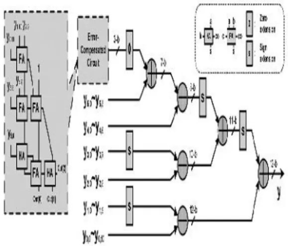
The proposed ECAT architecture is illustrated in Fig. 2 for ( P, Q) =
(12,6) (Case 3 ) where block FA indicates a full– adder cell with three inputs (a,b,c) and two outputs ,a sum(s) and a carry-out (co). Also block HA indicates half-adder cell with two inputs (a and b) and two outputs, a sum (s) and a carry-out (co).
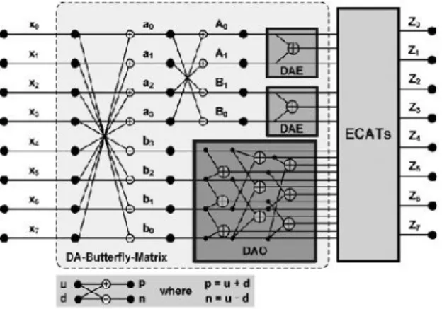
Fig 3: The Architecture of 1-D 8-point DCT
The proposed ECAT has the highest accuracy with a moderate area-delay product. The shift-and-add [7] method has the smallest area, but the overall computation time is equal to 10.8 ( =1.8 x 6 )ns that is the longest. Similarly, the SAT , which truncates the TP and computes in parallel, takes 3.72 ns to complete the computation and uses 406 gates, which is the best area-delay product performance.
1II . Proposed 8x8 2-D DCT Core Design
The 1-D DCT employs the DA-based architecture and the proposed ECAT to achieve a high-speed, small area, and low-error design. The 1-D 8-point DCT can be expressed as follows:
Zn = Kn ) A
transform output ; 0 < n < 7 ; k = for n= 0;
and Kn =1 for other n values . By neglecting the
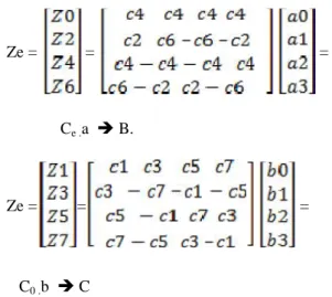
scaling factor ½ , the 1-D 8 –Point DCT in (A) can be divided into even and odd parts; Zeand Zo
as listed in respectively
Ze = = =
Ce .a B.
Ze = = =
C0 .b C
Where ci =cos(i , the even part
Ze can be further decomposed into even and odd
Parts : Zee and Zeo
Zee = = D
Ze0 = = E
For the DA-based computation, the coefficient matrix Co Cee, and Ceo ,are expressed as
9-bit binary fraction numbers. Table III expresses Zee (Z0and Z4 )in the bit level formulation. In Table
III, using given input data A0andA1, the transform
output Zee needs only one adder to compute (A0 +
A1) and two separated ECATs to obtain the results
of Z0and Z4. Similarly, the other transform outputs
Zeo and Z0can be implemented in DA-based forms
using 10 (= 1+9) adders and corresponding ECATs.
The proposed 1-D 8-point DCT architecture can be constructed as illustrated in Fig. 3 using a DA-Butterfly-Matrix, that includes two DA even processing elements (DAEs), a DA odd processing element (DAO) and 12 adders/subtractors, and 8 ECATs (one ECAT for each transform Output Zn ). The eight separated
ECATs work simultaneously, enabling high-speed
applications to be achieved. After the data output from the DA-Butterfly-Matrix is completed, the transform output will be completed during one clock cycle by the proposed ECATs. In contrast, the traditional shift-and-add architecture requires Q clock cycles to complete the transform output z if the DA-precision is Q bits.
IV . Results
Fig 4 : Simulation Result
In a multiplier-based DCT core based on pipeline radix-42 single delay feedback path architecture to achieve high-speed design. The ROM-based DCT core is presented to reduce hardware cost. In a NEDA architecture is presented by using adders to reduce the chip area of DCT core. Nevertheless, a speed limitation for shift-and-add is in NEDA design. In the SAT and AT architectures for DA-based DCTs improve the throughput rate of the NEDA method. A-precision must be chosen as bits to meet the system accuracy with more area overhead. The pro-posed DCT core uses low-error ECAT to achieve a high-speed design, and the DA-precision can be chosen as 9 bits to meet the PSNR requirements for reducing hardware costs.
V .Conclusion
operating the shifting and addition in parallel. Furthermore, the proposed error-compensated circuit alleviates the truncation error in ECAT. In this way, the DA-precision can be chosen as 9 bits instead of 12 bits so as to meet the PSNR requirements. Thus, the proposed DCT core has the highest hardware efficiency than those in previous works for the same PSNR requirements. In summary, the proposed architecture is suitable for high compression rate applications in VLSI designs.
VI .References
[1] Y. Wang, J. Ostermann, and Y. Zhang, Video Processing and Communications, 1st ed. Englewood Cliffs, NJ: Prentice-Hall, 2002.
[2] Y. Chang and C. Wang, “New systolic array implementation of the 2-D discrete cosine transform and its inverse,” IEEE Trans. Circuits Syst. Video Technol., vol. 5, no. 2, pp. 150–157, Apr. 1995.
[3] C. T. Lin, Y. C. Yu, and L. D. Van, “C ost-effective triple-mode reconfigurable pipeline FFT/IFFT/2-D DCT processor,”IEEE Trans. Very Large Scale Integr. Syst., vol. 16, no. 8, pp. 1058– 1071, Aug. 2008.
[4] S. Uramoto, Y. Inoue, A. Takabatake, J. Takeda, Y. Yamashita, H. Yerane, and M. Yoshimoto, “A 100-MHz 2-D discrete cosine trans-form core processor,”IEEE J. Solid-State Circuits, vol. 27, no. 4, pp. 492–499, Apr. 1992.
[5] A. M. Shams, A. Chidanandan, W. Pan, and M. A. Bayoumi, “NEDA: A low-power high-performance DCT architecture,” IEEE Trans. Signal Process., vol. 54, no. 3, pp. 955–964, Mar. 2006.
[6] M. R. M. Rizk and M. Ammar, “Low power small area high performance 2D-DCT architecture,” in Proc. Int. Design Test Workshop, 2007, pp. 120–125.
[7] Y. Chen, X. Cao, Q. Xie, and C. Peng,“An area efficient high performance DCT distributed
architecture for video compression,” in Proc. Int. Conf. Adv. Comm. Technol., 2007, pp. 238–241.
[8] C. Peng, X. Cao, D. Yu, and X.Zhang, “A 250 MHz optimized distributed architecture of 2D 8x8 DCT,” inProc. Int. Conf. ASIC, 2007, pp. 189–192
Authors:
Mohammad Sadiq Ali ,Associate Professor, Department Of Elecronics & Communication Engineering, Sri Venkateswara College Of Engineering & Technology, R.V.S.Nagar, Chittoor.