Enhanced Low Delay AAC Audio Codec
Jochen Issing1, Nikolaus F¨arber1, and Manfred Lutzky11
Fraunhofer IIS, Erlangen, 91058, Germany
Correspondence should be addressed to Jochen Issing ([email protected])
ABSTRACT
The MPEG-4 Enhanced Low Delay AAC (AAC-ELD) codec extends the application area of the Advanced Audio Coding (AAC) family towards high quality conversational services. Through the support of the full audio bandwidth at low delay and low bit rate, it offers excellent support for enhanced VoIP applications. In this paper we provide a brief overview of the AAC-ELD codec and describe how its codec structure can be exploited for IP transport. The overlapping frames and excellent error concealment make it possible to use frame insertion/deletion in order to adjust the playout time to varying network delay. A playout algorithm is proposed which estimates the jitter on the network and adapts the size of the de-jitter buffer in order to minimize buffering delay and late loss. Considering typical network conditions and the same average delay, it is shown that the playout algorithm can reduce the loss rate by more than one magnitude compared to fixed playout.
1. INTRODUCTION
Voice over IP (VoIP) has been widely adopted in the past few years and begins to play a dominant role in todays telephone infrastructure. Besides cost reduc-tion, VoIP has the great potential to significantly im-prove speech quality through advances in compres-sion technology. Current VoIP applications mainly rely on speech codecs with relatively low audio qual-ity, limited to 3.5-7 kHz audio bandwidth. With the
upcoming standardization of low delay perceptual audio codecs, like AAC-ELD, a new quality level can be achieved through full 22 kHz audio bandwidth, multi-channel support, and low content dependency. This new class of audio codecs fulfills the delay and bit rate requirements for conversational services and builds the basis for a new application area, termed
Audio Communication.
network, however, not only the pure source coding parameters are of importance. In addition, packet loss, delay jitter, and abrupt changes in network delay have to be combated. As a matter of fact, the requirements for error concealment and network adaptation rise with higher quality audio connec-tions. Therefore, the integration of the AAC-ELD codec into the transmission framework is studied in this paper.
2. ENHANCED LOW DELAY AAC
In this section of the paper the AAC-ELD codec is introduced with its main features. The provided information is limited to the details needed for the main part of the paper. For further information on AAC-ELD the reader is referred to [3].
2.1. Relation to other AAC Codecs
AAC-ELD combines the strengths of its two main components, MPEG-4 Low Delay AAC (AAC-LD), and Spectral Band Replication (SBR). Whereas MPEG-4 AAC-LD features low encoding/decoding latency, SBR provides high quality audio at very low bit rates. SBR is also used in MPEG-4 High-Efficiency AAC (HE-AAC), one of todays most effi-cient audio codecs.
AAC-ELD is standardized in MPEG since 2008. The technical development of the codec was fi-nalized at the 82nd MPEG meeting in October 2007. The specification document for AAC-ELD is available since January 2008 as ISO/IEC 14496-3:2008/Amd.9. It features two main advantages over AAC-LD: low algorithmic delay of 15 ms with very high audio quality at about 48-64 kbit/s, and a low bit rate with high audio quality at about 24-48 kbit/s and 32 ms algorithmic delay. One audio frame typically covers 10 or 20 ms. Furthermore, it supports super wide band audio bandwidth (14 kHz) at 28 kbit/s and above, scales up to percep-tual transparency, is suitable for speech and music, and provides multi-channel support
2.2. Error Concealment
In low delay communication scenarios it is not pos-sible to retransmit lost packets and reconstruct an error-free bit stream. Instead, the receiver has to be capable to mitigate the effects of packet loss as good as possible by implementingerror concealment tech-niques. In general, error concealment can be seen as
independent from the coding scheme. However, the overlap of audio frames as used in all AAC codecs provides a significant advantage for effective error concealment. Furthermore, it allows to apply low-complexity playout time adjustment as described be-low. Because of the importance to this work, the basic principle is reviewed in this section.
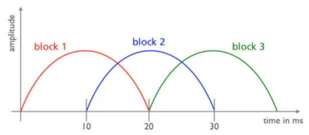
AAC codecs encode audio samples using a certain frame length. AAC-ELD uses a frame length of 480 or 512 sample in the low delay mode at higer bitrates and 960 or 1024 samples in low bit rates mode. Each AAC-ELD frame is windowed, using a delay opti-mized window. In order to reconstruct the audio signal of the current frame, a cross fade with the preceding and following frame is applied. Fig. 1 il-lustrates this basic principle using a simplified sine window.
Fig. 1: Illustration of overlapping AAC frames
In the case where an audio frame is lost, one can mit-igate the loss by exploiting the available information in adjacent frames.
As described above, AAC-ELD consists of two com-ponents, delay optimized AAC and SBR, which re-quire different concealment methods. In [2] and [4] several possible approaches are discussed. Even though spectruminterpolationcan provide the best performance, it can not be used in low delay appli-cations because it causes additional delay. Instead, one has to rely onextrapolation. The error conceal-ment technique employed in this work is based on a combination of prediction, attenuation, and noise substitution in sub bands and can provide good au-dio quality up to a frame loss rate of 10% [4]. 3. ADAPTIVE PLAYOUT
the Realtime Transport Protocol (RTP) [1] is com-monly used. RTP works on top of the User Data-gram Protocol (UDP), which is a connectionless, un-reliable protocol. Therefore, network effects must be detected, measured and compensated in the ap-plication layer. The two main effects that have to be considered are frame loss, where the IP frame is discarded by the network and not conveyed to the receiver andnetwork delay jitter, describing the effect that packets undergo a variable delay while traversing the network. The former is handled by loss detection based on RTP sequence numbers and error concealment as described in the previous sec-tion. This paper focuses on adaptive playout which is an effective method to combat the latter effect, i.e. jitter.
Fig. 2 illustrates the basic principle of adaptive playout and introduces the key variables and perfor-mance criteria. It shows the network delay dn[i] =
tr[i]−ts[i] for a sequence of packets, where iis the packet index andts[i] andtr[i] are the sending time and the reception time respectively. Typically, the sending timests[i] are equidistant at the frame pe-riod T. In the following we assume T = 10 ms as typically used for AAC-ELD. Note that the send-ing time can be recovered at the receiver through the RTP time stamps except for an arbitrary offset, which however is irrelevant for adaptive playout.
Fig. 2: Comparison of fixed vs. adaptive playout
As illustrated in the figure, the network delay is typ-ically not constant but changes over time. The main cause for these changes is the queuing delay in net-work nodes like routers or switches. The queues of these nodes are shared by a variable number of con-current network connections with variable transmis-sion rates. Depending on the current queue length at the time when an audio packet arrives it will un-dergo a variable queuing delay before it is transmit-ted. Because the cross traffic can change almost instantaneously the changes are very dynamic, i.e. in the order of milliseconds. For multiple hops the queuing delays can add up to several 100 ms. An-other reason for delay changes are changes of the routing path. However, these routing events occur on a much longer time scale as shown in [5], i.e. once in several hours or days.
The receiver can compensate this delay jitter by buffering packets in ade-jitter bufferbefore decoding and playout. I.e., after a packet is received it is not decoded and played out immediately but buffered until the playout timetp[i] =tr[i] +db[i], wheredb[i] describes the buffering delay of the packet. Forfixed playout, the playout times are spaced equidistant at the frame periodT, which results in a constant end-to-end delay as illustrated by the solid line in Fig. 2. Any packet arriving before the playout time can be decoded and played out correctly. Packets arriv-ing after the playout time have to be considered as lost and need to be concealed. For clarity, we use the term network lossto describe the packets which are actually lost on the network while the term late loss is used to describe the packets which do arrive but are too late to be played out. The correspond-ing loss rates are denoteden andelrespectively and the total loss rate is e=en+el. Finally we define
db to be theaverage buffering delayof those packets that are actually played out, i.e. neither lost on the network nor late.
Note that the receiver can reduce the late loss by in-creasing the average buffering delay, i.e. by increas-ing the playout time. Selectincreas-ing the right trade-off is up to the receiver implementation and depends on the given delay constraints. Many implementa-tions use a fixed and conservative buffer size, maybe adjustable by the user. This method is simple to im-plement and works for many applications, especially for broadcasting scenarios. For communication
pur-poses, however, it is common practice to improve the trade-off through adaptive playout. The basic idea is to change the playout time adaptively based on estimations of the network jitter as illustrated in the bottom graph of Fig. 2. For example, if the delay and/or jitter increases on the network then the playout time should be increased to reduce late loss. On the other hand, if the delay and/or jitter decreases at a certain point then it does not make sense to maintain a big de-jitter buffer resulting in a long buffering delay. Instead, the buffer should be reduced.
In order to implement adaptive playout two main is-sues have to be addressed. The first issue is the mod-ification of the time scale. Note that the adaptation of the playout time requires to shrink or stretch the audio signal during adaptation. This has to be done with the least possible subjective distortion. Second, the receiver needs to decide when and how fast to in-crease/decrease the jitter buffer size. This task uses network measurements as input and should consider the effect of time scaling on subjective quality. Both issues, Time Modification and Playout Control are addressed in the following two subsections in more detail.
3.1. Time Modification
To adapt the playout to the current buffering re-quirements, the application needs to time stretch or time shrink the audio samples. For stationary time stretching, e.g. to compensate clock drifts be-tween sender and receiver, audio re-sampling can be a good choice. However, the adaptation to changing network conditions is not stationary at all and fast changes in pitch would annoy the listener. There-fore, a different approach is used here, exploiting the principles of AAC and its excellent concealment performance.
Reconsidering section 2.2, it is noted that conceal-ment can already be interpreted as stretching the time of the previously received AAC frame. There-fore, it can be used for increasing the playout time with a very minor modification to the normal opera-tion. Fig. 3 shows the access unit sequence for time stretching in the top line, where an additional “vir-tual” access unit ’C’ is concealed in between AU2 and AU3. In normal concealment operation where the playout time is kept constant, the next access
unit (AU3) would be discarded if it arrives after the concealment operation. In our case, however, it is decoded and played out. As a result, the whole se-quence is four frames long instead of three and the playout time is increased by one frame period T. The resulting effect of this decoding strategy is that the playout time is increased by one frame period for each late loss.
Fig. 3: Time Stretching (top) and Shrinking (bot-tom) using AAC Concealment
On the other hand, if the size of the jitter buffer shall be reduced, single AAC frames are droped, i.e. not forwarded to the decoder. In the bottom line of Fig. 3, one access unit is skipped before decoding. Thus, the actual sequence of access units is no longer 1,2,3,4but1,2,4, shortening the actual sequence of access units by on frame periodT. Although the audio quality of this time stretching and time shrink-ing algorithm may be inferior to more sophisticated approaches such as WSOLA [6], we found that it preserves very decent audio quality. Also note that it is not needed continuously but only at changing network conditions and it does not require any addi-tional processing power because it is built right into the decoder.
3.2. Playout Control
As mentioned above, the playout control is responsi-ble for adjusting the playout time based on network measurements and other information. It is the cen-tral intelligence in the receiver application and has a major impact on the overall performance. We first describe the main receiver structure and then focus on the control algorithm.
3.2.1. Receiver Structure
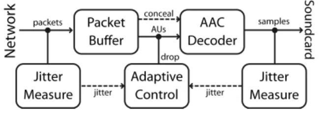
The receiver application includes four main compo-nents as illustrated in Fig. 4. The network inter-face, the packet buffer, the AAC-ELD decoder and the sound card. Network and sound card function-ality is generally provided by the underlying oper-ating system and is therefore not further explained.
The packet buffer stores the received RTP packets, compensates disordering and detects frame loss. In case of frame loss or buffer underrun it tells the de-coder to conceal the current access unit. Otherwise, if a valid access unit is available, it forwards the AU to the AAC-ELD decoder, which decodes the frame and provides its audio samples.
Fig. 4: Receiver Structure
The lower components in Fig. 4 are part of the playout control algorithm and do jitter calculation and playout adaptation. Note that an additional jit-ter calculation from the sound card is indicated in Fig. 4. Sound card jitter has to be considered if the operating system cannot guarantee a sufficient real-time performance for the receiver application. In this case the processing delay for audio decoding and other tasks is not deterministic but varies and can be delayed by several milliseconds. In order to avoid buffer underrun in the sound card, this vari-able processing delay has to be compensated with bigger buffers in the sound card which are filled in bursts during times when sufficient processing power is available. This behavior is very similar to the net-work jitter and treated in an analog way. For spe-cific platforms, operating systems, and network con-ditions we observed that the jitter of the sound card can actually be bigger than the jitter on the network and therefore be the limiting factor. The considera-tion of the sound card jitter is important for software implementations that should run on many platforms at minimum delay. For hardware implementations or in a strict real-time environment there is no need for measuring the sound card jitter and adapt to it dynamically. For simplicity we will ignore the treat-ment of the sound card jitter in the following. 3.2.2. Playout Control Algorithm
The jitter measure module estimates the buffer size, which is needed to absorb the current jitter. This is
accomplish by storing the network delay valuesdn[i] in a delay line (FIFO) containingN=100 values, i.e. 1 second atT=10 ms. The size of the delay line con-trols an important trade-off between fast adaptation and accuracy and was chosen empirically. At the re-ception of packetithe varianceσ2[i] of the network delay is calculated as an estimate over the previous
N samples as σ2[i] = 1 N−1 i X j=i−N+1 (dn[j]−µ)2 (1)
whereµis the estimated mean calculated as
µ= 1 N i X j=i−N+1 dn[j]. (2)
Based on the estimated varianceσ2[i] the minimum buffering time that should be maintained by the re-ceiver is calculated asBmin[i] =Kσ[i], where K is a constant which can be used to control the trade-off between buffering time and late loss. Increasing
Kincreases the buffer size proportional to the esti-mated variance and therefore reduces the probability of late loss. Under the assumption that the network delay is normally distributed, a value ofK= 3 would correspond to the 99% confidence interval, i.e. 99% of the packets should arrive in time. Due to the fact, that network jitter is not normally distributed, an empirical factor ofK= 5 is chosen instead. Based on the resultingBmin[i], which is updated at the reception of each packet, the control of the buffer size is as follows. First, the amount of time which is currently buffered is calculated. If this current buffer time B[i] is greater than the minimum buffer time
Bmin[i] then one audio frame is dropped. Otherwise no dropping is initiated. Furthermore, in order to avoid too fast and therefore annoying playout, the dropping is limited to a certain rate. More specif-ically, dropping is only allowed if more than Dmin packets have been played out continuously without a drop. In our implementation we use a drop rate of 5% i.e. Dmin= 20 based on subjective tests. While the previous paragraph describes when and how the buffer size is reduced, we now describe how the buffer size is increased. Basically, building up
the buffer is accomplished implicitly when reading from the packet buffer. For this purpose, the play-out algorithm follows two simple rules and maintains a so-called expected sequence number, which is in-cremented every time a packet was read out of the packet buffer queue successfully. The first rule is to conceal, if the buffer is empty in which case the expected sequence number is not incremented. As a result, the buffer size is increased by one frame period T for each late loss. The second rule is to
conceal, if the expected sequence number is smaller, than the sequence number of the oldest packet in the queue, which results in loss detection. These two basic rules are sufficient to cover a wide range of network conditions, including delay spikes and long drop outs.
One basic design goal that is implemented by the de-scribed playout control algorithm is to build up the buffer almost instantaneously but reduce the buffer size more slowly. This conservative behavior pro-vides more time to adapt to changing network condi-tions and avoids oscillacondi-tions of continuous buffer in-creases/decreases. Furthermore, in contrast to other playout algorithms, the buffer size is not increased actively without any need but only when late loss actually happens. This avoids unnecessary adapta-tion events that may result from estimaadapta-tion errors in the jitter calculation.
4. NETWORK MEASUREMENTS
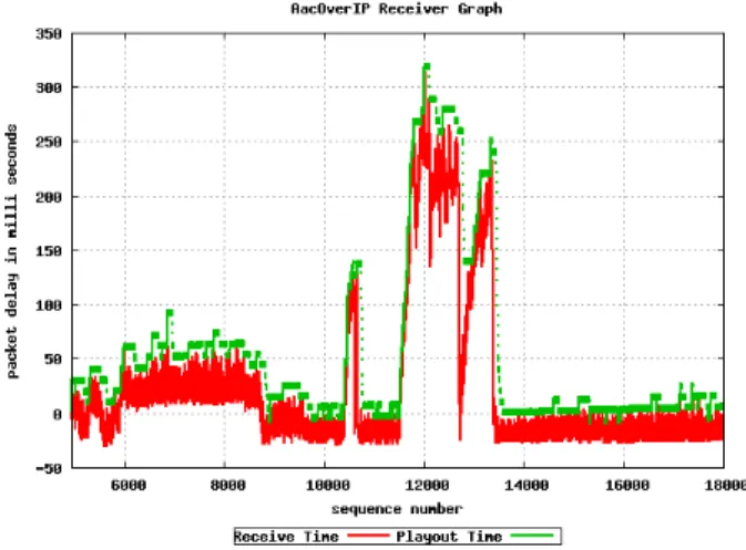
Fig. 5 shows the delay graph of a real network mea-surement, recorded on an intercontinental Internet link between Nuremberg and Berkley over the dura-tion of two minutes.
The lines show the network delaydn[i] and playout delay dp[i] as introduced in Fig. 2. In this mea-surement, jitter varies heavily especially at around sequence number 12000, where the delay increases by more than 200 ms for a duration of about 20 sec-onds. As can be seen, the playout delay follows the network delay very closely and is only slightly above the network delay. Every leap in the playout time stands for either concealment or dropping of one ac-cess unit. According to the frame size of AAC-ELD, every concealment increments the delay by 10 ms, while every drop reduces the delay by 10 ms. To show some more details of the adaption process, Fig. 6 depicts another measurement for a reduced
Fig. 5: Network Trace and Timing Graph
number of packets covering about 10 seconds. At about sequence number 6400 and 6600, two pack-ets are received too late and are concealed by the decoder. The concealment results in a buffer incre-ment of 10 ms, which is indicated by the disconti-nuity in the playout time and the triangle. Since the jitter is reduced again after sequence number 6800, the buffer is reduced by one access unit by the algorithm. Another buffer reduction can also be observed at the very end of the figure.
Fig. 6: Detailed Adaptation Process
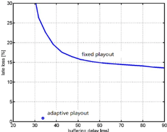
it is obvious that fixed playout results in an un-satisfactory solution. If the playout time is set be-low 150 ms then all packet in the high delay region around sequence number 12000 are lost. However if the playout time is increased above 300 ms in order to completely absorb the jitter then a high buffer-ing delay has to be accepted even for regions that do not require it. Fig. 7 describes this trade-off quantitatively. The solid line depicts the resulting late loss and buffering delay for fixed playout when continuously increasing the playout time. The circle depicts the result for the described adaptive playout algorithm atdb=33 ms andel=1%. As can be seen, fixed playout would result in a late loss of about 23% for the same average buffering delay. Hence, the ef-fective loss rate is reduced by more than a factor of 20 in this example.
Fig. 7: Comparison of Fixed Playout and Adaptive Playout for the network measurement in Fig. 6.
This result of course heavily depends on the par-ticular network measurement. For other interna-tional measurements that we conducted the loss rate can be reduced by a factor in the range of 1.5 -25. Even though not all network situations bene-fit equally from adaptive playout, it is important to note that adaptive playout provides robustness against the more critical situations. Furthermore, the longer a conversation lasts the higher the chance that also a more critical situation will be observed on the network. Therefore, adaptive playout sig-nificantly increases the reliability of the service and
is therefore an essential component for high quality audio communication over IP networks.
5. CONCLUSION
In this paper we describe an adaptive playout algo-rithm to be used with the AAC-ELD audio codec. Adaptive playout is an effective technique to combat network delay variations, also known as jitter. Jitter compensation plays an important role for low delay audio communication over IP networks. Due to the fact, that network jitter is time variant and can heav-ily be impacted by cross traffic, a playout control algorithm is proposed, providing an excellent trade-off between late loss and buffering delay. In order to realize time stretching and shrinking as needed to adapt the playout time we use built in AAC-ELD coding techniques. More specifically, audio frames are dropped/concealed to reduce/increase the buffer size. Though the normal decoding order of access units is changed by these operations, the audio codec is able to handle these discontinuities through the overlap of audio frames and error concealment tech-niques. Finally, the algorithm is tested under real-istic network conditions on intercontinental Internet links. Considering typical network conditions and the same average delay, it is shown that the play-out algorithm can reduce late loss by more than one magnitude compared to fixed playout. Therefore, adaptive playout can significantly increase the re-liability of the service under difficult network con-ditions and is therefore an essential component for high quality audio communication over IP networks. The proposed algorithm achieves this with particu-lar low complexity.
6. REFERENCES
[1] H. Schulzrinne et al., “RFC 3550 - RTP: A Transport Protocol for Real-Time Applica-tion”,
http://www.ietf.org/rfc/rfc3550.txt [2] Andreas Schneider, Kurt Krauss and Andreas
Ehret, “Evaluation of real-time transport pro-tocol configurations using aacPlus”, In 120th AES Convention, Paris, May 20-23, 2006 , Preprint 6789
[3] Markus Schnell et al., “Enhanced MPEG-4 Low Delay AAC - Low Bitrate High Quality
Com-munication”, In 122th AES Convention, Vi-enna, May 5-8, 2007.
[4] Pierre Lauber and Ralph Sperschneider, “Error Concealment for Compressed Digital Audio”,
In 111th AES Convention, New York, Septem-ber 21-24, 2001.
[5] Himabindu Pucha, Ying Zhang, Z. Morley Mao, and Y. Charlie Hu, “Understanding Network Delay Changes Caused by Routing Events”,
In SIGMETRICS’07, San Diego, June 12-16, 2007.
[6] Yi J. Liang, Nikolaus F¨arber, and Bernd Girod, “Adaptive Playout Scheduling and Loss Con-cealment for Voice Communication Over IP Networks”,IEEE Transactions on Multimedia, vol. 5, no. 4, pp. 532 - 543, Dec. 2003.