O R I G I N A L R E S E A R C H
Open Access
Hierarchical distributed control for
decentralized battery energy storage
system based on consensus algorithm
with pinning node
Hanqing Yang, Shihan Li, Qi Li
*and Weirong Chen
Abstract
A decentralized battery energy storage system (DBESS) is used for stabilizing power fluctuation in DC microgrids. Different state of charge (SoC) among various battery energy storage units (BESU) during operation will reduce batteries’service life. A hierarchical distributed control method is proposed in this paper for SoC balancing and power control according to dispatching center requirement in DBESS. A consensus algorithm with pinning node is employed to allocate power among BESUs in the secondary control whereas in the primary control, the local controller of BESU adjusts output power according to the reference power from secondary control. Part of BESUs are selected to be pinning node for accepting command from dispatching center while other BESUs as following nodes which exchange output power and SoC information with the adjacent nodes through communication network. After calculating reference power of each BESU by adopting consensus algorithm, the power sharing in DBESS is achieved according to their respective SoC of BESUs. Meanwhile, the total output power of DBESS follows the varying requirements of dispatching center. The stability of DBESS is also improved because of having no center controller. The feasibility of the proposed control strategy is validated by simulation results.
Keywords:Decentralized battery energy storage system, Hierarchical distributed control, Consensus algorithm, Pinning node
1 Introduction
Compared with the conventional energy sources, renew-able energy sources (RESs) have gained increasing atten-tion due to the advantages of being clean and worldwide distribution [1, 2]. Recently, the concept of microgrid has been proposed for more efficient use of RESs [3, 4]. In particular, DC microgrids have shown to provide sim-pler structure and control than AC microgrids, because of requiring fewer power conversion stages when inte-gration DC sources such as photovoltaic cells, fuel cells and batteries [5].
However, the intermittent and randomness character-istics of RESs cause problems of power quality and sta-bility in microgrids. In order to ensure the security and stability of the system, decentralized battery energy
storage system (DBESS) has become an importance part of microgrid systems [6].
It is well known that the batteries have higher effi-ciency and longer service life when their state of charge (SoC) are maintained at a certain range [7]. Thus, it is important that the SoC of each battery energy storage unit (BESU) is kept similar at all-time within the re-quired range. Therefore, the allocation of total power in DBESS should be controlled to avoid overcharging / over-discharging of any of the BESUs.
Several previous studies have been conducted to achieve SoC balancing. A droop control method com-bining droop coefficient and SoC is proposed in [8] to achieve proportional load power sharing. Reference [9] presents a new droop control method based on voltage scheduling to maintain the SoC of different energy stor-age units balanced by modifying voltstor-age references. To ensure SoC balancing, a gain-scheduling controller
* Correspondence:[email protected]
School of Electrical Engineering, Southwest Jiaotong University, PO Box 610031, Chengdu, China
based on fuzzy logic is designed in [10] by adjusting the droop coefficient.
However, there are several limitations of these methods mentioned above when line resistances are considered, as the batteries will operate at different char-ging/discharging current due to the voltage drops across the line resistances. This will cause the SoC of the BESSs to diverge. Although the centralized control strategy can be used to solve this problem, the required data trans-mission and communication devices introduce potential system instability [11,12].
The hierarchical distributed control needs the autono-mous control units updating their own states by commu-nicating with adjacent nodes to complete complex tasks together. In [13], a distributed multi-agent based algorithm is proposed to realize SoC balancing by means of voltage scheduling. Reference [14] proposes a sliding mode control strategy based on multi-agent system to im-prove the converge speed of the existing SoC balancing strategies. However, these methods are not applicable in energy management as the required power is allocated automatically among batteries according to their respect-ive SoC through communicating with adjacent nodes and cannot receive instructions from dispatching center.
The technique of providing the reference values to only a fraction of agents in the network, known as pin-ning, has been studied in [15, 16]. The pinning-based control can reduce the number of controllers by pinning parts of nodes for a large complex system, which often requires to add controllers to all nodes [17,18].
In this paper, a hierarchical distributed control method is proposed for balancing SoC and controlling power as required from dispatching center in DBESS. A consensus algorithm with pinning node is employed to allocate power among BESUs in the secondary control, whereas
the local controller of BESU in the primary control ad-justs output power according to the reference power from the secondary control.
The rest of the paper is organized as follows. The DBESS is presented in Section 2 whereas Section 3 introduces hierarchical distributed control based on con-sensus algorithm with pinning node. Simulation of dif-ferent operation conditions is developed in Section 4 and finally, Section 5 summarizes the paper and draws the conclusion.
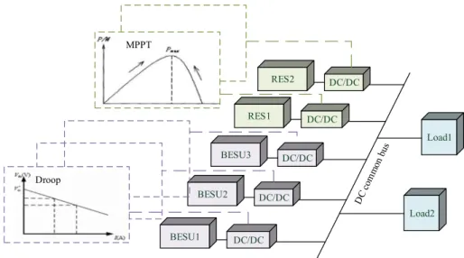
2 Decentralized battery energy storage system A typical DC microgrid configuration with DBESS is presented in Fig.1. In the DC microgrid, RESs can oper-ate at maximum power point tracking mode, supplying power to the common bus. The DBESS is used to stabilize the power fluctuation and maintain the DC bus voltage within a certain range. When the power gener-ated by RESs is less than the load power demand, the DBESS works in the discharge mode, supplying power to the load together with the RESs. When the generated power is greater than the demanded power, the DBESS works in the charging mode to absorb the excess power from the system.
Typically, droop control is employed in the BESU DC/ DC converter for voltage regulation and power sharing. Furthermore, the adaptive droop control based on SoC can dynamically adjust the charge/discharge power of BESU, ensuring all the batteries’ SoC to be consistent after operating for a certain period [8–10].
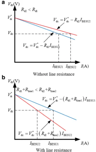
However, there are two limitations by using droop control when considering line resistance. One is the voltage deviation caused by virtual resistance (droop) and line resistance, and the other is the decrease of power sharing accuracy. Adopting adaptive droop
control based on SoC in each BESU, the voltage of the DC common bus can be described as:
Vdc¼Vdc−RdiIBESUi ð1Þ
whereVdcand Vdc *
are the actual and reference voltages of the DC common bus, respectively. Rdi is the virtual
resistance (droop constant) calculated by SoC of thei-th BESU andIBESUiis the output current of thei-th BESU.
When the line resistance is taken into consideration, (1) should be rewritten as:
Vdc¼Vdc−RdiIBESUi−RlineiIBESUi ð2Þ
where Rlinei stands for the line resistance of the i-th
BESU branch.
Taking two BESUs operating in discharging mode as an example, the droop characteristic curves without and with line resistance are shown in Fig. 2aand b, respect-ively. The initial SoC of BESU1 (SoC1) is smaller than SoC of BESU2 (SoC2).
For the case shown in Fig. 2awithout line resistance, it is necessary to satisfy IBESU1<IBESU2(Rd1>Rd2), to
ensure that BESU2 with higher SoC outputs a lager dis-charging current than that of BESU1 with lower SoC. When the line resistances are presented in Fig.2b, in the case ofRd1+Rline1<Rd2+Rline2, the BESU1 with smaller SoC will output more power than BESU2.
Therefore, due to the presence of uncertain line resist-ance, employing the adaptive droop control based on SoC method could potentially lead the BESU with the smallest SoC to a higher discharging rate, resulting in a shorter service life of battery. Therefore, appropriate al-location of total power in DBESS should be achieved to avoid the overcharging/over-discharging of BESUs.
3 Methods
3.1 Hierarchical distributed control
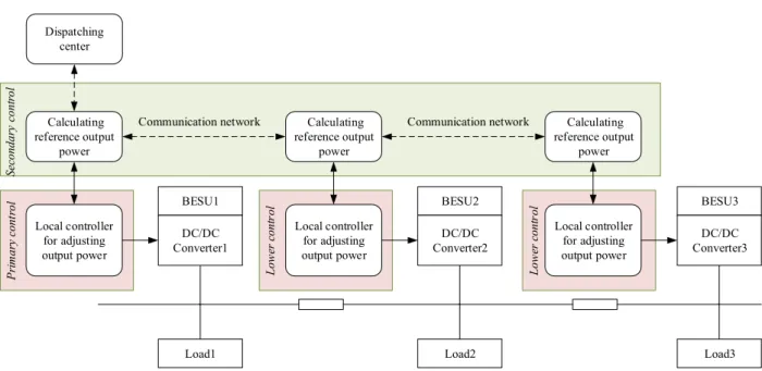
To complete a complex task, it is necessary to divide the task into several simple tasks. So the hierarchical distrib-uted control is employed to divide the whole system into a few autonomous control units to allocate power among BESUs and adjust the output power according to the reference power. The structure of the hierarchical distributed control is shown in Fig. 3, which is divided into three levels including the primary control, the secondary control and the dispatching center.
1) The primary control. It controls the voltage and current of BESU according to the control com-mand sent by the secondary control. Meanwhile, it transmits the collected power, SoC and other physical signals to the secondary control.
2) The secondary control. It sends the calculated control command by exchanging data with adjacent gener-ation units through preset communicgener-ation networks. 3) Dispatching center. By applying the pinning control
to some nodes, the dispatch control of the system can be realized by the coupling relationship be-tween the following nodes and the pinning nodes. In this paper, the primary control and the secondary control of BESU are studied, so that the BESU can automatically control the charge/discharge power based on their respective SoC conditions. At the same time, the part of secondary control units can accept the command from the dispatching center to realize the ability for the whole DBESS to respond to system dispatching.
economic scheduling and hierarchical control. The first-order discrete consensus algorithm is widely used for its advantages of simple convergence condition and fast convergence speed [21].
The BESU can only communicate with its adjacent BESUs. Let xi denotes the state variable of the i-th
BESU, and xi can represent any physical information,
such as voltage, current and SoC. When xiof all BESUs
are the same, the DBESS achieves consensus conver-gence. The discrete consensus algorithm is shown as:
xi½kþ1 ¼
Xm
j¼1
dijxj½ k ð3Þ
where j is an adjacent node of thei-th BESU, dij is the transfer coefficient between the i-th BESU and its adja-cent nodej, andmis the number of BESUs.
However, in a real system, it will take some time in the process of signal conversion and transmission. The time required to transmit the signal from adjacent node jto nodeiis
τij¼τ1þτ2þτ3 ð4Þ
where τ1is the total time for signal sampling and
com-munication processing, τ2 is the time of transmitting
over the communication line, and τ3is the time of
con-verting the received signals by nodei.
The communication among all nodes is discrete in time when using the discrete consensus algorithm and thus, there will be a time interval T between two com-munications. When T is greater than the communica-tion delay τij, the communication delay does not have
any effect on system. In the case ofτijbeing greater than T, the communication delay will impact on the consen-sus algorithm, and the corresponding algorithm expres-sion should be rewritten as:
xi½kþ1 ¼xi½ þk
Xm
j¼1;j≠i
dijxj½k‐1 ð5Þ
Equations (3) and (5) can describe and simulate all the operation conditions whereas (3) stands for normal operation condition with small communication delay and (5) represents condition with lager communication delay.
The transfer coefficient dijcan affect the convergence
and convergence speed of consensus algorithm. When D= [dij] is a random matrix, xi can converge in some
specific conditions [22]. IfDis a double random matrix, xican converge to the average of the system initial value.
In order to improve the reliability of discrete consensus algorithm, the Metropolis method are employed to con-struct a double random matrixDwith non-zero diagonal elements [23]. The Metropolis method is describe as:
dij¼
1 max ni;nj
þ1 j∈Ni
1−X
j∈Ni
1 max ni;nj
þ1 i¼ j
0 others
8 > > > > < > > > > :
ð6Þ
where ni and njare the respective adjacent numbers of nodeiandj, max(ni,nj) stands for the maximum value of
niandnj.
3.3 Consensus control with pinning node
The main principle of the consensus control with pin-ning node is to consider the DBESS shown in Fig.3as a network-connected distributed system. Each BESU con-tains the primary control and the secondary control. The secondary control of BESU which is selected as the pinning node, can receive the dispatching command from the system. The principle of power allocation is that the charge/discharge power of each BESU is the same as the ratio of the power to their respective SoC.
The SoC of BESU needs to be obtained first. For the many published battery SoC detecting methods, the current integration method is employed in this paper to calculate the SoC as [24]:
SoCi¼SoCi−
1
Cei
Z
Ibidt ð7Þ
where Ibi, SoCi*, Cei are the output current, initial SoC
and rated capacity of the battery of the i-th BESU, respectively.
Neglecting the power loss of the DC/DC converter, there is
Pi¼Pini¼UiniIbi ð8Þ
whereUini, Pi,Pini are the output voltage, output power
and input power of the DC/DC converter of the i-th BESU, respectively.
The expression for detecting SoC can be rewritten by combining (7) and (8) as:
SoCi¼SoCi−
1
CeiUin
Z
Pidt ð9Þ
The ratio is then defined in the respective charging and discharging operation states as:
rchari½ ¼k PBESUi½ k SoCi½ k ð10Þ
rdisci½ ¼k PBESUi½ k
SoCi½ k ð
11Þ
where PBESUi[k] and SoCi[k] are the input/output
power and SoC of the i-th BESU, and rchari[k] and rdisci[k] are the charging and discharging ratios of the i-th BESU. PBESUi[k] < 0 stands for charging operation
while PBESUi[k] > 0 for discharging operation. The ratio
of each BESU will tend to be consistent after several iterations by using consensus algorithm. Thus, the purpose of power distribution is achieved.
There are some bases for selecting the BESU to receive power command, e.g. the distance from dispatching cen-ter and reliability of communication network. In this paper, it is assumed that the nearest BESU to dispatch center is BESU1 which is selected to receive the
refer-ence power information from dispatching center
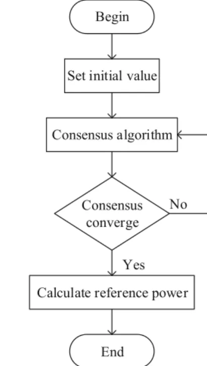
through network communication, and is the pinning node. The remaining BESUs in the DBESS which do not need to have network connection to the dispatching cen-ter are the following node. Figure4shows the flow chart of power allocation in a sampling period.
At the beginning of each sampling period, the initial power values of the pinning node and following node are set as:
PBESU1½ ¼0 Pall
PBESUi½ ¼0 0
ð12Þ
SoC1½ ¼0 SoC1ð Þ0
SoCi½ ¼0 SoCið Þ0
ð13Þ
where Pall is the reference power value from dispatching
center.Pall< 0 stands for charging operation whilePall> 0
represents discharging operation.
Then, the discrete consensus algorithm is used to iterate thePBESUiandSoCias:
PBESUi½kþ1 ¼PBESUi½ þk
Xm
j¼1;j≠i
dijPBESUj½k−1 ð14Þ
SoCi½kþ1 ¼SoCi½ þk
Xm
j¼1;j≠i
dijSoCj½k−1 ð15Þ
After several iterations, (14) and (15) will converge to the average of initial values as:
PBESUi¼k→limþ∞PBESUi½ ¼k
1
n Xn
i¼1
PBESUi½ ¼0 Pall
n ð16Þ
SoCi ¼k→limþ∞SoCi½ ¼k
1
n Xn
i¼1
SoCið Þ0 ð17Þ
Therefore, the charging and discharging ratios of the i-th BESU will also converge to constants as:
rchari¼PBESUiSoCi ¼Pall
Xn
i¼1
SoCið Þ0 =n2 ð18Þ
rdisci¼PBESSi=SoCi ¼Pall=
Xn
i¼1
SoCið Þ0 ð19Þ
Finally, the input power and output power can be calcu-lated by the ratios of charging and discharging operation:
PBESUi¼ r
chari=SoCi charging
rdisciSoCi discharging
ð20Þ
The above equation describes how to obtain the power reference value of each BESU by the consensus control with pinning node. This method is a distributed algo-rithm as each BESU gets its own charge/discharge power reference value according to their own information and information of its adjacent nodes. The SoC of different BESUs can be balanced and the total output power of DBESS follows dispatching requirement.
4 Results and discussion
In order to verify the proposed hierarchical distributed control based on consensus algorithm with pinning node, the simulation model shown in Fig. 5a is estab-lished, which consists of three battery branches with dif-ferent line resistances. The model parameters are shown in Table 1 and the communication network topology is shown in Fig. 5b. However, other communication net-work topologies can also be used as long as they satisfy the requirement of connection. Different network top-ologies only affect the speed of consistency convergence.
In this paper, matrix Dis constructed by (6) and the scheme of self-organization mechanism is designed. In this case, it is assumed that the pinning node is reliable and has been involved all the time. The self-organization mechanism is mainly used to constrain the switching of the following nodes.
Taking BESU2 as an example, when BESU2 needs to be connected in, BESU2 will send incoming packets to BESU1 and BESU3, and then update its own matrix D. After receiving the incoming message, BESU1 and BESU3 broadcast the latest neighbor messages and up-date their own matrix Delements. Their own matrixD are all updated by (6), ensuring that matrix Dis still a double random matrix with non-zero diagonal elements.
According to the self-organization mechanism, the BESU can connect or disconnect their neighbor nodes without affecting the system operation.
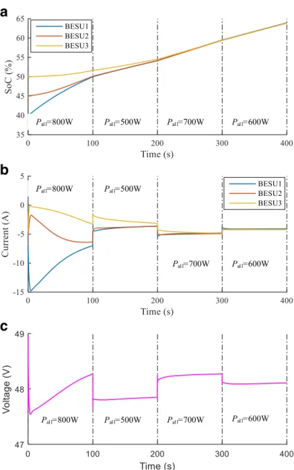
Figure6 shows the simulation results of charging op-eration, and the total power of DBESS is given by dis-patching center and varies with time. The initial SoC of BESU1, BESU2 and BESU3 are 40%, 45%, 50%, respect-ively. Figure 6a and 6b show the SoC and charging current of each BESU, and Fig. 6c presents the average voltage of DBESS.
In 0~ 100 s, the total power of DBESS given by dis-patching center is 800 W. At the beginning of operation, BESU1 has the smallest SoC and absorbs most of the power. At 100 s, the SoC of BESU1 and BESU2 become almost identical and thus, the charging currents also tend to be equal. During the time of 100~ 200 s, the total power of DBESS given by dispatching center is re-duced to 500 W. The charging currents of all BESUs are reduced accordingly. At 200 s the difference of SoC
b
a
Fig. 5Configuration and communication topology of DBESS
Table 1System parameters
Parameters value
Line resistance Rline1(Ω) 0.5 Rline2(Ω) 0.8 Rline3(Ω) 0.9
BESU type Lead-acid battery
Rated voltage (V) 24
Rated capacity (Ah) 5
between BESU1/BESU2 and BESU3 almost disappears. In 200~ 300 s, the total power of DBESS given by dis-patching center is 700 W. During this period, the SoC of these three BESUs is balanced and so as the charging currents. Although the total power changes to 600 W at 300 s, the charging ratios of all three BESUs stay the same. According to Fig. 6c, the voltage is maintained in the range of 48 ± 0.5 V during the operation.
As seen from Fig.6, in the charging operation, the pri-ority is given to the BESU with the lowest SoC to obtain a larger charging current. The proposed control strategy can balance SoC and control output power varying with dispatching center requirements in DBESS.
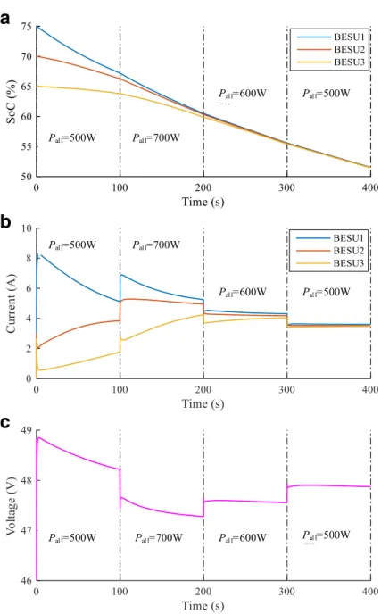
Figure7shows the simulation results of discharging op-eration, and the varying total power of DBESS is given by dispatching center. The initial SoC of BESU1, BESU2 and BESU3 are 75%, 70%, 65%, respectively. Figure 7aand b show the SoC and discharging current of each BESU, and Fig.7cpresents the average voltage of DBESS.
In 0~ 100 s, the total power of DBESS given by dis-patching center is 500 W. At the beginning of operation, BESU1 has the largest SoC and produces most of the output power. At 100 s, the difference of SoC among the BESUs is reduced to be less than 5%. During 100~ 200 s, the total power of DBESS given by dispatching center is increased to 700 W and thus, the discharging currents
a
b
c
of all BESUs are also increased. At 200 s, the SoC differ-ence among the three BESUs is small and therefore, their discharging currents also become similar. In 200~ 300 s, the total power of DBESS given by dispatching center is 600 W whereas it reduces to 500 W at 300 s. During this period, the BESU with the highest SoC al-ways provide more power than the BESU with the smal-lest SoC. Finally, SoC balancing is achieved at 400 s. According to Fig. 7c, the voltage is maintained in the range of 48 ± 1 V during the whole operation.
As seen from Fig. 7, in the discharging operation, al-though the total power demanded varies, the BESU with the lowest SoC always has less discharging current. SoC
balancing and controlling output power according to dispatching center in discharging operation are realized by adopting the proposed control strategy.
5 Conclusions
To address the problems related to the sharing accuracy of the current methods considering the line resistance, a hierarchical distributed control is proposed to realize SOC balancing using consensus algorithm in decentralized bat-tery energy storage system. The proposed control strategy can also change the total output power in DBESS accord-ing to the requirements of dispatchaccord-ing center by pinnaccord-ing partial secondary control units of BESU. The simulation
a
b
c
results in both charging and discharging operation validate the feasibility of the proposed control strategy.
Authors’contributions
HY conceived and designed the study. HY and SL performed the experiments. HY, SL and QL wrote the paper. HY, SL, QL and WC reviewed and edited the manuscript. All authors read and approve the manuscript. The part of establishing DBESS model was supported by National Natural Science Foundation of China (61473238, 51407146), the primary droop control analysis got support of Sichuan Provincial Youth Science and Technology Fund (2015JQ0016), and the part of distributed consensus algorithm was supported by Doctoral Innovation Funds of Southwest Jiaotong University (D-CX201714).
Competing interests
The authors declare that they have no competing interests.
Received: 29 March 2017 Accepted: 2 February 2018
References
1. Li, Q., Chen, W., Liu, Z., et al. (2015). Development of energy management
system based on a power sharing strategy for a fuel
cell-battery-supercapacitor hybrid tramway.J Power Sources, 279(279), 267–280.
2. Xin, H., Lu, Z., Liu, Y., et al. (2014). A center-free control strategy for the
coordination of multiple photovoltaic generators.Smart Grid IEEE Trans, 5(3),
1262–1269.
3. Shen, C. (2013). Wu, et al. multi-stage under frequency load shedding for
islanded microgrid with equivalent inertia constant analysis. Int J Electr
Power Energy Syst, 46(1), 36–39.
4. Guo, W., & Mu, L. (2016). Control principles of micro-source inverters used in
microgrid.Prot Control Mod Power Syst, 1(1), 5.
5. Zhu, X., Liu, J., Liu, Y., Zhou, W., Sun, Z., & Jin, Y. (2014). The study of
micro-grid control strategy contained unbalanced load based on sliding-mode
variable structure.IEEE International Conference on Power System Technology,
pp. 3328–3334.
6. Gu, W., Wu, Z., Bo, R., et al. (2014). Modeling, planning and optimal energy
management of combined cooling, heating and power microgrid: A review.
Int J Electr Power Energy Syst, 54(1), 26–37.
7. Hu, X., Sun, F., & Zou, Y. (2013). Comparison between two model-based
algorithms for li-ion battery SOC estimation in electric vehicles.Simul Model
Pract Theory, 34(4), 1–11.
8. Lu, X., Sun, K., Guerrero, J. M., & Vasquez, J. C. (2012). SoC-based droop
method for distributed energy storage in DC microgrid applications.IEEE
International Symposium on Industrial Electronics, pp.1640–1645.
9. Li, C., Dragicevic, T., Diaz, N. L., Vasquez, J. C., & Guerrero, J. M. (2014).
Voltage scheduling droop control for State-of-Charge balance of distributed
energy storage in DC microgrids.IEEE Energy Conference, pp.1310–1314.
10. Diaz, N. L., Dragicevic, T., Vasquez, J. C., & Guerrero, J. M. (2014).
Fuzzy-logic-based gain-scheduling control for state-of-charge balance of distributed
energy storage systems for DC microgrids.IEEE Applied Power Electronics
Conference and Exposition, pp. 2171–2176.
11. Meng, L., Dragicevic, T., Vasquez, J., Guerrero, J., & Sanseverino, E. R. (2015).
Hierarchical control with virtual resistance optimization for efficiency
enhancement and State-of-Charge balancing in DC microgrids.IEEE First
International Conference on Dc Microgrids, pp. 1–6.
12. Dragicevic, T., Guerrero, J. M., Vasquez, J. C., et al. (2014). Supervisory control
of an adaptive-droop regulated DC microgrid with battery management
capability.Power Electron IEEE Trans, 29(2), 695–706.
13. Li, C., Dragicevic, T., Plaza, M. G., Andrade, F., Vasquez, J. C., & Guerrero, J. M.
(2015). Multiagent based distributed control for state-of-charge balance of
distributed energy storage in DC microgrids.IEEE Conference on Industrial
Electronics Society, pp. 2180–2184.
14. Morstyn, T., Savkin, A., Hredzak, B., & Agelidis, V. (2017). Multi-agent sliding
mode control for state of charge balancing between battery energy storage
systems distributed in a dc microgrid.IEEE Transactions on Smart Grid, PP.
(99), 1–1.
15. Su, H., Rong, Z., Chen, M. Z., Wang, X., Chen, G., & Wang, H. (2013).
Decentralized adaptive pinning control for cluster synchronization of complex
dynamical networks.IEEE Transactions on Systems Man & Cybernetics,43(1),
394–399.
16. Li, X., Wang, X., & Chen, G. (2004). Pinning a complex dynamical network to
its equilibrium.IEEE Trans Circuits Syst Regular Papers, 51(10), 2074–2087.
17. Talebi M, Manaffam S, Jain A K, et al. Intelligent pinning based cooperative
secondary control of distributed generators for microgrid in islanding operation mode. 2016.
18. Liu, W., Gu, W., Sheng, W., Meng, X., Xue, S., & Chen, M. (2016).
Pinning-based distributed cooperative control for autonomous microgrids under
uncertain communication topologies.IEEE Transactions on Power Systems,
31(2), 1320–1329.
19. Chen, C., Zhang, B., Lu, Q., et al. (2015). A consensus algorithm based on
nearest second-order Neighbors’ information. IFAC-PapersOnLine, 48(11),
545–550.
20. Zhang, Z., & Chow, M. Y. (2012). Convergence analysis of the incremental
cost consensus algorithm under different communication network
topologies in a smart grid.Power Syst IEEE Trans, 27(4), 1761–1768.
21. Xu, Y., & Liu, W. (2011). Novel multiagent based load restoration algorithm
for microgrids.IEEE Trans Smart Grid, 2(1), 152–161.
22. Kriegleder, M., Oung, R., & D'Andrea, R. (2013). Asynchronous implementation
of a distributed average consensus algorithm.IEEE International Conference on
Intelligent Robots and Systems, pp. 1836–1841.
23. Guerrero, J. M., Vasquez, J. C., Matas, J., et al. (2011). Hierarchical control of
droop-controlled AC and DC microgrids—A general approach toward
standardization.IEEE Trans Ind Electron, 58(1), 158–172.
24. Bhangu, B. S., Bentley, P., Stone, D. A., et al. (2005). Nonlinear observers for
predicting state-of-charge and state-of-health of lead-acid batteries for