Dagur Ingi Ólafsson
Friction Stir Welding of Aluminum - Copper
School of Engineering
Dissertation for the Degree of Master of Science in Mechanical Engineering Espoo, 26.11.2017
Aalto University, P.O. BOX 11000, 00076 AALTO www.aalto.fi
Abstract of master's thesis
i
Author: Dagur Ingi Ólafsson
Title of thesis: Friction stir welding of aluminum - copper
Degree programme: Mechanical engineering
Major: Mechanical engineering Code IA3027
Thesis supervisor: Prof. Pedro Vilaҫa
Thesis advisor: Prof. Pedro Vilaҫa
Date 26.11.2017 Number of pages: 114 Language English
Abstract
The joining of dissimilar metals is one major challenge for welding technology. There are not many feasible welding techniques able to overcome the different physical properties and deliver a sound structural joint. The application of solid-state welding techniques, although challenging, is one common solution. This work details the development of welding conditions, tools and parameters for the Friction Stir Welding (FSW) of Aluminum-Copper (Al-Cu) butt joint. The application of FSW to these dissimilar joints has proved in the past to be feasible, but several technological and joint performance features, still demand further investigation and development. The motivation and support of this project was a cooperation between Aalto University and Promeco Oy, with ABB Drives Oy as a strategic partner, aiming at providing Promeco Oy with the ability to manufacture high-value dissimilar components, such as, Al-Cu bus bars.
Multiple conventional FSW tools were designed and tested. Parameters were developed to optimize 6 mm thick AA1050-H14/24 – CU-OF-04 butt joints. After preliminary tests, FSW tool was selected for optimization of the process parameters. The tool has ØD3 concave shoulder and ØB threaded taper N/A long probe. The Taguchi method for design of experiments was used for the optimization of three process parameters: travel speed, weld position and offset position of the tool in relation to the joint line between the base materials. The weld was then thoroughly characterized. Tensile, bending and microhardness tests were used to establish the mechanical properties. Optical microscope and scanning electron microscope were used to investigate the microstructure. Joining mechanisms and intermetallic compounds in the weld were investigated using an X-ray diffraction analysis. The electrical resistance of the weld was assessed using a microhmmeter.
The optimized parameters were found to be N/A travel speed; N/A tool plunge and N/A offset into the aluminum. The properties of this optimized weld resulted in 84.8 % Global Efficiency to Tensile Strength (GETS) and 40.8 % Global Efficiency to Bending (GEB) compared to AA1050-H14/24, and 97.2 % electrical conductivity efficiency compared to an ideal bimetallic component made of the same materials with no contact resistance.
To understand the benefits of having an Al bus bar with Cu bolted end, compared with one made of monolithic Al material, a dedicated experimental test setup and protocol was designed and implemented. This experimental test enables to monitor the force relaxation of a pre-loaded bolt joint, under cyclic thermal loading, simulating real operational conditions. The test was applied to both Al base material and Cu base material components. The experimental results show that the force relaxation in the Cu bolted joint was about 50 % lower compared with the Al. Thus, bus bars with Cu ends are more stable and will need less maintenance while in operation than bus bars with Al ends.
An advanced Stationary Shoulder FSW tool was designed, produced and is ready for testing, envisaging a weld joint with improved top surface finishing and good overall engineering performance.
Keywords Friction Stir Welding, Dissimilar Joint, Aluminum, Copper, Tool Design, Stationary Shoulder, Design of Experiments, Bus Bar, Intermetallic Compounds; Metallographic Analysis, Mechanical Properties, Electrical Resistance.
ii
Acknowledgement
To Pedro Vilaҫa, for all your guidance and wisdom given to me while doing this project. To Samuli Laine, Seppo Nurmi, Kim Widell and the engineering support staff, for all the help I received. To my colleagues, Prabilson, Heikki, Gonҫalo, Antti and all the others for making this such a nice workplace. To Jere Lahtinen, for all the lunches.
To my family, for everything. Thank you.
Dagur Ingi Ólafsson Espoo, 26.11.2017
iii
Table of Content
1 Introduction ... 1
1.1 Scope ... 1
1.2 Work Plan and Objectives ... 2
1.3 Organization of the Thesis ... 3
2 State of the Art ... 4
2.1 Introduction ... 4
2.2 Fundamentals of Friction Stir Welding ... 4
2.2.1 Conventional Friction Stir Tools ... 7
2.2.2 Stationary Shoulder Friction Stir Welding ... 9
2.3 Friction Stir Welding of Aluminum-Copper ... 11
2.3.1 General Characterization of Copper and Aluminum ... 12
2.3.2 Material Flow ... 17
2.3.3 Weld Structure ... 18
2.3.4 Intermetallic Compounds ... 19
2.3.5 Defects and Failures ... 22
2.3.6 Influence of Heat Input, Rotational Speed and Travel Speed ... 23
2.3.7 Influence of Tool Offset, Material Positioning and Alloy type ... 27
2.3.8 Effect of Tool Geometry ... 30
2.3.9 Applications ... 32
2.4 Evaluation of Weld Properties ... 33
2.4.1 Tensile Tests ... 34
2.4.2 Bending Tests ... 36
2.4.3 Electrical Resistance Tests ... 37
2.4.4 Hardness Tests ... 38
2.5 Design of Experiments ... 39
2.5.1 Taguchi Method ... 39
2.5.2 Taguchi Method Implementation ... 41
3 Selection and Characterization of Base Materials ... 42
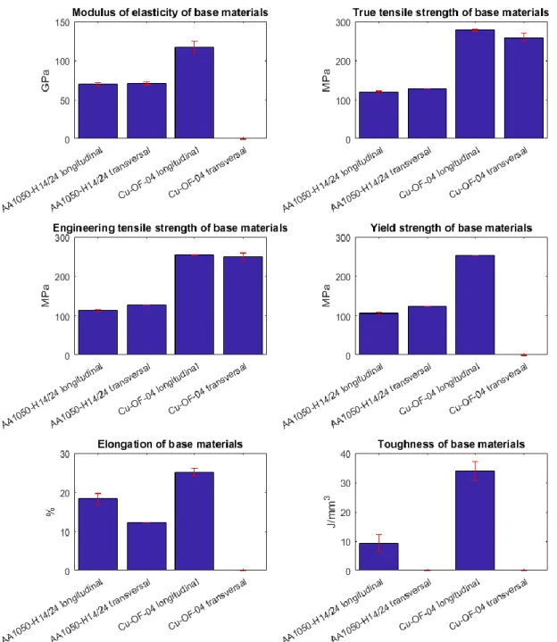
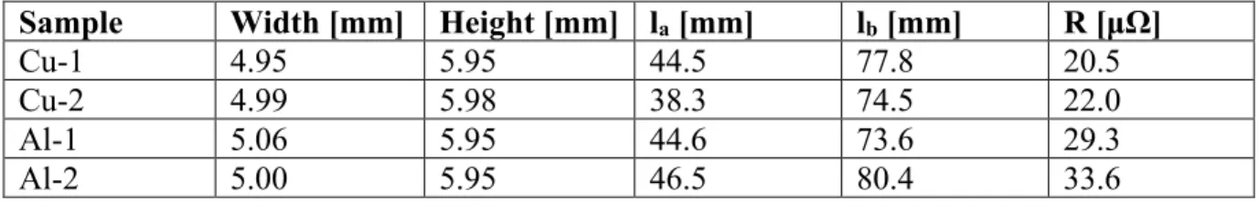
iv 3.2 Material Selection ... 42 3.3 Material Characterization ... 42 3.3.1 Hardness ... 42 3.3.2 Tensile Strength ... 44 3.3.3 Bending Strength ... 46 3.3.4 Electrical Resistivity ... 47 3.3.5 Metallurgical Features ... 49
4 Development of Tooling for FSW ... 51
4.1 Introduction ... 51
4.2 Design and Manufacturing of Conventional FSW Tools ... 51
4.3 Design and Manufacturing of a Stationary Shoulder Tool Module ... 56
4.3.1 Design Specifications and Concept ... 56
4.3.2 FEM Analysis ... 60
4.3.3 Manufacturing ... 62
5 Optimization of FSW Process Parameters ... 63
5.1 Introduction ... 63
5.2 Performance Parameters ... 63
5.3 Establishment of Test Matrix and Process Parameter Levels ... 63
5.4 FSW Procedure ... 65
5.4.1 Clamping system ... 67
5.4.2 Surface Characterization and Specimen Extraction Plan ... 68
5.5 Performance of the DoE Welds ... 71
5.6 Analysis of Variance ... 73
5.7 Calculation of Optimum Performance Parameters ... 77
6 Characterization of Optimized Weld ... 79
6.1 Introduction ... 79 6.2 Temperature Analysis ... 79 6.3 Tensile Properties ... 81 6.4 Bending Properties ... 82 6.5 Electrical Properties ... 83 6.6 Metallurgical Properties ... 84 6.7 Hardness Properties ... 89
v
6.8 Surface Properties ... 89
6.9 Global Analysis of the Results and Translation into Force Control ... 91
7 Relaxation of Clamping Force Experiment ... 93
7.1 Introduction ... 93
7.2 Test Setup ... 93
7.3 Procedure Specification ... 95
7.4 Test Conductance ... 97
7.5 Results ... 99
7.5.1 Lower Peak Temperatures ... 100
7.5.2 Higher Peak Temperatures ... 102
7.6 Analysis of the Results ... 103
8 Summary ... 105
8.1 General Comments ... 105
8.2 Conclusions ... 105
8.3 Future Work ... 107
vi
Abbreviations and Acronyms
AA Aluminium Association (e.g. AA1050)
Al Aluminum
ANOVA Analysis of variance
BM Base material
BOM Bill of materials
Cr Chromium
Cu Copper
DoE Design of experiment
DoF Degree of freedom
Fe Iron
FS Friction stir
FSW Friction stir welding
GEB Global efficiency to bending
GETS Global efficiency to tensile strength
HAZ Heat affected zone
HB Brinell hardness
HV Vickers hardness
IMC Intermetallic compound
Mg Magnesium
Mn Manganese
Pb Lead
PcBN Polycrystalline cubic boron nitrade
RPM Rounds per minute
SEM Scanning electron microscope
Si Silicon
SSFSW Stationary shoulder friction stir welding
Ti Titanium
TMAZ Thermo-mechanically affected zone
WNZ Weld nugget zone
Zn Zinc
1
1
Introduction
As various industries constantly strive to improve their competitiveness, with higher performance products made with efficient processes with low environmental impact. Most of the developments are supported by material optimization demanding advanced solution for processing, namely joining. The research and engineering community works towards meeting these demands willing to transfer the innovative solutions and know-how into industry. Friction Stir Welding (FSW) is a solid-state material joining technology, which opens up possibilities in bimetallic joints of dissimilar materials that is almost impossible to do with conventional fusion welding methods. Welded joints such as aluminum to steel, aluminum to copper and steels to other highly dissimilar iron based components have become a possibility as the process joins materials without melting them. This has opened up new possibilities in the design optimization and manufacturing of various products. E.g. in electrical applications enables to combine cheaper and lighter material, such as aluminum, with copper that has low electrical resistance, with more stable properties and corrosion resistance in a wider temperature range.
1.1 Scope
This thesis details the development of the process conditions for the FSW of aluminum (Al) – copper (Cu) butt joints. It is a cooperation research project between Promeco Oy and Aalto University, named FALCU, which aims at providing Promeco Oy with the know-how for making high-value components based on these joints. The good quality of new high-value products will contribute to increase the competitiveness of Promeco Oy into new international markets. ABB Drives Oy is a strategical partner in this project and a potential customer for the new high-value products.
The solid-state FSW process has shown to be a feasible technological solution to weld dissimilar Al-Cu joints. Fusion welding processes, even advanced technologies such as electron beam welding or laser welding, are not recommended to join Al and Cu, as they tend to form large Intermetallic Compounds (IMCs) [1]. These IMCs are hard and brittle, which critically compromises the quality and applicability of the joints. Moreover, solidification and liquefaction cracking are commonly encountered problems associated with the fusion welding of these materials. FSW is a joining process that uses a non-consumable tool, The combined rotation of the tool while travelling along the joint stirs the visco-plasticized material, activating joining mechanisms between the components without melting and solidifying them. Because the process does not melt the based materials it is very useful for the joining of dissimilar materials with different melting temperatures and other thermal properties, such as, Al and Cu.
The FSW of joints encompassing dissimilar materials is quite sensitive to variations in the clamping, tools and parameters. The FSW of Al-Cu has been previously investigated by other authors, mainly focusing on the influence of basic process parameters, such as, tool travel speed, spindle rotational speed and vertical forging force or penetration depth. The development of key technological issues, like dedicated shoulder and probe dimensions and geometrical features, on the other hand are typically not considered. Advantages of advancements in the technology,
2
such as Stationary Shoulder Friction Stir Welding (SSFSW), for the FSW of Al-Cu have also not been found for this particular application. The work done in this thesis started by developing the welding conditions and tools, based on trial-and-error approach for FSW of Al-Cu components. The best conditions were then selected for base of optimization of key FSW parameters and implementation of a dedicated test setup and protocol to prove the advantages that bimetallic Al electric bus bars, with Cu ends, have over the common monolithic Al bus bars used today.
1.2 Work Plan and Objectives
In order to fulfill the purpose of the thesis the challenges were systematically addressed. A wide theoretical background was established, enabling the familiarization with the materials and FSW process. Existing research on the subject was covered in-depth and built upon in a literature review. Specific Al and Cu materials were selected with the manufacturing of bus bars in mind. The selected Al and Cu were then characterized and tools were designed specifically tailored to the process setup. Based on comprehensive testing of the different manufactured FSW tools with evaluation of the mechanical properties, the best one was selected for optimization of the process parameters. The performance parameters were the efficiency of tensile strength, efficiency on bending and efficiency of electrical conductivity. The optimized conditions were implemented and properties thoroughly evaluated including microscopic analysis and hardness field establishment. A dedicated experiment was designed and conducted to investigate the operational difference between Al bus bars and Al bus bars with Cu connection ends.
The objectives of this work are as follows:
Review and detail the current state of the art for FSW of Al-Cu joints. o Establish a comprehensive literature review.
Characterize the properties of selected base materials.
o Evaluate the tensile strength under static loading, bending strength, electrical resistance, hardness and metallurgical features.
Develop the technological conditions of the process for the selected materials and thicknesses.
o Design, manufacture and test conventional tools for the production of Al-Cu joints.
o Design and manufacture a SSFSW module.
Optimize the FSW process parameters based on design of experiments.
o Apply the best conditions in the production of test specimens for mechanical and metallurgical characterization.
o Monitor the optimized process temperatures using strategically positioned thermocouples.
Evaluate the properties of joints produced with optimized FSW process parameters. Establish the results in terms of efficiency relative to the base materials.
o Investigate and establish the tensile strength, bending strength, electrical properties, hardness and metallurgical features of the joints.
3
Design and conduct an experiment to assess the operational performance of bimetallic bus bars compared to conventional ones made of Al.
o Determine the different clamping force relaxation rates these parts experience while in operation.
1.3 Organization of the Thesis
Following the present introduction, the second chapter is the State of the Art. The fundamentals of FSW, Al and Cu are covered and a comprehensive literature review on the FSW of Al-Cu joints is established. Additionally the technologies for evaluating the quality of welds and the procedures to implement the Design of Experiments (DoE) methodology, used for the process optimization, are detailed.
Chapter 3 describes the selection and characterization of the Al and Cu base materials used in this work. Chapter 4 details the development of tooling for the FSW of Al-Cu joints, focusing on conventional and SSFSW tools. Chapter 5 covers the optimization of the FSW process parameters using DoE and Analysis of Variance (ANOVA) methods.
In chapter 6, the optimized weld condition is characterized and the tensile, bending, electrical, metallurgical and hardness properties established. For the optimized welding condition, the temperatures are monitored using thermocouples. The setup and implementation of the test protocol, of an experiment proving the advantages of bimetallic bus bars, is covered in chapter 7.
Chapter 8 summarizes the work and comprises recommendations for future work.
This document is a public version of the work. Sensitive details have been removed and replaced with “N/A” and important dimensions of designed tools have been replaced with letters. Sensitive information in figures has been blacked out.
4
2
State of the Art
2.1 Introduction
This chapter first covers the fundamentals of FSW, tool design and SSFSW. Then it details issues related to the FSW of Al-Cu with a comprehensive review of other work done in the research area as well as a general characterization of the base materials. The applications of Al-Cu parts is briefly covered. How weld quality is evaluated and the DoE methodology is also discussed.
2.2 Fundamentals of Friction Stir Welding
The process of FSW is one of the most important recent discoveries in the field of joining materials. Invented in 1991 by Wayne Thomas and his colleagues at the welding institute in the United Kingdom [2], it has opened up numerous new possibilities for making high quality welds and avoiding defects that are common in more conventional fusion welding techniques.
FSW is a solid-state welding process; it joins materials without melting them. The process welds by rotating a non-consumable tool inside the materials to be welded in order to soften them locally using heat generated by friction and plastic deformation. Once softened, the joint surfaces are stirred and joined, still in their solid state, as the materials do not reach their melting temperatures. This increases the weld quality compared to fusion welding as it avoids the many problems associated with fusion welding such as changes in volume, gas solubility, distortion and residual stress [3].
FSW has numerous other benefits unrelated to the quality of welds. It has been shown to nearly reduce the emission of hazardous fumes to zero as well as to reduce the energy used during welding, therefore having less environmental impact than other more traditional welding techniques. The process can be used in all orientations as gravity has negligible impact during FSW. Due to high forces the process is typically fully mechanized which increases the equipment cost while lowering the skill requirements and cost of operators [3].
5
Traditionally, the FSW tool consists of a shoulder, which sits on the surfaces of the materials being welded, and a smaller pin, usually called probe, that almost fully penetrates the materials. While the tool rotates and travels along the joint surfaces, the shoulder keeps the softened materials down, preventing them from escaping. When the materials are softened, deformed and plasticized they generate the majority of the heat input of the process. The friction between the rotating shoulder and the welded material also provides additional heat input into the weld. Inside the materials, the probe breaks up the original surfaces of the joint and mixes them together. In order to achieve a fully penetrated joint the probe must penetrate to at least 0.5 mm from the bottom surface of the materials. The probe is commonly threaded in order to provide a downward push to the material, which thwarts pores and voids from forming [3]. The design of
the tool has been intensely researched and in some areas, conventional tools with flat shoulders and threaded pins have given way to other innovative shapes such as conical and scrolled shoulders and taper and plain probes [5].
It is possible to divide the FSW process into three parts: The plunge phase, the weld phase and the termination phase. During the plunge phase, the tool is plunged downwards, if the base materials are parallel to the ground, into the materials with a specific speed and force while rotating. Due to friction and pressure, the material is displaced and deforms around the pin as it is entering the base materials. The pin is usually plunged into the interface of the materials to be joined but sometimes, especially in FSW of dissimilar materials; it is plunged into either material at the side of the interface line and then moved towards it. During the weld phase, the rotating tool is moved along the joint. Plastic deformation and friction generate heat in order to soften the materials so it may flow around the pin. Once the tool has reached the end of the joint line, it is stopped and the tool is moved up out of the materials. This leaves a keyhole in the material at the end of the weld that can make it unfit for use. This is usually solved by using a run-off tab where the tool is withdrawn which is then cut off in order to avoid leaving the welded materials with a keyhole [3].
As the forces acting during the process are high this sets great requirements on the clamping system that keeps the materials fixed and prevents them from sliding, bending or separating. The backing plate has be very planar without any variations greater than 0.1 mm or otherwise the FSW machine has to be able to compensate for it in order to keep the constant bond of the pin. The most straightforward way to clamp sheets is using clamping claws. They provide a high clamping force while taking a long time to set up. In serial production, automatic clamping systems made of hydraulic or pneumatic fixtures are often used although they are quite expensive so their use can only be justified in industrial production situations [3].
In FSW, there exist two different material flow paths. These flow paths have an origin to the left and right of the movement of the tool. On one side, where the tangent of the tool’s rotation is in the same direction as the tool’s movement, the material is forced to flow forward along the tool. This side is called the advancing side, see Figure 1. The material on the other side is forced backwards along the tool and is thus called the retreating side [3]. This phenomena causes the
6
weld to be asymmetrical and becomes increasingly important in Friction Stir (FS) butt-welding of dissimilar materials.
FSW joints consist of four different regions; base material (BM), heat affected zone (HAZ), thermomechanically affected zone (TMAZ) and the weld nugget zone (WNZ), also called the stirred zone. The base material is remote from the weld, is unaffected by the process and has not been deformed. The heat affected zone is closer to the center of the weld and the zone has been through a change in microstructure and/or mechanical properties due to a thermal cycle which it has experienced. The thermomechanically-affected zone lies even closer to the weld center and has been both plastically deformed by the FSW tool and affected by the thermal cycle it has experienced. The weld nugget zone has, just like TMAZ been plastically deformed and heat affected but the difference between the two zones is that the material in the weld nugget zone has recrystallized [6].
Figure 2 - A cross section of a FSW weld, showing the four different regions [7]
Many joint designs and geometries are possible to make with FSW. For FSW to be able to weld a certain joint design it is crucial to have: enough area for the shoulder path, the possibility to contain the softened weld material, enough clamping force to keep the welded materials from moving and to dissipate the heat of the process with a good enough heat sink. Common joint configurations like butt joints, lap joint, 90° joints and T-joints can all be welded using FSW. The joints themselves often need to be prepared to minimize contaminants and oxide layers that can result in poor fatigue strength, volumetric defects and low ductility locally [3]. The oxide
layer can cause bonding problems and weak points within the weld. It is important that the rotating probe is able to break the layer up so that is not continuous inside the weld, which can drastically lower the weld’s strength.
7
2.2.1 Conventional Friction Stir Tools
As stated before, a FSW tool traditionally consists of a round shoulder and a threaded cylindrical probe. The probe moves the softened material around and mixes it to form the joint while the shoulder keeps the material from escaping. During the process, the FSW tool is under severe stress and high temperatures, especially when welding hard materials such as Cu and steel. The geometry of the tool effects the heat generation rate, torque, traverse force and the thermomechanical environment that the tool and base materials experience. It is not only important to select a tool with geometry suitable for the materials and joint design but the tool needs to be manufactured from suitable materials and processed so that it can withstand the forces and the stress it experiences during the weld. Otherwise, the tool quickly wears out and fails. Most tools for welding Al are made out of steel. Tool steel, high-speed steel and other hardened steels are a popular choice and are also used for welding some dissimilar materials such as Al to magnesium and Al to Cu. For welding other, more demanding materials, tool materials like Polycrystalline cubic Boron Nitride (PcBN) and tungsten-based ones are a good choice. [5].
Figure 3 - Shoulder geometries [8]
The geometry of the FSW tool is a very important factor in the welding process, both the shoulder and pin geometry. The shoulder generates most of the frictional heat during FSW and the material flow is largely governed by the shoulders grip on the plasticized materials. The main influencing parts of the shoulder is the contact area between the shoulder and the welded material. The three most commonly used shoulder end surfaces are either flat, concave or convex. The simplest end surface is featureless but features such as scrolls and grooves are commonly used to influence and improve the material flow properties and the heat generated
8
during welding. Scrolled shoulders either, depending on the tool rotation, move material into or out from the weld center as the geometry guides the material into certain flow paths. Flat shoulders can pose a problem, especially when high forging loads are used as the flat surface does not efficiently keep the flowing material constrained under the shoulder, which can result in weld defects when the material escapes the weld. Concave shoulders do not have this problem. They are operated using a small tool tilt of 2-4°. When the tool moves inside the materials with an angle, the front end of the shoulder does not push through the material but is positioned a small distance above it. The surface material gathers inside the concave shoulder and is then deposited back into the weld from under the back end of the shoulder [8].
Probe geometries can also be quite variable; cylindrical threaded, triangular, threaded taper, square and flat cylindrical probes are commonly used in FSW. Flutes are also a common feature on probes, but threads and flutes increase the downward force from the pin onto the material
[5]. Taper geometries lower the force acting on the bottom of the probe, thus extending the life
of the tool. Flutes and scrolls on the probe increase turbulent flow in the weld, which promotes better mixing and the breakup of the oxides of the materials. This forces new chemically active surfaces of the two materials to form, which promotes the bonding of the materials.
Figure 4 - Probe geometries [8]
As during welding the FSW tool, especially the probe, is under high stresses and forces while it rotates, which often results in heavy wearing of the tool. The tool can also plastically deform under elevated temperatures as the yield strength lowers. Therefore, tools are often liquid cooled
9
in order to keep the working temperature of the tool low to avoid plastic deformation. The tool wear mechanism during FSW is mostly diffusion and abrasion. Certain techniques have been used to reduce tool wear in FSW of dissimilar materials. In lap-welds, the softer material can be placed on top of the harder material so that the probe is mostly immersed in the softer one. This reduces the stress and forces on the probe resulting in less tool wear. Similar technique is often used when welding butt joints. There the tool is often offset towards the softer material, which reduces the contact with the harder material; reducing tool stress and tool wear [9].
2.2.2 Stationary Shoulder Friction Stir Welding
Stationary Shoulder Friction Stir Welding (SSFSW) is a variant technique of traditional FSW. As the name suggest the difference in technique is that in SSFSW the shoulder does not rotate. It was originally developed to weld titanium-based alloys, due to titanium’s low thermal conductivity. SSFSW is also used for welding most other materials commonly welded by FSW as the variant offers numerous benefits over the traditional method [10]:
Improved surface quality Reduced flash formation
Less and more localized heat input
More accurate control of the process is possible, which offers more stable welds Penetration of the probe into the base material can be adjusted during welding
More flexibility as the stationary shoulder can be redesigned to fit different joint designs
Figure 5 - Schematic view of a SSFSW tool [11]
The design and manufacturing of a SSFSW tool is quite demanding. High forces act on the system during welding and the probe spins inside the shoulder at considerably high speeds. Thus, the system needs to be structurally very rigid and have a good bearing between the shoulder and probe.
M.J. Russel et al.[12]developed a tool design for an SSFSW system meant for welding titanium. They publicized their conceptual design, which can be seen in Figure 6 below. Their design operates so that the probe rotates inside the stationary shoulder, which is kept from rotating
10
using a sled. As the system is designed for titanium, it includes an inert gas system to protect the welded metal. This is not needed in dissimilar Al-Cu FSW. In their presented design a support bearing is used between the rotating tool holder and surrounding stationary tool head while a sliding shoe is used between the rotating probe and the stationary shoulder.
Figure 6 – TWI SSFSW concept design [12]
Beckman and Sundström [13] developed and designed a SSFSW tool module meant for the making of corner welds. Their work was done in co-operation with ESAB, a FSW machine manufacturer. The tool module was designed to be attached to a normal ESAB FSW machine so that it may be used for the welding of corner joints. Their final design concept can be seen in Figure 7.
11
Beckman and Sundström designed their system so that a sliding bearing is placed between the stationary shoulder holder and the rotating probe. Between the stationary shoulder itself and the probe they used a sliding fit. A sliding fit is a simple clearance between a stationary and a moving/turning part with H7/g6 hole tolerances and G7/h6 shaft tolerances [14]. A cross-section of the probe, shoulder, shoulder holder and bearing can be seen in Figure 8.
Figure 8 – Cross-section of Beckman and Sundström’s design [13]
2.3 Friction Stir Welding of Aluminum-Copper
As a solid-state process, FSW operates under the fusion temperatures of the materials it is joining. It has therefore opened up possibilities to weld dissimilar materials with very different properties that normally create problems for fusion welding. Difference in fusion temperatures, as with Cu and Al make it near to impossible to acquire sound welds with fusion welding. Several issues like different deformation behaviors, formation of Intermetallic Compounds (IMCs) and differences in physical properties promote asymmetry in the flow of material and heat during dissimilar FSW and need to be taken into account [15].
12
Different flow mechanism on the advancing and retreating side need to be seriously considered when choosing material positioning when FSW of dissimilar butt joints. If the material on the retreating side does not soften enough during the process, it will restrict it from moving around the tool probe. Thus, it is important to place the harder and stronger material on the advancing side so that it can flow around the tool and result in stronger welds [3].
IMCs are defined as solid phases containing two or more metallic elements, with optionally one or more non-metallic elements, whose crystal structure differs from that of the other constituents
[16]. They are generally very stable, brittle and with a high fusion temperature. They pose a
problem in the welding of dissimilar materials, both in fusion and solid-state welding. In fusion welding they are generally formed during the solidification of the melted metals. In FSW, they form under high pressures and intense plastic deformation [17]. In fusion welding of dissimilar materials the amount of intermetallic compounds is so that it compromises the weld in almost every case and renders the welding method useless for many material combinations such as Al and Cu.
2.3.1 General Characterization of Copper and Aluminum
Cu is the metal that has been used by humanity for the longest. It can be found in its usable metallic form naturally and has been in use since 8000 BC. Cu was the first metal to be smelted from its ore, the first metal to be casted and the first metal to be alloyed with a different metal. In 3500 BC, humanity started alloying Cu with tin in order to create bronze, thus starting the Bronze Age [18]. Cu and its alloys have high thermal and electrical conductivity, good corrosion
resistance, ductility and formability, which makes it ideal in numerous applications, especially as a transporter of electricity and heat. For a long time, Cu was the second most widely used commercial metal after iron. Due to its high cost, it has been replaced by other lower cost metals such as Al in some applications and is now the third most widely used commercial metal after iron and Al [19].
13
Pure Cu has a melting point of 1084.62°, atomic weight of 63.55 u, density of 8.96 g/cm3 and is number 29 on the periodic table [21]. Pure Cu has a tensile strength from 172.5-345 MPa, depending on if it is casted, annealed or cold-worked. Cu is not only an important engineering material but it also has important antibacterial properties. Bacteria, yeasts and viruses die quickly on Cu surfaces, a phenomenon known since ancient times. Egyptians of old used it to sterilize chest wounds and drinking water; these methods were detailed in the Smith Papyrus, which was written between 2600 and 2200 B.C. [22].
The most known Cu alloys are Bronze and Brass. These names have been used for different alloy composition for over thousands of years. Bronze refers to numerous Cu-tin alloys while Brass is a Cu-zinc alloy. A list of Cu alloys and their typical applications can be seen from Table 1.
Table 1 – Common Cu alloys, their chemical composition and applications [23]
Alloy number Chemical analysis [%] Typical use
C11000 99.9 Cu Architectural, electrical C26800 65 Cu, 35 Zn Plumbing, grill work C61400 91 Cu, 7 Al, 2 Fe Condenser, tubing C71500 70 Cu, 30 Ni Desalinization, tubing C17200 98 Cu, 2 Be Springs, tools
C81100 100 Cu Electrical conductors
C83600 85 Cu, 5 Sn, 5 Zn, 5 Pb Valves, bearings C93700 80 Cu, 10 Sn, 10 Pb Bearings, pumps C96400 70 Cu, 30 Ni Marine valves C82400 98 Cu, 2 Be Dies, tools C90500 88 Cu, 10 Sn, 2 Ni Gears
C95300 89 Cu, 10 Al, 1 Fe Gears, bearings
As can see from Table 1, the alloys C11000 and C81100 are the ones mostly used in electrical applications. These alloys are both almost pure Cu and thus have electric conductivity superior to ones with a lower concentration of Cu. C81100 has an electrical conductivity of 92% IACS while C11000 has an electrical conductivity of around 100% IACS [24]. Cu and its alloys have excellent formability due to their face-centered cubic crystal structure. They are easily cast for hot or cold working into wire, plate, sheet, rod or tube by rolling, drawing, machining, forging, extrusion and joining methods [19].
14
Numerous different fusion and solid-state welding processes are able to weld Cu and Cu alloys. Common fusion processes such as oxy-fuel welding, resistance welding and arc welding processes are typically chosen to weld Cu and its alloys, while diffusion welding, friction welding, explosion welding and roll welding are common solid-state welding techniques used for the same task. In welding of Cu, its high thermal conductivity is a major factor affecting the weldability of the material. The thermal conductivities for the various alloys differ. Pure and nearly-pure Cu such as Oxygen-free Cu (C10200) and electrolytic tough pitch Cu (C11000) have a thermal conductivity of 391 W/m ∙ K while heavily alloyed Cu such as Cu nickel (C71500) and nickel silver (C75200) have thermal conductivities as low as 29 W/m ∙ K. Other Cu alloys have thermal conductivities somewhere in between. When arc welding Cu with high thermal conductivities it is important to adjust the welding parameters so that it maximizes the heat input of the process into the joint. Some volatile, toxic alloying chemicals are often existent in Cu and Cu alloys. This generally results in much more release of toxic fumes than when welding ferrous metals so that it requires a more effective ventilation system to protect the welding operator than normally. This is generally avoided in solid-state welding processes that operate under the fusion temperature of the material. Solid-state techniques are also much more suitable for welding dissimilar materials. Al-Cu joints are made by techniques such as diffusion welding, friction welding, cold welding, ultrasonic welding and recently FSW [24].
Al is the most abundant metal in the earth’s crust, which consists of around 8% Al [25]. As a highly important consumer metal, Al and its alloys are used for foil, cans, kitchen tools, electrical applications and variety of structures. Due to its natural oxide layer, most Al alloys have a very high corrosion resistance in many different environments. Al is a great conductor of electricity and due to its low price and weight; it is often used to replace Cu in various electrical applications. As with most materials that are a good conductor of electricity, Al is also a good conductor of heat, which has led to its applications in radiators and cooking equipment. It is also widely used in transportation applications such as in aircrafts and train bodies due to the high strength relative to weight of certain alloys. The material is soft and ductile, which makes it one of the easiest metal to machine and form. Al and its alloys are not toxic to the environment and are among the most recycled materials as the energy required to recycle Al is only 5% of the energy needed to process new Al [19], [26].
15
Figure 10 – Pure aluminum [27]
Al has a low melting point for a metal, 655°C, although its oxide layer has a much higher melting point of 2072°C, which can make the material tricky to arc-weld. Al has a density of 2.70 g/cm3. It is easily formed and machined do to its face-centered cubic crystal structure and low work-hardening rate. Al and its alloys have a wide range of strength, depending on alloy composition and strengthening, from 69-607 MPa. Al alloys can be divided in two classes; cast alloys and wrought alloys. In the production and processing of Al, it is of vital importance to control the microstructure of the material. Coarse Intermetallic Compounds (IMCs) form by eutectic decomposition inside the material during the solidification of Al ingots. Some compounds, like CuAl2 and SiMg2, are soluble while others containing iron and silicon, like Al2Fe and αAl(Fe,Mn,Si), are insoluble. The soluble compounds are dissolved into the material during ingot homogenization before the material is hot worked. The insoluble compounds are then broken up and aligned as stringers during hot working. These IMCs are very brittle and can damage the mechanical properties of the material [19]. They pose a considerable problem in the
dissimilar welding of Al-Cu where they are formed under the process’s heat and pressure. Al alloys are divided into 9 categories depending on the major alloying element. The Aluminum Association registers and publishes specifications that describe the mechanical properties, chemical composition and nomenclature of Al alloys [28]. They developed a four-digit
numerical designation, which is used to designate Al alloys and wrought Al. The first number defines the dominant alloying element in that series. The 1xxx series are composed of near-pure Al alloys. The two last digits in the 1xxx series dictate the presentence of Al, which is always between 99 and 100% while the second number indicates if one or more of the natural impurities were specially controlled. In the other series, the second number indicates the alloy modification and if it is zero, it indicates the original alloy. The last 2 digits are not as significant as in the 1xxx series as the only identify the different alloys existing in the series. The 9xxx series are only used in the designations for Al casting alloys. The numerical designation for Al casting alloys is different as it uses a decimal point within the number. In the 1xx.x, series the second
16
and third number are used to indicate the magnitude of Al in the alloy in the same way as in the 1xxx series. The last number in the casting series dictates the product form, 0 if it is a cast product and 1 if it is an ingot. The designations for both wrought and casted Al alloys can be found in Table 2.
Table 2 - Designation for Al alloys [19]
Designations for wrought aluminum alloys
Designations for aluminum casting alloys
Series
Al content or main
alloying element Series
Al content or main alloying element 1xxx 99.00% minimum 1xxx 99.00% minimum 2xxx Copper 2xxx Copper 3xxx Manganese 3xxx Silicon + copper and/or magnesium 4xxx Silicon 4xxx Silicon 5xxx Magnesium 5xxx Magnesium 6xxx Magnesium and silicon 6xxx Unused 7xxx Zinc 7xxx Zinc 8xxx Others 8xxx Tin 9xxx Unused 9xxx Other
Al and its alloys can be joined by numerous joining method, as many or more than all other metals. Gas-shielded welding techniques are the most commonly used processes to join Al. Al has many chemical and physical properties that have to be taken into account when it is to be joined. Properties such as the solubility of hydrogen in liquid Al, the thermal, electrical and nonmagnetic properties, absence of color change once heated and wide differences between different alloys are important factors that should be considered in order to acquire sound welds. The thermal conductivity of pure Al, although not as high as Cu, is around 234 W/m ∙ K, which makes it six times higher than of steel. It therefore needs, just as Cu, a high stable heat input in order to avoid alteration in fusion and penetration when being fusion welded. When Al is fusion welded to materials such as Cu, steel, magnesium, or titanium it causes the formation of very brittle IMCs, which severely deteriorates the properties of the joint. Other non-fusion welding processes are therefore used to join Al to other materials. The techniques commonly used are explosion welding, friction welding, flash welding, hot pressure welding and recently FSW [29].
17
2.3.2 Material Flow
The material flow during FSW of dissimilar materials is a complex mechanism. Not only is the material flow in normal FSW asymmetrical due to the rotation and movement of the tool but when the materials themselves have different properties which cause them to react differently to the forces from the tool it adds another layer of complexity on top. Quite a few researchers have mentioned how the materials have flowed in their research of dissimilar Al-Cu FSW. Galvao et al. [30]researched the material flow in dissimilar FSW of thin Al and Cu sheets. They
noted a great difference in the material flow depending on which material was placed on the advancing side. When the Al was placed on the advancing side, it underwent severe softening and was pushed away from under the shoulder by Cu, which entered the area with each revolution. This caused the Al to be expelled and gave rise to flash formation. In addition to this, no mixing of the base materials nor formation of IMCs occurred with the Al on the advancing side. When the Cu was on the advancing side, the shoulder drags the Al to the advancing side. There it is not able to push the Cu away from under the shoulder and thus becomes constrained inside a cavity under the shoulder and flows downwards from there. Then it is mechanically mixed inside the Cu that then gives rise to the formation of intermetallic structures. This material flow occurred in 1 mm thin sheets.
The flow mechanics are highly affected by the material positions; which material is on the advancing side and which one is on the retreating side. According to P. Carlone et al. [31]the material from the retreating side is moved to the advancing side behind the probe, where the formation of the weld bead takes place. When the softer material is placed at the retreating side, it is easier to force it towards the advancing side.
T.K. Bhattacharya et al. [32]studied the material flow in an Al-Cu Friction Stir (FS) butt-welded
joint. They noted that a complicated macrostructural flow had occurred inside the nugget. A large amount of tiny Cu particles were scattered in the nugget along with streamline shaped continuous Al strips. On top of the nugget, the shoulder mainly influences the material flow. It makes the Al flow from the retreating side of the tool to the advancing side. This influence diminishes quickly lower into the weld, where bulk Cu flows from the advancing side to the lower area influenced by the probe. There it mixes with the Al and forms some IMCs. According to them, the classical FSW flow model is so that Al on the retreating side flows towards the advancing Cu which first flows downwards and then up again. This typically results in sound weld joints.
T. Saeid et al. [33]reported on the material flow of FS lap-weld of Al-Cu. According to them,
the interface in the central region of the weld moves considerably into the bottom plate because of the circle-like vortex flow of the materials caused by the probe threads. Higher welding speeds reduced the vertical transport, especially on the retreating side. They attributed the reduction of vertical transport to fewer revolutions over the distance of the weld.
M. Guerra et al. [34]studied flow patterns during FSW with a threaded probe. They concluded
18
“Material on the advancing front side of a weld enters into a rotational zone that rotates and advances with the nib. This material is very highly deformed and sloughs off behind the nib in arc-shaped features. Material on the retreating front side of the nib is entrained and fills in material on the retreating side of the nib wake”. The materials moved around by these two processes have very different properties according to them.
2.3.3 Weld Structure
Previous works have detailed the weld structure and Al-Cu interaction patterns in the FSW of Al-Cu. It is possible to divide these structures into three groups; lamellar intercalated features, homogeneous mixtures and composite-like structures [35]. In FS welded nuggets of Al and Cu it is typical to find more than one kind of interaction structure as is reported in most papers detailing the issue [36]-[38].
The lamellar intercalated morphology is swirl-like and vortex-shaped. It forms via intense solid-state plastic deformation and flow. The morphology usually consists of two or more IMC phases and the formation is deeply influenced by process parameters such as rotational speed and tool offset as reported by Galvao et al. [17]and Liu et al. [39].
Figure 11 - Intercalated lamae (adapted from Muthu and Jayabalan [36])
The homogeneous mixtures have been characterized by Galvao et al.[1], [17]and they seem to
be the rarest morphology that forms in the weld. According to them, the homogeneous mixtures form when intense stirring and heat-input is imposed on a shear layer which is very rich in either Al or Cu [35].
19
Figure 12 - Homogeneous mixture (adapted from Galvao et al. [35])
The composite-like structures are composed of Cu, Cu-rich or IMC particles dispersed in an Al or Al-rich matrix. This morphology can range from being small and localized to covering the whole nugget. The morphology has been reported by researches such as Xue et al. [40]-[42] and
Al-Roubaiy et al. [43].
Figure 13 - Composite structure (adapted from Xue et al. [42])
2.3.4 Intermetallic Compounds
During FSW, different Al-Cu phases are formed because of the heat input and flow of the base materials while subject to intense pressure. These phases are called intermetallic compounds (IMCs). These IMCs also occur in Al-Cu welding using various other joining methods like explosive and friction welding [42], [44]. The most commonly formed IMCs are Cu9Al4 and CuAl2 [35], [45]. These IMCs are brittle and to achieve sound FSW of Al-Cu joints it is
20
the base material interface [41], [42]. The Al-Cu phase diagram and a table detailing the
chemical composition of the most relevant phases can be seen in Figure 14.
Figure 14 - Al-Cu phase diagram [46]
Table 3 - IMC chemical formulas Phase Chemical formula γ1 Cu9Al4
δ Cu3Al2
η1&η2 CuAl
ζ1&ζ2 Cu4Al3
θ CuAl2
Numerous works have detailed the formation of IMCs during FSW of Al-Cu and the effects they have on the weld. Few reasons for the formation mechanism have been reported although Galvao et al. [17] pointed out a thermomechanically activated solid-state diffusion phenomenon that controls the formation of the two most commonly seen IMCs in the FSW of Al-Cu, Cu9Al4
21
and CuAl2. Because the chemical reactions that occur under the thermal cycles of the FSW process are not close to the equilibrium condition, the formation cannot be understood solely based on the phase diagram. In addition, the fusion temperature of Cu9Al4, which is 1030°C is much higher than the temperatures reached in the process. Thus, it is reasonable to say that only a thermomechanically induced solid-state diffusion process could form an IMC with such high fusion temperatures. Galvao et al. argue that Cu9Al4 is formed by the incorporation of Al atoms into the Cu structures, which can be assumed as a mechanical process resulting from the stirring during FSW. Intense plastic deformation is believed to accelerate the rate of diffusion in solid-state welding, which enables the sufficient atomic concentration for IMCs to form even at low temperatures.
H. Barekatain et al. [45]reported that the microstructure of the stir zone consists of Cu particles from the base Cu surrounded by IMCs layers.
Li Xia-wei et al. [47]on the other hand reported no IMCs in the weld nugget of a sound 1350 Al alloy to Cu FSW but observed a complex microstructure consisting of vortex-like pattern and lamella structure.
T.K. Bhattacharya et al. [32]reported a continuous IMC layer of 3.6 μm between the Al and Cu
in a FS butt weld, which had a tensile strength joint efficiency of 86.5%.
Braunovic et al. [48] investigated the effect the IMC layer has on the electrical resistance of the
Al-Cu joint. IMC layers with thicknesses up to 100 μm were tested. The findings were that the formation of the IMC layer has a very detrimental effect on the electrical properties of the joint. The electrical resistance of the joint interface rises linearly with the thickness of the IMC layer, around 0.5% for every 1 μm. As in FSW of Al-Cu the thickness of the IMC layer is usually just a couple of μm it should only result in a minor increase in electrical resistance.
Savolainen et al. [49]studied the electrical resistance of an FSW Al-Cu butt joint. The material welded was 10 mm thick. After having measured the resistance of the welded component and then subtracting the resistance of the base materials they found the resistance of the joint to be around 0.4 μΩ.
M.N. Avettand-Fenoël et al. [50] studied the IMCs in dissimilar Al-Cu FSW. They found the
penetration of Cu-particles into the Al and Al-particles into the Cu to result in the local formation of IMCs. Their X-ray diffraction analyses established the Al4Cu9 IMC to be rich in oxygen. According to their sources [51], the first IMC phase to form is the one with the most negative effective heat of formation at the composition of the lowest temperature of the liquids. In the FSW of Al-Cu this is the Al2Cu phase at the Al side. The IMC that first forms at the Cu side is not the one that should be expected to form first. The first one to form at the Cu side is the Al4Cu9 phase, which should be the second phase to form on the Cu side according to traditional knowledge.
22
2.3.5 Defects and Failures
It is quite difficult to achieve sound FSW of Al and Cu. The most reported weld defects in scientific literature are internal discontinuities, cracking and bad surface finishing. Internal discontinuities occur usually due to improper mixing of the base materials at the Al-Cu interface as has been reported by Tan et al. [38], Liu et al. [37], Muthu and Jayabalan [36], Al-Roubaiy et al. [43], Celik and Cakir [52], Bhattacharya et al. [32], Bisadi et al. [53], Xue et al. [41] and
Saeid et al. [33].
Figure 15 - Internal discontinuities (adapted from Xue et al. [41])
Cracking is caused by the high brittleness of the IMCs present in the welds. This has been reported in works by Liu et al. [37], Galvao et al. [17], [30], Muthu and Jayabalan [36], [54], Bisadi et al.[53], Saeid et al. [33] and Sahu et al. [55].
23
Bad surface finishing occurs mostly due to irregular distribution of IMC layers on the surface of the weld, which can result in flashes, grooves, pits and cracks as reported by Liu et al. [37], Muthu and Jayabalan [36], Al-Roubaiy et al. [43], Galvao et al. [1], [17], Xue et al. [41] and
Barekatain et al. [45].
Figure 17 – Void and flash observed on the surface of an Cu FS weld (adapted from Al-Roubaiy et al. [43])
According to Al-Roubaiy et al. [43]surface pits and grooves can form due to insufficient axial force and plunging depth, which results in inadequate refilling of the advancing side of the weld. By increasing the axial force, it is possible to minimize the formation of surface tunnels as well as collapsing internal voids and promote better mixing of the materials.
2.3.6 Influence of Heat Input, Rotational Speed and Travel Speed
Articles have detailed the effects of rotational and welding speeds on the resulting FSW Al-Cu weld. The rotational and welding speeds govern the heat input during the process, which also has been studied in detail. Correctly selecting the parameters value can be paramount to the outcome of the weld procedure.
With increasing heat input, that is; lower travel speeds and higher rotational speeds, the weld zone grows larger, which, along with more material mixing, can be beneficial for the weld properties. On the other hand, too much heat input increases the formation of IMCs, which increase the brittleness of the weld, and lower the tensile strength [52]. If the heat input is too
low, as it is with high travel speeds, it cannot induce interfacial reaction between the Cu and Al
24
T.K. Bhattacharya et al. [32]investigated the correlation between heat input, joint strength and
welding forces. They noted that when they increased the heat input in the FS butt-welding of Al-Cu both the axial force and torque decreased. In their research, it was also observed that increasing the rotating speed from 800 RPM to 1000 RPM, and therefore the heat input, improved the joint strength significantly. This was for both of the travel speeds they used in their investigation, 20 and 40 mm/min.
H. Bisadi et al. [53]investigated the influences of rotational and travel speeds on FS lap-welds of Al-Cu. They found that both very low and very high welding temperatures lead to many joint defects. In their experiment, higher welding temperatures resulted in a joint surface quality reduction as well as increase in flash formation. Lower welding temperatures caused defects close to the sheet interface as well as some cavity defects. It reinforces the importance of balancing the heat input during FSW of Al-Cu in order to acquire sound welds.
Akinlabi et al. [30] found the electrical resistance of a FSW Al-Cu joint to increase with increasing heat input. This is likely due to the increased formation of IMCs.
A couple of articles have detailed the effects of the rotational speed on the weld. Their results have been compiled in Table 4.
P.K. Sahu et al. [55]when FSW AA1050 to Cu found that increasing the rotational speed up to 1200 RPM resulted in greater weld strength but once the rotational speed surpassed 1200 RPM the resulting strength started to decrease.
Liu et al. [37]found the tool rotational speed to have a significant effect on the distribution of
Cu during their FS butt-welding of Al-Cu experiments. With a high rotational speed of 1000 RPM, they found the weld root to consist mainly of Cu, with a homogeneous distribution of structures. When the rotational speed was lowered to 600 RPM, they found large Cu fragment left on the Al alloy side as well as finding the distribution of Cu fragments in the weld to be very concentrated.
While it seems that with increasing rotational speed the surface quality of the weld decreases, it is important to balance it so that the tensile properties of the weld are sufficient as noted by P.Xue et al. [41]. In addition, they stated that with higher rotational speeds the IMC layer in the
25 Table 4 - Effect of rotational speed
Article Materials Thickness
Rotational
speed Issue highlights
Sahu et al. [55] AA1050 Pure Cu 4 mm 600-2400 RPM
Medium rotational speeds produce better welds. Higher welding speeds lead to more flash formation and more
material interaction. Liu et al. [37] AA5052 Pure Cu 3 mm 600-1200 RPM
Better Cu particle distribution with higher rotational speeds. Lower rotational speeds promotes less intermixing and cavity defects.
Bhattacharya et al. [32] AA6063 Pure Cu 3 mm 800-1000 RPM
Better welds acquired with higher rotational speeds. Lower rotational speeds promoted less intermixing.
Celik and Cakir [52] AA1050 Pure Cu 4 mm 630-2440 RPM
Medium rotational speeds promote a composite structure and high tensile strength in the weld. Higher speeds promote more IMC formation.
Xue et al. [41] AA1060 Pure Cu 5 mm 400-1000 RPM
Thinner and more uniform IMC layer achieved at lower speeds. Surface quality deterred and IMC formation increased with higher speeds.
As seen from Table 4, the effect of rotational speed on the weld has been detailed by several articles. The works detailed in the table reach a consensus that increasing rotational speeds results in increased base materials interaction; more intermixing as noted by Liu et al. [37], Bhattacharya et al. [32] and Sahu et al. [55]and greater formation of IMC phases as noted by Celik et al. [52] and Xue et al. [41]. Effect on the surface quality was also noted in the works of
Xue et al. [41] and Sahu et al. [55], where increasing rotational speeds contributed to worse surface quality of the welds.
The travel speed, how fast the FSW tool travels in the weld line during the procedure, controls the heat input of the welding procedure like the rotational speed. With slower travel speeds, the FSW tool dwells a longer amount inside the material and thus generates more heat.
H. Barekatain et al. [45] investigated the effects of different travel speeds and rotational speeds on the FSW of severely plastically deformed AA1050 Al and Cu sheets and found that for both rotational speed and travel speed there is an interval where the parameters chosen result in sound welds. The parameters cannot be too low since there needs to be a minimum heat input but setting them too high will be damaging. The acceptable parameters they found were travel speeds between 63-80 mm/min and rotational speed between 1200-1400 RPM.
26
Akinlabi et al. [56]researched the effect of travel speed on the properties of FS butt-welded
Al-Cu sheets. The travel speeds investigated were between 50 and 300 mm/min. They found that at lower travel speeds the metallurgical bonding and mixing of the metals were improved because of high heat input and low axial force. This resulted in improved UTS.
Table 5 – Article compilation on the effects of travel speed
Article Materials Thickness
Joint design
Welding
speed Issue highlights
Tan et al.[38] AA5A02 Pure Cu 3 mm 3 mm Butt weld 20-40 mm/min
Higher welding speeds promote cavity defects and insufficient mixing. Lower speeds promote less flash formation, good
appearance and proper mixing. Bhattacharya et al.[32] AA6063 Pure Cu 3 mm 3 mm Butt weld 20-40 mm/min
Better welds acquired with lower travel speeds. Higher speeds produced less smooth material flow.
Saeid et al.[33] AA1060 Pure Cu 4 mm 3 mm Lap weld 30-375 mm/min
Higher welding speeds have lower vertical transport of material and promote cavity defects. Lower welding speeds increase the mixing of materials. Akinlabi et al.[56] AA5754 C11000 3.175 mm 3.175 mm Butt weld 50-300 mm/min
Lower welding speeds improved mixing of both metals. Higher welding speeds did not achieve coalescence and proper mixing. Al-Roubaiy et al.[43] AA5083- H111 Cu-DHP R240 1 mm 1 mm Butt weld 160-250 mm/min
Higher welding speeds reduce material mixing. Lower welding speeds enlarge the mixing area and increase IMC formation.
As displayed in Table 5, the effect of the travel speed on the weld has been detailed by several authors in both butt and lap welds. Tan et al. [38], Saeid et al. [33], Akinlabi et al. [56], and
27
Galvao et al. [17]are in agreement that lower welding speeds result in increased mixing of the
base materials. Most authors did not report on the weld surface quality in their works although Tan et al. [38]noted less flash formation and better appearance with lower welding speeds.
2.3.7 Influence of Tool Offset, Material Positioning and Alloy type
Other factors of the process have an important influence on the outcome of the weld. Many works on the subject have detailed the influence of aspects such as tool offset and material positioning. A few have detailed the effects different alloys have on the process.
Tool offset has shown itself to be important to tool life and the overall quality of the weld. Tool offset is when, instead of the tool being centered at the joining line of the two materials, the tool is centered at a certain distance from the joining line. When the tool is placed more into the softer material, the Al, the tool life increases as less forces act on it from the harder material since it comes less into contact with the Cu.
Sare Celik and Recep Cakir [52] noticed that when FS butt-welding Cu to AA1050 alloy a full
mixture of the materials could not be achieved without an offset between 1-2 mm (50-100% of probe radius). When the probe is located on either side of the joining line the weld zone shifts from the joining line towards the material the tool probe is offset to. Similar results were noted by P. Xue et al. [41] where good tensile properties were acquired when the tool offset was between 2 and 2.5 mm (67-83%), although too high offset is disadvantageous because of insufficiency in the reaction occurring between the Cu pieces and the Al matrix structure that forms during FSW. Tolephih et al. [57] also reported on the advantages of tool offset in an
experiment where the highest weld strength was achieved using an offset of 33%.
P. Carlone et al. [31] also reported sound dissimilar FSW joints by offsetting the tool into the
Al sheet. Al-Roubaiy et al. [43] reported successful welds with a high offset of 93%, although with an offset of 100% their specimens failed during preparatory machining because a near absence of stirring action on the Cu side. Li Xia-wei et al. [47] reported groove defects when using an offset of 100%.
Some researchers suggest that it might not be necessary to offset the tool in order to get a sound FS butt-weld between Al-Cu. T.K. Bhattacharya et al. [32]reported a joint efficiency of 86.5%
without using an offset. M.N. Avettand-Feonël et al. [50]found offset in either direction, during
FS butt-welding of Al-Cu, to increase the formation of IMCs within the weld, especially when the tool was offset into the Cu sheet.
28
Table 6 – Article compilation on the effects of tool offset Article Materials Thickness
Offset
[% radius] Issue highlights
Sahu et al.[55]
AA1050
Pure Cu 4 mm 16.7-66.7
Increasing the offset up to 50% resulted in better welds. Going over 50% damaged the weld. Higher offset decreases the Cu in the nugget zone.
Tolephih
et al.[57]
AA2024
Pure Cu 5 mm 50-83.3
Low offsets promote Al melting at the interface. High offsets weaken material bonding. Medium offsets produce sound welds. Al-Roubaiy et al.[43] AA5083-H116 Pure Cu 6.3 mm 86.7-100
100% offset resulted in improperly mixed welds. Low offsets promoted void defects.
Celik et al.[52]
AA1050
Pure Cu 4 mm 0-100
Full mixture could not be reached with 0% offset. 50% and over led to a homogeneous mixture and better properties.
Xue et al.[41]
AA1060
Pure Cu 5 mm 0-100
Sound welds could only be achieved with 66% offset or higher. Surface quality becomes worse and IMC formation increases with lower offsets. Avettand-Fenoël et al.[50] AA6082-T6 Cu-a1 5 mm 0-33, both materials
Offsetting the tool into either material increased IMC formation, especially for offset into Cu.
From table 6, it can be seen that most researchers agree on the benefits of tool offset. Although it differs from work to work, there is a certain interval in these works where the offset seems to promote successful welds. Too high offsets, especially close to 100%, promote improper material mixing according to Al-Toubaiy et al. [43], Tolephih et al. [57]and Sahu et al. [55]. However, these works do not reach a full consensus on the benefits of the tool offset.
Avettand-Fenoël et al. [50]reported increased IMC formation in welds for offsets in both direction which results in less sounder welds. The lack of consensus might stem from differences in the alloys used or the thicknesses of the materials. It can be concluded that offsetting the tool into the softer material promotes better welds for some conditions but not all.
Positioning of the dissimilar materials to be joined via FSW, as stated before, is of great importance due to the flow mechanics that are in effect during the weld procedure. When the tool moves forward and is turning clockwise the material on the left side of the tool flows along the front end of the tool towards the other side, the left side in this example is therefore called the advancing side while the right side is called the retreating side. This creates a vacancy on the advancing side and material from the retreating side is transported at the rear end of the tool
29
to the advancing side to fill that vacancy [52]. The resulting microstructure is thus significantly
governed by the relative positioning of the materials.
Researchers at Shenyang, China, observed that sound welds of FSW Al-Cu could only be obtained when the Cu was placed at the advancing side and not the other way around [41]. This knowledge has been reinforced by several other researches [30], [31], [49], [55] and has been attributed to the flow mechanism that occurs during the process. The material on the retreating side is transported via the shoulder towards the advancing side at the top of the plates while the advancing side pushes into the retreating side at a lower depth. Because of the softness of the Al it is pushed away from under the shoulder area, when it is positioned on the advancing side, by the hard Cu which is pushed down by the shoulder. This produces flash formation and hinders Al-Cu mixing which is much more successful when the Cu is placed at the advancing side.
Figure 18 – Effects of material positioning (adapted from Liu et al.[37])
On the other hand, C.W. Tan et al. [38] reported sounder welds with the Cu on the retreating
side than the advancing side when slow travel speed (20 mm/min) was used.
Liu et al. [37]made multiple experiments with Al both placed on the retreating and advancing
side. They found that all the joints welded with Al on the advancing side had poor appearance, contained grooves flashes as well as cracks and pits. Once they had changed the Al to the retreating side, the appearance became much better and the joints were without continuous defects.
Although not every research addressing the positioning of the base materials during FS butt-welding of Al and Cu is in agreement on which positioning is better it is clear that due to the flow mechanism of the weld procedure there is a large difference in result depending on which material is positioned where. The vast majority of works detailing the issue note the improved
![Figure 2 - A cross section of a FSW weld, showing the four different regions [7]](https://thumb-us.123doks.com/thumbv2/123dok_us/10941449.2982779/14.918.180.810.399.735/figure-cross-section-fsw-weld-showing-different-regions.webp)