Luiz Fernando M. Heineck1, Pedro Eduardo Pereira2, Madalena Osório Leite3, José de Paula Barros Neto4 and Igor Barros Pinho5
ABSTRACT
This paper reports on managerial developments that a particular building company made during the last 5 years using mostly the transparency concept as advocated by lean construction. Productivity measurement is taken just as another transparency managerial action and comes after the building company reaches a state of maturity in its administrative and technological processes. It concludes by showing that wide dissemination of production and productivity information not only creates new issues for site communication and discussion, but also gives support to the perpetuation of administrative and technological developments, as long as positive outcomes are documented.
KEY WORDS
Lean construction, transparency, productivity measurement
1
PhD., Professor at the Federal University of Santa Catarina, Production Engineering. Department, Univ. of Santa Catarina, Florianópolis, SC, Brazil, FAX +5548/3317075, [email protected]
2 Civil Engineer, Consultant, M. Informática Comércio e Serviços Ltda., 304-01 Santos Dumont,
Fortaleza, +5585/252-5225 FAX +5585/252-5122, [email protected]
3
Civil Engineer, IRB Empreendimentos Imobiliários Ltda., 1200 Marcos Macedo, Fortaleza, CE 60150-190, Brazil, FAX +5585/261-2319, [email protected]
4
Dr. in Administration, Professor at the Federal University of Ceará, Fortaleza, CE, Brazil, FAX +5585/2889612, [email protected]
5 Civil Engineer, IRB Empreendimentos Imobiliários Ltda., 1200 Marcos Macedo, Fortaleza, CE
INTRODUCTION
This paper purports to describe the application of the transparency concept in an innovative building company in the city of Fortaleza, Ceará State, Brazil. Various administrative, technical and conceptual innovations are described, illustrating how they are linked to the transparency concept in particular and to lean concepts in general. Handheld computer labour measurement linked to short-term site programming yields productivity measures that support the advantages of such innovations.
Taking an historical perspective, this paper shows that the present state of affairs is only possible due to a stream of favorable circumstances that characterize the construction environment of this city and how this building company is able to benefit from it.
A BRIEF HISTORY OF THE CONSTRUCTION INDUSTRY IN FORTALEZA
This section describe the authors explanation for a better than average performance of Fortaleza building companies and the corresponding adoption of a number of innovative managerial tools. It might be of interest mostly for Brazilian readers, when comparing each regional building industry of this country to the one described herein.
Fortaleza is the capital city of Ceará, with some 2,5 million inhabitants. Its per capita income is below national average. There are no active research institutions or governmental bodies fostering building technology development. In the past there was no political support for genuine economic growth of the whole state. It might be questioned how it is possible to have a positive building atmosphere in such historical and economical state of affairs.
The answer might lay in four concurrent explanations. First that there was a building cycle started some 35 years ago strongly influenced by building entrepreneurs with military background and with an excellent undergraduate civil engineering education. After leaving the army they established building companies based on their natural notions of organization, hierarchy and good relationship with the labour force.
Moreover good labor workmanship, fierce business competition not based on building development location (due to the wide provision of building land with no problems in terms of infrastructure) and a strong cultural liaison with São Paulo, the major city in Brazil, might explain this unexpected state of positive building development.
More recently a new building cycle was started due to two main reasons. First a strong political support for genuine economic development, with an increase in industrialization, and second the transferal of part of the capital generated in other industries to the building sector. In fact, major industries started to have building companies as part of their business portfolio. Both influences helped to foster modern construction management in Fortaleza building industry.
A CASE STUDY ON A LEADING BUILDING COMPANY
A number of building innovations will be depicted throughout this paper as observed on a particular building site of a leading construction firm. Initial steps in apartment building rationalization were under way by the eighties. The present company CEO was hired as a site manager for a luxury condominium building where all activities were programmed on a daily basis, after a CPM diagram was produced. At the time, the main contractor was the present software development consultant for this building company, a civil engineer
with a strong road construction background and a extensive experience as software analyst, eagerly wanting to apply rational road construction management principles to luxury apartment developments. The young engineer was hired on the belief that it was useless to get a more experienced site engineer, because this kind of professional will bring along his disbelief in construction management.
By 1986 a São Paulo building company run by two production engineers started to systematically apply rationalization to their sites, using first university research advice and then the support of a consulting firm specialized in organization of the building activity. Both the building company and its associated consulting firm became the leaders in Brazil and started to find partnerships throughout the country. A successful partnership was established with a building firm in Fortaleza where the now CEO worked as a manager in the early nineties.
By the end of this decade, a number of challenging undertakings were able to test the validity of the rationalization approaches developed so far. A prestigious hotel building, with a strict schedule and quality requirements, was contracted with a local industrial group and an international hotel managing corporation. Shortly after, a group of three 100 apartment building towers was successfully sold to individual clients. The time schedule for this latter development was not a problem, since construction should be slow in order to allow clients to self-finance building construction. Cash flow, though, was very sensitive, requiring a great command of building operations on site, allowing activities to start only finance permitting.
SOME SMALL SCALE ADMINISTRATIVE AND TECHNOLOGICAL INNOVATIONS AND THEIR LINKS WITH THE TRANSPARENCY CONCEPT
Small-scale innovations are taken in the concept stated by Scardoelli et al. (1995). They might be defined as any managerial or technical procedure that differs from the average building practices of a region, with a clear intention of improving competitiveness either in term of costs, speed of construction, quality or saving of resources. They are implemented at low cost, being engendered by site personnel.
Transparency follows the definition stated by Santos (1999). They comprise a set of managerial actions that result in the decrease of the interdependencies between activities, use of visual controls to enable easy production status recognition, creation of a work layout that promotes visibility of the majority of flow and conversion activities, incorporation of information in the processes or products dealt with, maintenance of a tidy and ordered working environment and making hidden production attributes visible through measurement.
The major innovations observed on this building site are listed in the next sections. All of them had been implemented successfully on previous project, and the majority are integral parts of the company building technology and culture.
BASIC IMPROVEMENTS IN LABOR RELATIONS
A long list of innovations includes: use of own labor instead of subcontracted; provision of adequate sanitary facilities, eating room, dressing room with the provision of individual lockers, safe storage for bicycles, amusement facilities for the rest periods; quality of food at lunch time; provision of medical, dental and vaccination care; respectful working atmosphere; clean and tidy work place; provision of all safety equipment and
their mandatory use, closing of all dangerous open spaces that might cause falling of operatives.
The above characteristics are now an integral part of how the building company normally organizes its sites. There is no discussion about providing these basic working conditions, how much will be spent on them or who is responsible for them. They are already part of the building culture. It might be argued that they are not linked to lean concepts. The authors maintain that while they help keep a tidy working atmosphere (5S approach) they are linked to the transparency concept.
SITE LAYOUT
When first arriving to this building enterprise observers will notice the following innovations in terms of layout: a fence surrounding the whole building site made with a grid of small iron bars, leaving the working area totally visible from outside; gates all over the surrounding fence, making it possible to access the site layout by any direction (in order to allow an orderly distribution of material storage or the simultaneous unloading of several trucks); an extra enclosing fence, hermetically watertight, put into place to avoid the remote possibility of floods, due to the presence of poor rain water drainage in the roads nearby; brick layered site offices with a total of 5 small computers networked together; fences and site offices painted in white, contributing to a general appearance of tidiness; wooden tunnel linking the external part of the site with the interior of the building under construction, allowing safe access to the construction work places for clients, visitors and operatives; sales office within the complex of site offices; sales office containing a 1:1 scale apartment model, where clients can feel how it will be to live there; operatives are introduced to this apartment model to see how the building will look, materials that are employed and the quality of finishing that is required; a model of the 23 story building in a 1:50 scale, a size that is three times larger than the standard models that are used in sales office in Brazil, allowing close examination of construction details like how ceramic tiles will be set on the façades.
DESIGN RELATED VISIBILITY FEATURES
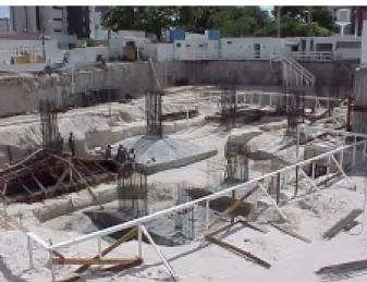
Another set of innovations is related to the form of the building and how it is located in the terrain. Fortaleza is situated in the northeast of Brazil in a sea coast facing north. Average temperature is quite high, in the range of 30 Celsius during the day. Winds come predominantly from the sea helping to provide better thermal comfort. This makes it absolutely desirable to have all apartments with their bedrooms and living rooms facing northeast. Kitchens, laundries and external corridors are situated on the opposite side (southwest). This results in thin buildings, with some 10 meters wide and in this case 40 meters long, to accommodate five apartments per story. Moreover, in order to lay down this rectangular shape block into the terrain, a larger piece of land should be employed, in order to rotate the tower block to the convenient northeast solar orientation. The end result is that the tower block occupies a small proportion of the plot of land, leaving a lot of room for the temporary site layout. On the other hand, from the main office it is possible to control the whole site as it can be seen in figure 1, depicting foundation work.
Figure 1: View of foundation work from the main site office
The rectangular shape of building allows a linear construction. Not only it is possible to see the progress of work in a Line of Balance fashion, first with the activities going through the various stories bottom up and then top down, but it is also straightforward to plan linearly the work along the length of each story.
PRECEDENCE RELATED VISIBILITY
A number of sequencing decisions make the work even more visible. Floor screeding is laid down while the bricklaying internal partitions are not yet in place. External bricklaying is placed as soon as possible, in order to avoid temporary safety measures to protect workers from falling through the edges of the reinforced concrete structure. Mortar ceiling plastering is placed also with no internal partitions in position.
USE OF EQUIPMENT TO MAKE VISIBLE HIDDEN SPOTS
Invisible spots are made visible through the use of video cameras. One example is the cargo lift, which is operated by an operative sitting near the hoisting mechanism situated at ground floor level. This site staff is able to control all the loading/unloading operations from the cargo lift in each story by observing a video camera. This contributes to the safe operation of the cargo lift equipment. Key personnel on site use walkie-talkie radios to improve communications and find out each others´ whereabouts.
Every site location is clearly signaled by identification tags. Work location and gang number identification are central to the workings of the short term site programming being used on site. This hand help based system will be described by the end of the paper.
TRANSPARENCY DUE TO ANTICIPATORY WORK
A number of anticipatory activities introduce a special kind of visibility on site. They work as a kind of reminder of what is expected to come as part of the activities when they finally are performed. The most striking example is the system of flood control that was already described in the layout section of this paper. The watertight barriers are prominently visible to all that have any contact with the building, as workers, clients or just passers by. It reminds all those involved that rain will come and special care should be taken with an extra activity normally not taken into account, namely permanent site drainage.
Temporary water and electricity provision are all set in advance of needs, using as much as possible pipes and runways that will be used in the final building. Every room in the 23 stories has an illumination socket, which might be provided with a lamp and switched on when work is in progress. This literally increases visibility and also reminds workers that dark spots are not an excuse for poor workmanship. It also counteracts the natural tendencies of workers to hide away in the intricate dark labyrinth of internal partition walls. Further than that, it allows immediate recognition of locations that are being worked on, if lights are lit.
Sand is passed through sieves mounted on the top of a mechanical vibrator. This preparatory work is made at the center of the mortar and concrete mixing installation, making clear to all those concerned the quality required in mortar rendering. The mechanical sieve works as a showpiece at a quite visible setting on the ground floor layout.
Concrete totems 40x40x100cm high are disposed at the ground floor area around the main tower, allowing precise alignment of each storey with orthogonal reference axis. A laser level is constantly used on site, creating an imaginary perfect virtual horizontal plane at some 1-meter high. Workers become aware that real horizontal planes, both at floor and ceiling level might be easily checked against this reference. Leveling only becomes reality when specific key points are checked, but it can be hypothesized that one of the laser level contributions is the creation in everybody’s mind of a virtual horizontal reference plan.
TRANSPARENCY DUE TO WORKING DRAWINGS
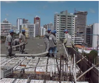
Specific working drawings are issued for concrete slab production, floor screeding, bricklaying and ceramic tile façade covering. The first set of working drawings covers concrete slab production. This structural component is executed with a 25 cm thick slab composed of the following elements: there is a thin 4cm concrete covering layer on the top of a grid of beams 40x40cm and 21 cm deep. The space in between the beam’s grid is filled with hollow ceramic blocks complemented by a layer of polystyrene foam 7 cm deep. This solution was arrived at in order to get a flat mortar ceiling. Previously voids were left open, making it necessary to have a gypsum plasterboard ceiling. Its quality, durability and costs were unacceptable. Moreover they represent one more operation performed by subcontracted gangs, which was against the building company policy of employing as much as possible its own labor. Figure 2 illustrates the concrete slab composition and its pouring operation.
The exact position of the grid of beams and the filling blocks should be decided in advance, in order to make it easy to accommodate descending electrical, water and sanitation pipes through the 4 cm final concrete layer. It will be troublesome if the descending pipes require perforating the concrete grid beams 21cm deep. Moreover, decisions should be taken on where different sizes of grids should be employed to compensate non-modular dimensions of the concrete slab. All non-standard grids are clearly marked on working drawings.
Figure 2: Concrete pouring on the top of the ceramic and polystyrene blocks
It is interesting to note that ceramic blocks are glued together with the polystyrene sheets in advance. This prefabrication is done in an open space at ground level, making it easy to control the rhythm of production.
Floor screeding leaves marks on its mortar surface indicating the exact position of each wall and door opening to be erected on it. Very early in the building process it is possible to have a grasp of the final bricklaying layout of each apartment. Bricklaying axes are taken from specific brickwork drawings.
Bricklaying is performed in accordance with the needs of each specific project, detailing the position of each ceramic block, openings, air conditioning concrete frames and lintels. Due to the fact that both the final dimensions of the concrete structure differs slightly from its design and ceramic blocks do not have exactly their nominal dimensions, it proved to be very hard to assure the exact positioning of each element in the wall. A system was designed to overcome this problem, allowing bricklayers to make a prototype of each wall, using wooden blocks in the scale 1:6.66. Those wooden blocks have a thin layer of a magnetic film, making it possible to fix them on the top of an iron plate. Instead of trying to fix each block on its exact position, bricklayers try to simulate the construction of the wall taking into account only its more important axes, like vertical position of windows and doors, vertical position of descending electrical and plumbing pipes, and horizontal position of lintels. Only after this prototype wall has been approved by the general foreman, bricklayers are allowed to proceed with their job. Thus, virtual walls are actually seen twice before they are built, one as working drawings are examined and another time when simulated walls are constructed.
While bricklaying, care should be taken to allow electrical pipes to run inside the walls through vertical and horizontal hollows in the ceramic blocks. Their positioning is a matter of careful decision, since they descend from the concrete slab in a spot that do not necessarily match the vertical hollow of the ceramic block that is supposed to take it. At yet there are no working drawings coordinating electrical pipes left to descend from the concrete slabs and the precise hollow they should run on the bricklaying wall. As bricklayers are building their simulation model walls they should compare them with the actual positioning of electrical pipes let down from the concrete slab.
Ceramic blocks are prepared in advance to incorporate the final width of wall mortar rendering. Blocks incorporating the final rendering width become wider than standard blocks. Four special ceramic blocks already rendered are placed at the corners of each wall, making it possible afterwards to get a rendered vertical plane by leveling out mortar against these larger blocks with an aluminum ruler. Very early in the bricklaying process it is possible to figure it out not only how the final wall will look, but also the implications of its final width to succeeding finishing details, like the exact positioning of wooden doorframes. Again the special rendered blocks are prepared in front of everyone’s eyes, signaling that the wall is wider than just their ceramic blocks.
The notion that every centimeter is of tantamount importance is vital to this apartment building construction, due to its small size: corridors, door openings, and bathroom sanitary appliances are all set to their minimum space requirement: if wall rendering or tiling is thicker than specified, these features will not work properly.
Façades are all in ceramic tiles 10x10 cm. It is unfortunate that the size and positioning of windows do not follow a module of 10cm. The same happens with the height of each story. Thus before ceramic rendering it is necessary to analyze how it is possible to avoid cuttings to accommodate non-modular distances between window openings and story height. Moreover many different colors are used in vertical and horizontal strips, requiring what is called pagination in Brazilian construction practice. Virtual pagination is performed initially through working drawings. After that, real pagination is performed by plumbing wires all around the façade and gluing key ceramic tiles on their final position. Potentially all non-modular vertical and horizontal distances can be covered with no tile cuts just by increasing/decreasing in invisible amounts the nominal joints of 1 cm between ceramic units. The end result is that this 1:1 scale façade design using wires and key tiles positioning makes it possible to understand what the building will look like much earlier than the actual façade covering operation is performed.
TECHNOLOGICAL DEVELOPMENTS AND THE FLOW OF OPERATIONS
Two technological advances in bricklaying and floor screeding operations also increase transparency, highlighting the flow of activities to conduct them from start to finish. Bricklaying is performed taking care of all its flow operations, introducing small technological developments in every step under way. Bricks are unloaded to special docks scattered along the transparent site fence. Docks are at the same height as the lorry platform. Bricks are arranged into pallets by hand and then carried to the cargo lift by special wheelbarrows. The pathway from the storage area to the cargo lift is previously rendered with a mortar screed, in order to assure smooth running, This also helps to indicate the shortest possible transportation distance and it signals that this pathway cannot be interrupted by temporary storage of other materials or any other sort of flow restriction.
Sand and cement are mixed in quantities specified on a colorful board fixed at the mixing area. Specially designed colorful gauged wheelbarrows will take the exact quantities of sand to the mixer, that together with 50 kg cement bag will produce a mortar batch.
The special wheelbarrows carrying the bricks pallets were designed to fit the cargo lift platform, with no spare space and easy in and out maneuvering. Brick pallets are deposited along the walls to be erected, in places previously determined by the general
foreman. Mortar is stored in movable containers, which will hold all bricklayer equipment, water and a container to collect brick debris. Internal scaffolds were designed for safety, stability, easy of assembling /disassembling and cleaning.
Thus, the bricklaying operation works as a testimony of how flow should be improved on site before conversion is addressed. It represents what is possible given the current building industry supply chain maturity. For example, it is yet not possible to get bricks already in pallets from the ceramic producer, nor is the use of tower hoists widely spread in Fortaleza.
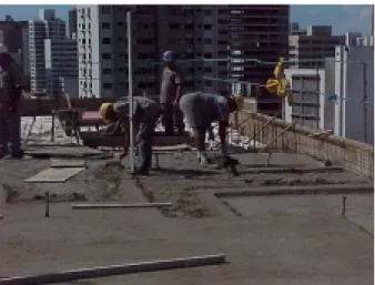
Floor screeding gives an example of a different lean approach to flow and conversion. It was decided to lay floor screeding just after the concrete slab is poured into place. The same cargo lift will take alternatively concrete for the slab and mortar for floor screeding. The same laser level will determined both final concrete slab and floor screeding height. Different gangs are responsible for each operation, but they work visually in close contact, adapting reciprocally their rhythm of work. Both operations are conducted on a slow pace of work, aiming at quality of the final product. Normally concrete pouring is taken as an operation where both site management and the operatives should demonstrate their vigor and hard work, at the expense of adherence to the geometric reinforced structure specifications and quality of concrete vibration. Figure 3 shows the floor screeding operation being performed just after concrete pouring (white polystyrene infill blocks appearing at the back are still waiting for their concrete coverage). Setbacks are left on the floor screeding surface marking the position where brick walls will be put into place.
Operational advantages are connected to the fact that general foreman will control both operations simultaneous. Worker’s water supply and sanitary facilities are placed in the vicinity and will serve both gangs of workers. Technically concrete curing will be improved by the wet, protective layer of floor screeding on its top.
Figure 3: Floor screeding and setbacks for brick walls positioning
The floor screeding approach is an example of cellular like arrangement of workers, decrease of buffers between operations, flow synchronization, steady but just appropriate rhythm of work, job enlargement (as an operation from a different activity is incorporated, namely bricklaying first course setting), and decreasing site management overhead costs. Nothing was actually changed in the conversion process of the two operations. Just assuring the synchronization of both conversion activities, productivity
gains were expected, through intra-motivation of crews and better use of auxiliary resources, like laser leveling and managerial surveillance. A separate paper for this conference describes in detail how this was accomplished, yielding a 38% cost reduction just for this operation and a 12% cost reduction for the combined concrete slab and floor screeding operation.
Labour Measurement and Site Productivity
The computing system is based on an accounting software package that is capable of providing cost control information at the level of individual operations on site. Individual operations are previously cost estimated and then exported to a CPM strategic plan for the whole building. The network of activities is displayed at the site office. Both site engineer and the general foreman get in touch at the end of each working day to agree upon the activities to be carried out the next day. Daily production orders are issued and distributed among the workers. A handheld computer has been introduced allowing checking and measuring of work in progress while going around the site. At each observational round the handheld operator will check each activities progress, changing their status from on going to measured, finished, technically approved or recommended for rework. Every time physical work is measured and introduced to the hand held computer information will be fed back stating if the activity is on schedule or otherwise. Reasons for delayed status or rework are assessed and informed to the computer. It is believed that this procedure expands the last planner concept, by fine tuning and checking of activities that are supposedly being performed without disturbance as they were taken from a protected backlog list of jobs. Experience has indicated that the vagaries of site productivity are such that it is permanently necessary to check if activities are following the schedule, yielding high PPC marks. Moreover, job quality as assessed by the foreman, should be concomitantly evaluated. The system was developed aiming at reducing administrative costs. Most of the administrative activities that it requires were already performed in order to prepare site payroll.
It became obvious that the next step to improve visibility on this site was to display production and productivity information back to the operatives, using the output from the computer system described earlier. First, there are a number of motivational issues that might be associated with this attitude. Second it works as a justification in the operatives eyes for the administrative staff monitoring, checking and analysis of their performance. Notwithstanding that, the main reason for production assessment is to answer everybody questions related to how worthwhile are all the innovations described throughout this paper.
It should be said that from the start of the nineties a substantial number of building companies all over Brazil started quality and productivity improvements on their sites. None of them can justify their adoption of innovations on actual cost reductions or any other performance measurement, due to the simple reason that rarely production measurement is performed. It is possible to find innovative building firms operating without a detailed cost estimate of their jobs. Thus, the adoption of technological and managerial innovations was an act of faith, marketing strategy or just good common sense. For the first time it will be possible to compare performance before and after innovations are introduced using this handheld computing system. Previous cost control systems in use by this building company provide information at a very coarse level of
detail. Up to 1994 the high level of inflation prevailing in the Brazilian country prevented the use of any meaningful system of managerial cost accounting.
The unit of work for measuring purposes comprises each pavement of the 23 story high tower block. Production is assessed in terms of the number of days a gang takes to finish each pavement job. Thus information is displayed on the number of days to finish the reinforced concrete structure, mortar ceiling rendering, floor screeding, external bricklaying, internal bricklaying, and all other activities that are enrolled in the estimates and in the CPM program.
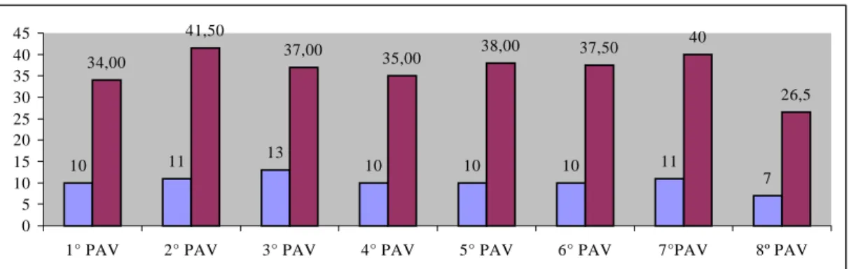
Moreover, further information is added containing flow implications. For example flow activities for floor ceiling first coat and final coat rendering are associated with the number of mortar mix batches that are delivered from the mixing installation situated at ground floor level. Producing mortar and transporting them horizontally to the cargo lift, then vertically and finally horizontally to the discharging area is a demanding task for these operations. It is not really a problem of big volumes to be handled, but the fact that the cargo lift is busy with concrete and floor screeding construction some stories above. Reducing the number of batches helps to minimize conflicts over the cargo lift utilization. Figures 4 and 5 show production graphs both for first coat and final coat ceiling rendering. Operatives might examine these graphs and figure out that it is possible to perform the first operation in some 6 days, using 11 batches, while the second requires 10 days and 36 batches, according to the averages shown.
6 6 6 6 6 6 6 7 7 4 11 12 11,5 11 11,5 8,5 8,5 11,5 12,5 8,5 0 2 4 6 8 10 12 14
1º PAV 2º PAV 3º PAV 4º PAV 5º PAV 6º PAV 7º PAV 8º PAV 9º PAV 10º PAV
Figure 4: Production graphs for first ceiling rendering coat – duration and number of mortar batches in each story.
10 11 13 10 10 10 11 7 34,00 41,50 37,00 35,00 38,00 37,50 40 26,5 0 5 10 15 20 25 30 35 40 45
1° PAV 2° PAV 3° PAV 4° PAV 5° PAV 6° PAV 7°PAV 8º PAV
Figure 5: Production graphs for final ceiling rendering coat – duration and number of mortar batches in each story.
CONCLUSIONS
The majority of innovations that have been introduced on this building site increase transparency and visibility of operations. Operatives might better understand how the flow of resources is organized and what sort of activities are being performed today to improve processes in the near future. An additional effort that would further increase transparency is the use of handheld computers to collect productive data showing cost savings of the previous innovations. Evidence is already available in connection with floor screeding executed just after concrete slab pouring, yielding a 12% total cost saving for these operations taken as a whole. Further evidence in connection with other activities performed on this site will reinforce the adoption of transparency innovations not only as an act of faith and good common sense, but in economical sense.
REFERENCES
Scardoelli, L., Silva, M.F.S., Formoso, C. T., Heineck, L. F. M. (1994). “Melhorias de qualidade e produtividade: iniciativas das empresas de construção”. Série SEBRAE Construção Civil, SEBRAE, R.G do Sul, Brasil
Santos, Aguinaldo. (1999). “Application of flow principles in the production management of construction sites”. Doctoral thesis submitted to the University of Salford, Salford, U.K.