A
University
of
Sussex
PhD
thesis
Available
online
via
Sussex
Research
Online:
http://sro.sussex.ac.uk/
This
thesis
is
protected
by
copyright
which
belongs
to
the
author.
This
thesis
cannot
be
reproduced
or
quoted
extensively
from
without
first
obtaining
permission
in
writing
from
the
Author
The
content
must
not
be
changed
in
any
way
or
sold
commercially
in
any
format
or
medium
without
the
formal
permission
of
the
Author
When
referring
to
this
work,
full
bibliographic
details
including
the
author,
title,
awarding
institution
and
date
of
the
thesis
must
be
given
Spectrally Efficient Non-Orthogonal
Multiple Access (NOMA) Techniques
for Future Generation Mobile
Systems
By
Ibrahim Bukar
Submitted for the degree of Doctor of Philosophy
School of Engineering and Informatics
University of Sussex
2016
Declaration
I hereby declare that this thesis has not been and will not be submitted in whole or in part to another University for the award of any other degree.
Signature:
Ibrahim Bukar
UNIVERSITY OF SUSSEX
Thesis submitted in fulfilment of the requirements for the degree of Doctor of Philosophy
Spectrally Efficient Non-Orthogonal Multiple Access (NOMA) Techniqes for Future Generation Mobile Systems
By: Ibrahim Bukar Summary
With the expectation of over a 1000-fold increase in the number of connected devices by 2020, efficient utilization of the limited bandwidth has become ever more important in the design of mobile wireless systems. Furthermore, the ever-increasing demand for higher data rates has made it necessary for a new waveform design that satisfies not only throughput demands, but network capacity as well. One such technique recently proposed is the non-orthogonal multiple access (NOMA) which utilizes the distance-dependent power domain multiplexing, based on the principles of signal superposition. In this thesis, new spectrally efficient non-orthogonal signal techniques are pro-posed. The goal of the schemes is to allow simultaneous utilization of the same time-frequency network resources. This is achieved by designing component signals in both power and phase domain such that users are precoded or preformed to form a single and uniquely decodable composite signal. The design criteria are based on maximizing either the sum rate or spectral efficiency, minimizing multi-user interference and de-tection ambiguity, and maximizing the minimum Euclidean distance between the com-posite constellation points. The design principles are applied in uplink, downlink and coordinated multipoint (CoMP) scenarios. We assume ideal channel state with perfect estimation, low mobility and synchronization scenarios so as to prove the concept and serve as a bound for any future work in non-ideal conditions. Extensive simulations and numerical analysis are carried to show the superiority and compatibility of the schemes. First, a new NOMA signal design called uplink NOMA with constellation precoding is proposed. The precoding weights are generated at the eNB based on the number of users to be superposed. The eNB signals the precoding weights to be employed by the users to adjust their transmission. The adjustments utilize the channel state information estimated from common periodic pilots broadcasted by the eNB. The weights ensure the composite received signal at the eNB belongs to the pre-known constellation. Further-more, the users precode to the eNB antenna that requires the least total transmit power
from all the users. At the eNB, joint maximum likelihood (JML) detection is employed to recover the component signals. As the composite constellation is as that of a single user transmitting that same constellation, multiple access interference can be viewed as absent, which allows multiple users to transmit at their full rates. Furthermore, the power gain achieved by the sum of the component signals maximizes the sum rate.
Secondly, the constellation design principle is employed in the downlink scenario. In the scheme, called downlink NOMA with constellation preforming, the eNB preforms the users signal with power and phase weights prior to transmission. The preforming ensures multi-user interference is eliminated and the spectral efficiency maximized. The preformed composite constellation is broadcasted by the eNB which is received by all users. Subsequently, the users perform JML detection with the designed constellation to extract their individual component signals. Furthermore, improved signal reliability is achieved in transmit and receive diversity scenarios in the schemes called distributed transmit and receive diversity combining, respectively.
Thirdly, the constellation preforming on the downlink is extended to MIMO spatial multiplexing scenarios. The first MIMO scheme, called downlink NOMA with constel-lation preforming, each eNB antenna transmits a preformed composite signal composed of a set of multiple users’ streams. This achieves spatial multiplexing with diversity with less transmit antennas, reducing costs associated with multiple RF chains, while still maximizing the sum rate. In the second MIMO scheme, a highly spectrally effi-cient MIMO preforming scheme is proposed. The scheme, called group layer MIMO with constellation preforming, the eNB preforms to a specific group of users on each transmit antenna. In all the schemes, the users perform JML detection to recover their signals.
Finally, the adaptability of the constellation design is shown in CoMP. The scheme, called CoMP with joint constellation processing, the additional degrees of freedom, in form of interfering eNBs, are utilized to enable spatial multiplexing to a user with a single receive antenna. This is achieved by precoding each stream from the coordinating eNB with weights signalled by a central eNB. Consequently, the inter-cell interference is eliminated and the sum-rate maximized. To reduce the total power spent on precod-ing, an active cell selection scheme is proposed where the precoding is employed on the highest interferers to the user. Furthermore, a power control scheme is applied the design principle, where the objective is to reduce cross-layer interference by adapting the transmission power to the mean channel gain.
Acknowledgements
First, I would like to express my sincere appreciation and everlasting gratitude to my beloved parents Mustapha and Rakiya Bukar, my beloved wife Maryam, and the entirety of our family. Their love, support and huge sacrifices will never be forgotten. I dedicate this thesis for you and hope it will make you proud.
My sincerest gratitude to my supervisor Dr Falah Ali. I thank him for his unlim-ited patience, time, honest criticism, and encouragement throughout the duration of my studies. His thorough understanding of wireless communications, creativity, and work ethics has been a source of inspiration to me and has helped me throughout my studies. Finally, I would also like to think my colleagues at the communication research lab: Murtala Aminu, Tom Hayes, Fei, Andreas, and Victor. Their help, support, and friend-ship have made the past four years an enjoyable experience.
List of Publications
• I. Bukar and F. Ali, "Subcarrier Multiplexing in LTE-COMP OFDMA", in2015 IEEE 81st Vehicular Technology Conference (VTC Spring), 2015, pp. 1-5.
• I. Bukar and F. Ali, "Highly Spectrally Efficient NOMA Constellation Designs",To be Submitted to: IEEE Communication Letters.
• I. Bukar and F. Ali, "Downlink NOMA with Constellation Preforming",To be Sub-mitted to: IET Journal on Communication.
• I. Bukar and F. Ali, "Spectrally Efficient MIMO NOMA with Constellation Preform-ing",To be Submitted to: IET Journal on Communication.
List of Abbreviations
Abbreviation Definition
3G 3rd Generation
3GPP 3rd Generation Partnership Project
4G 4th Generation
5G 5th Generation
5GNOW 5th Generation Non-Orthogonal Waveforms
ACS Active Cell Selection
AWGN Additive White Gaussian Noise
BD Block Diagonalization
BER Bit Error Rate
BS Base Station
CCI Co-Channel Interference
CDMA Coding Division Multiple Access
CeNB Coordinating eNB
CI Channel Inversion
CN Core Network
CoMP Coordinated Multipoint
CP Cyclic Prefix
CPP Common Periodic Pilot
CRS Cell-Specific Reference Signals
CS/CB Coordinated Scheduling/Beamforming
CSI Channel State Information
CSIR Channel State Information at the Receiver
CSIT&R Channel State Information at Transmitter and Receiver
dmin Minimum Euclidean Distance
DL-SCH Downlink Shared Channels
DPC Dirty Paper Coding
eNB EUTRAN-NodeB
EP Equal Power
EPC Enhanced packet Core
FDD Frequency Domain Duplex
FDMA Frequency Division Multiple Access
FFT Fast Fourier Transform
Gbps Gigabits per Second
GMAC Gaussian Multiple Access Channel
H-ARQ Hybrid Automatic Requests
i.i.d independently identically distributed
ICI Inter-Channel-Interference
IFFT Inverse Fast Fourier Transform
IP Internet Protocol
ISI Inter-Symbol Interference
JCP Joint Constellation Processing
JML Joint Maximum Likelihood
JP Joint Processing
LDS Low-Density Spreading
LTE Long Term Evolution
LTE/A Long Term Evolution/Advanced
LUT Look Up Table
M2M Machine-to-Machine
MAC Multiple Access Channel
M-AC Medium-Access Control
MAI Multiple Access Interference
MAS Multiple Access Schemes
Mbps Megabits per Second
MCA Mean Channel Adaptation
MCG Mean Channel Gain
METIS The Mobile and wireless communication Enablers for the
Twenty-twenty Information Society
MISO Multi-Input Single-Output
MMSE Minimum Square Error
MPA Message-Passing Algorithm
MRC Maximum Ratio Combing
MUD Multi-User Detection
MUI Multiple User Interference
MU-MIMO Multiuser MIMO
MUSA Multi-User Shared Access
NCPf NOMA with Constellation Preforming
DTAD Distributed Transmit Antenna Diversity
RD Receive Diversity
NOMA Non-Orthogonal Multiple Access
OFDM Orthogonal Frequency Division Multiplexing
OFDMA Orthogonal Frequency Division Multiple Access
OMA Orthogonal Multiple Access
PAPR Peak-to-Average Power Ratio
PBCH Physical Broadcast Channel
PDCCH Physical Downlink Control Channel
PDCP Packet Data Convergence Protocol
PDF Probability Density Function
PDMA Pattern Division Multiple Access
PD Power Domain
PDSCH Physical Downlink Shared Channel
PHY Physical Layer
PMCH Physical Multicast Channel
PMI Precoder-Matrix Indication
PRACH Physical Random-Access Channel
PUCCH Physical Uplink Control Channel
PUSCH Physical Uplink Shared Channel
QoS Quality of Service
RAN Radio-Access Network
RB Resource Blocks
RE Resource Element
RI Rank Indication
RLC Radio-Link Control
RRM Radio Resource Management
SC-FDMA Single Carrier Frequency Division Multiple Access
SCMA Sparse-Code Multiple Access
SER Symbol Error Rates
SIC Successive Interference Cancellation
SIMO Single-Input Multi-Output
SINR Signal-to-Interference-Plus-Noise Ratios
SM Spatial Multiplexing
SMD Spatial Multiplexing and Diversity
SNR Signal-to-Noise Ratio
SPC Superposition Coding
SRS Sounding Reference Signals
STBC Space-Time Block Coding
SU-MIMO Sinlge User MIMO
SVD Singular Value Decomposition
TCI Truncated Channel Inversion
TDD Time Domain Duplex
TDMA Time Division Multiple Access
THP Tomlinson-Harashima Precoding
TTI Transmission Time Interval
UHD Ultra High Definition
NCPr NOMA with Constellation Precoding
UL-SCH Uplink Shared Channels
UP Unequal Power
WiMAX Worldwide Interoperability for Microwave Access
List of Notations
|h| Magnitude of complex valueh khk Vector Euclidean norm
(·)∗ Conjugate transposition
(·)T Transposition
Cm×n Complexm×umatrix
E Expectation value
ℵ(m, n) Meanmwith variancen
H† Moore-Penrose inverse of matrixH
H(x) Entropy ofx
Im m×nIdentity matrix
min(m, n) Minimum elements
tr(·) Matrix trace
Contents
List of Tables xx
List of Figures xxviii
1 Introduction 1
1.1 Motivation . . . 1
1.2 Research Aims and Objectives . . . 3
1.3 Contributions of the Thesis . . . 4
1.4 Outline of the Thesis . . . 6
2 Technical Background 9 2.1 LTE and LTE-Advanced . . . 9
2.1.1 Introduction . . . 9 2.1.2 LTE Architecture . . . 10 2.1.3 EUTRAN-NodeB (eNB) . . . 11 2.1.4 Physical transmission . . . 12 2.1.4.1 Frame Structure . . . 13 2.1.4.2 Synchronization . . . 15
2.1.4.4 Downlink Physical-Layer Transmission . . . 16
2.1.5 Coordinated Multi-Point (CoMP) . . . 17
2.2 Multiple Access Techniques . . . 19
2.2.1 Orthogonal Multiple Access (OMA) Schemes . . . 19
2.2.1.1 Time Division Multiple Access (TDMA) . . . 19
2.2.1.2 Frequency Division Multiple Access (FDMA) . . . 20
2.2.1.3 Orthogonal Frequency Division Multiplexing (OFDMA) 21 2.2.1.4 Single Carrier-Frequency Division Multiple Access (SC-FDMA) . . . 23
2.2.2 Non-Orthogonal Multiple Access (NOMA) Schemes . . . 24
2.2.2.1 Power Domain NOMA (PD-NOMA) . . . 24
2.2.2.2 Coding Division Multiple Access (CDMA) . . . 26
2.2.2.3 Low-Density Spreading (LDS) . . . 28
2.2.2.4 Sparse-Code Multiple Access (SCMA) . . . 28
2.2.2.5 Multi-user Shared Access (MUSA) . . . 29
2.2.2.6 Pattern-Division Multiple Access (PDMA) . . . 29
2.3 Multiple Antenna Techniques . . . 30
2.3.1 Multiple Input Multiple Output (MIMO) Communications . . . . 31
2.3.1.1 Single-User MIMO (SU-MIMO) . . . 31
2.3.1.2 Multi-user MIMO (MU-MIMO) . . . 33
2.3.2 Precoding . . . 35
2.3.2.1 Linear Precoding . . . 35
2.3.2.2 Non-linear Precoding . . . 35
2.3.2.4 Block Diagonalization (BD) . . . 38
2.3.3 Signal Detection . . . 40
2.3.3.1 Maximum Likelihood (ML) Detection . . . 40
2.3.3.2 Zero Forcing Detection . . . 41
2.3.3.3 Minimum Mean Squared Error (MMSE) Detection . . . 41
2.3.3.4 SIC Detection . . . 42
2.4 Future 5G . . . 42
2.4.1 Requirements . . . 43
2.4.2 Key Technologies and Challenges . . . 44
3 Uplink NOMA with Constellation Precoding (UL-NCPr) 47 3.1 Introduction . . . 47
3.2 Motivation and Related Work . . . 49
3.3 Principles of Constellation Precoding . . . 51
3.4 Operational Example of UL-NCPr . . . 52
3.5 System Model . . . 54
3.5.1 Channel Model . . . 55
3.5.2 Signal Model . . . 55
3.5.3 Constellation Design . . . 58
3.5.3.1 Design Objectives and Considerations . . . 58
3.5.3.2 Constellation Search Algorithm and Procedures . . . . 59
3.5.3.3 Equal Power, Unequal Power and Rotated Component Constellations . . . 63
3.5.3.4 Equal Rate Component Constellations . . . 65
3.5.4 Antenna Selection . . . 70
3.5.5 Joint Maximum Likelihood Detection . . . 70
3.6 Signalling and Synchronization . . . 72
3.6.1 Common Periodic Pilot (CPP) . . . 72
3.6.2 Synchronization . . . 73
3.7 Performance Analysis . . . 74
3.7.1 Capacity . . . 74
3.7.2 Bit Error Rate . . . 76
3.8 Simulation Modelling and Results . . . 79
3.8.1 Simulation Modelling . . . 79
3.8.2 Results . . . 80
3.9 Conclusion . . . 90
4 Downlink NOMA with Constellation Preforming 91 4.1 Introduction . . . 91
4.2 NOMA with Constellation Preforming (NCPf) . . . 92
4.2.1 Principles of NCPf . . . 92
4.2.2 System Model . . . 93
4.2.2.1 Signal Model . . . 93
4.2.2.2 Constellation Preforming and Algorithm . . . 95
4.2.2.3 Joint Maximum Likelihood Detection and Recovery . . 100
4.3 Performance Analysis . . . 101
4.4 Simulation Modelling and Results . . . 102
4.4.1 Simulation Model . . . 102
4.5 Conclusion . . . 108
5 Downlink Multi-Antenna NOMA with Constellation Preforming 110 5.1 Introduction . . . 110
5.2 NOMA Constellation Preforming with Spatial Diversity . . . 112
5.2.1 NOMA Constellation Preforming with Receive Diversity (NCPf-RD) Combining . . . 112
5.2.2 NOMA Constellation Preforming with Distributed Transmit An-tenna Diversity (NCPf-DTAD) . . . 113
5.3 MIMO NOMA Constellation Preforming with Spatial Multiplexing and Diversity (NCPf-SMD) . . . 115
5.3.1 Introduction . . . 115
5.3.2 System Model . . . 116
5.3.2.1 Maximum Likelihood Joint Detection and recovery . . 118
5.3.2.2 Zero Forcing ML Detection . . . 119
5.4 MIMO with Group Layered NOMA Constellation Preforming (GL-NCPf) 119 5.4.1 System Model . . . 119
5.4.2 Maximum Likelihood Joint Detection with Interference Suppres-sion . . . 121
5.5 Performance Analysis . . . 122
5.5.1 NOMA Constellation Preforming with Spatial Diversity . . . 122
5.5.1.1 NCPf-RD . . . 122
5.5.1.2 NCPf-DTAD . . . 124
5.5.2 NCPf-SMD . . . 124
5.6 Simulation Modelling and Results . . . 127 5.6.1 Simulation Models . . . 127 5.6.1.1 NCPf-RD and NCPf-DTAD . . . 127 5.6.1.2 NCPf-SMD . . . 129 5.6.1.3 GL-NCPf . . . 130 5.6.2 Results . . . 131 5.6.2.1 NCPf-RD and NCPf-DTAD . . . 131 5.6.2.2 NCPf-SMD and GL-NCPf . . . 133 5.7 Conclusion . . . 136
6 Coordinated Multipoint (CoMP) NOMA with Joint Constellation Processing (CoMP-JCP) 137 6.1 Introduction . . . 137
6.2 Motivation and Related Work . . . 139
6.3 Principles of Joint Constellation Processing . . . 141
6.4 Joint Constellation Processing (CoMP-JCP) . . . 142
6.4.1 System Model . . . 142
6.4.2 Maximum Likelihood Detection . . . 144
6.4.3 Joint Constellation Processing Procedures . . . 145
6.5 Joint Constellation Processing with Active Cell Selection (CoMP-JCP-ACS) 146 6.5.1 System Model . . . 147
6.5.2 Active Cell Selection and Transmission Procedures . . . 148
6.6 CoMP Joint Constellation Processing with Mean Channel Adaptation (CoMP-JCP-MCA) . . . 150
6.7 Simulation Modelling and Results . . . 153
6.7.1 Simulation Modelling . . . 153
6.7.1.1 CoMP-JCP and CoMP-JCP-ACS . . . 153
6.7.1.2 CoMP-JCP-MCA . . . 154
6.7.2 Results . . . 155
6.8 Conclusion . . . 163
7 Conclusion and Future Work 164 7.1 Conclusions . . . 164
7.2 Future Work . . . 168
List of Tables
2.1 LTE resource parameters defined in LTE standard . . . 14 3.1 Algorithm variable definitions including their notation, size and search range. . 60 3.2 UL-NCPr constellation design example for a 2 to 4 user equal power (EP)
alloc-ation case. The table shows the component and composite constellalloc-ations. The phase precoding anddminof the composite constellations are given for each case.
The amplitude is assumed equal to one for all users . . . 63 3.3 UL-NCPr constellation design example for unequal power (UP) 2-user and 3-user
cases each employing BPSK and/or 4-QAM. The size of the composite constella-tion, power allocaconstella-tion, phase rotation and the dmin of the composite
constella-tions are also provided. . . 64 3.4 UL-NCPr example of two to four users all employing BPSK. Their individual
power allocations, relative phase shifts and the size of their composite constel-lation are given. The PD-NOMA with power allocation only is also given for comparisons. The composite constellationdminfor both schemes are presented 67
3.5 UL-NCPr example of two and three users all employing 4-QAM. Their individual power allocations, relative phase shifts and the size of their composite constella-tion are given. The composite constellaconstella-tiondminfor both schemes are presented
3.6 UL-NCPr example of two users all employing variable component modulations. Their individual power allocations, relative phase shifts and the size of their com-posite constellation are given. The comcom-posite constellationdminfor both schemes
are presented . . . 68 4.1 Example of two and three users all employing BPSK. Their individual power
al-locations as a fraction ofP, relative phase shifts and the size of their composite constellation are given. The composite constellationdminfor both schemes are
presented . . . 97 4.2 Example of two and three users all employing 4-QAM. Their individual power
allocations as a fraction ofP, relative phase shifts and the size of their composite constellation are given. The composite constellationdminfor both schemes are
presented . . . 97 4.3 UL-NCPr example of two users all employing variable component modulations.
Their individual power allocations, relative phase shifts and the size of their com-posite constellation are given. The comcom-posite constellationdminfor both schemes
List of Figures
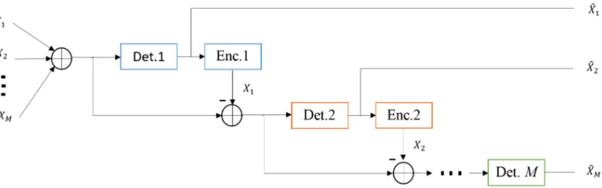
2.1 LTE high level network architecture . . . 11 2.2 LTE time domain frame architecture . . . 14 2.3 LTE time and frequency resource block . . . 15 2.4 Joint Processing in Coordinated Multipoint . . . 18 2.5 Coordinated Scheduling/Beamforming in Coordinated Multipoint . . . 18 2.6 Orthogonal TDMA and FDMA resource allocation . . . 20 2.7 OFDMA resource allocation and modulation . . . 22 2.8 SC-FDMA resource allocation and modulation . . . 23 2.9 Power domain NOMA resource allocation . . . 26 2.10 Code division multiple access resource allocation . . . 27 2.11 Multi-antenna techniques including SIMO, MISO and MIMO . . . 31 2.12 Single user MIMO system . . . 32 2.13 Multiuser MIMO system . . . 34 2.14 Spatial Multiplexing by singular value decomposition precoding . . . 38 2.15 Successive interference cancellation (SIC) with power ordering X1>X2> . . . >XM 42
3.1 Uplink NOMA with Constellation Precoding system model with M users trans-mitting to an eNB equipped with L antennas. . . 54
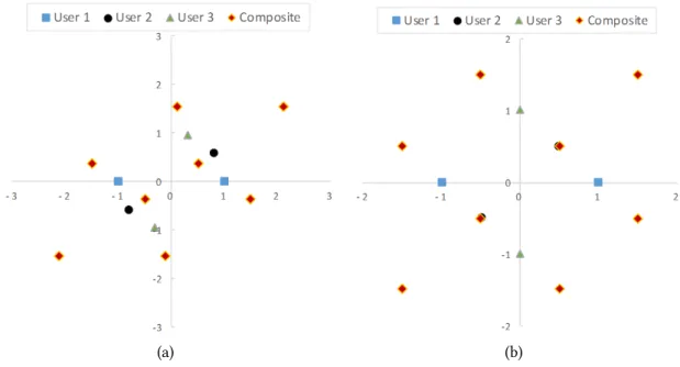
3.2 Superimposed component and composite constellation of three users each em-ploying BPSK. Base component constellation reference of(0◦,180◦)is assumed.
(a) Superimposed component constellations of EP users with phase allocations of β1= 0◦, β2= 36◦, β3 = 72◦. (b) Superimposed component constellations of
UP users with UP and phase allocations of D1 = 1.0,D2 = 0.7,D3 = 1.0 and β1= 0◦, β2= 45◦, β3= 90◦, respectively. . . 65 3.3 Superimposed component and composite constellation of three users each
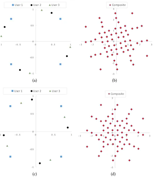
em-ploying 4-QAM. (a) Superimposed component constellations of EP users with phase allocations ofβ1= 0◦, β2= 18◦, β3= 35◦. (b) Composite constellation of EP users. (c) Superimposed component constellations of UP users with UP and phase allocations of D1 = 1.0, D2 = 0.9, D3= 0.9andβ1 = 0◦, β2 = 52◦, β3=
72◦, respectively. (d) Composite constellation of UP users. . . 66
3.4 Superimposed component and composite constellation of two users employing variable component constellations. (a) Users 1 and 2 employing BPSK and 4-QAM, respectively, producing 8-QAM composite constellation. (b) Users 1 and 2 employing BPSK and 8-QAM, respectively, producing 16-QAM composite con-stellation. (c) Users 1 and 2 employing BPSK and 16-QAM, respectively, produ-cing 32-QAM composite constellation. (d) Users 1 and 2 employing 4-QAM and 8-QAM, respectively, producing 32-QAM composite constellation. (e) Users 1 and 2 employing 6-QAM and 16-QAM, respectively, producing 64-QAM compos-ite constellation (f) Users 1 and 2 employing 8-QAM and 16-QAM, respectively, producing 128-QAM composite constellation . . . 69 3.5 LTE uplink structure (top) compared to UL-NCPr uplink structure (bottom);
CPP-Common periodic pilot, PUSCH- Physical uplink shared channel, SRS-Sounding reference signal, RS- reference signal, PUCCH- Physical uplink control channel 72
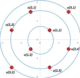
3.6 Ring format (R, J) for three BPSK component signals combined to form 8-QAM composite constellation . . . 78 3.7 UL-NCPr MATLAB simulation Model . . . 79 3.8 Two user UL-NCPr EP and UP compared to single user in SC-FDMA employing
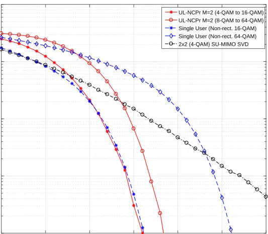
4-QAM with and without channel inversion, and MIMO 2x2 spatial multiplexing with ML and SIC detection schemes . . . 81 3.9 Two user UL-NCPr with users employing 4-QAM and 8-QAM component
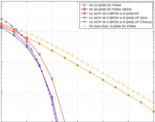
con-stellations, respectively. This is compared to single user in SC-FDMA employing 4-QAM with channel inversion, and a 2x2 MIMO SM SVD with CSIT&R . . . . 82 3.10 Three user UL-NCPr EP and UP compared to single user SC-FDMA employing
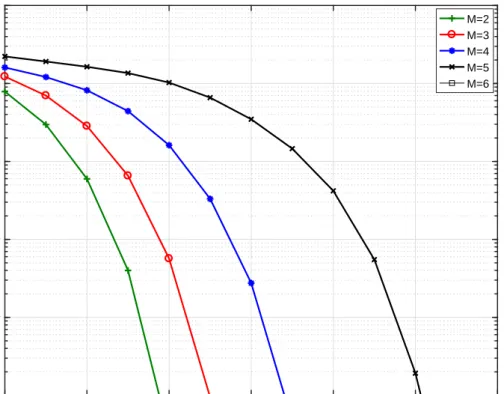
8-QAM with and without channel inversion schemes . . . 83 3.11 BER performance of UL-NCPr UP system for two to five users employing BPSK
component constellations using the power and phase allocations given in Table 3.4 84 3.12 Two user capacity region for UL-NCPr compared to PD-NOMA and OFDMA
schemes. The power allocations for UL-NCPr and PD-NOMA are given in Table 3.4. OFDMA uses equal power. The variance is set to unity i.eσ2= 1. PD-NOMA
and OFDMA employ SIC while UL-NCPr joint detection . . . 85 3.13 Constellation constrained capacity of two users in UL-NCPr each employing BPSK,
compared with conventional PD-NOMA, a single user OMA and Shannon limit Gaussian MAC as upper bound . . . 86 3.14 Constellation constrained capacity of two users in UL-NCPr each employing
4-QAM, compared with conventional PD-NOMA and a single user OMA . . . 87 3.15 Two user UL-NCPr shannon capacity compared with conventional PD-NOMA
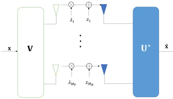
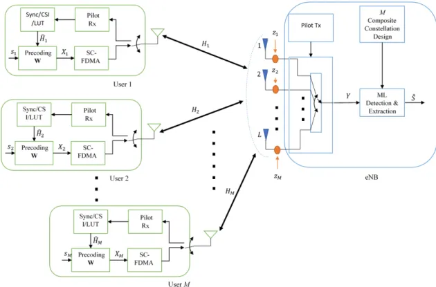
3.16 Constellation constrained capacity of three users in UL-NCPr each employing BPSK, compared with conventional PD-NOMA, a single user OMA and Shannon limit Gaussian MAC as upper bound . . . 89 4.1 System Model of the proposed downlink NOMA with constellation preforming
scheme. The figure shows the eNB equipped with a single antenna broadcasting preformed superimposed data to multipleM users also equipped with a single
antenna. The channel and noise are also illustrated. It is assumed the eNB trans-mits onN orthogonal subcarriers. . . 94
4.2 Superimposed component and composite constellation of three users each em-ploying 4-QAM. (a) Superimposed component constellations of PD-NOMA users with power allocations of D1 = 0.1P,D2 = 0.2P,D3= 0.7P. (b) Superimposed
component constellations of NCPf users with power and phase allocations of D1= 0.2P,D2= 0.2P,D3= 0.6P andβ1= 65, β2= 5, β3= 0, respectively. . . . 98 4.3 Superimposed component and composite constellation of two users employing
variable rate BPSK and 4-QAM. (a) Superimposed component constellations of PD-NOMA users with power allocations of D1= 0.4P,D2= 0.6P. (b)
Superim-posed component constellations of NCPf users with power and phase allocations of D1= 0.3P,D2= 0.7P andβ1= 43, β2= 0, respectively. . . 99
4.4 Superimposed component and composite constellation of two users employing variable rate 4-QAM and 8-QAM. (a) Superimposed component constellations of PD-NOMA users with power allocations of D1= 0.4P,D2= 0.6P. (b)
Superim-posed component constellations of NCPf users with power and phase allocations of D1= 0.3P,D2= 0.7P andβ1= 43, β2= 0, respectively. . . 100 4.5 NCPf simulation Model . . . 102 4.6 BER vs Eb/No performance of 2-user NCPf system compared to single user OMA
4.7 BER vs Eb/No performance of 3-user NCPf system compared to single user OMA. 104 4.8 2-user rate region illustrating the performance of NCPf compared to OMA and
PD-NOMA. The variance is set to unity i.e σ2 = 1. PD-NOMA and OFDMA
employ SIC while UL-NCPr joint detection . . . 105 4.9 2-user constellation constrained capacity performance for NCPf, compared to
OMA and PD-NOMA with the users employing BPSK component constellations, respectively. Shannon bound is included for comparison. . . 106 4.10 2-user constellation constrained capacity performance for NCPf, compared to
OMA and PD-NOMA with the users employing 4-QAM component constella-tions, respectively. Shannon bound is included for comparison. . . 107 4.11 3-user constellation constrained capacity performance for NCPf, compared to
OMA and PD-NOMA with the users employing BPSK component constellations,respectively. Shannon bound is included for comparison. . . 108 5.1 System Model of the proposed NOMA Constellation Preforming with Receive
Diversity scheme. The figure shows the eNB with a single antenna broadcasting preformed superimposed data to multipleM users equipped withKmantennas.
The channel and noise are also illustrated. It is assummed the eNB transmits on
N orthogonal subcarriers. . . 112
5.2 System Model of the proposed Constellation Preforming with Distributed Trans-mit Antenna Diversity. The figure shows the eNB with L antennas
broadcast-ing preformed superimposed data to multiple M users equipped with a single
antenna. The channel and noise are also illustrated. It is assummed the eNB transmits onN orthogonal subcarriers. . . 114
5.3 System Model of the proposed MIMO NOMA constellation preforming with spa-tial multiplexing and diversity scheme. The figure shows the eNB withL
anten-nas broadcasting preformed superimposed data to multiple M users equipped
withKmantennas. The channel and noise are also illustrated. It is assumed the
eNB transmits onN orthogonal subcarriers. . . 116
5.4 System Model of the proposed MIMO with group layered NOMA constellation preforming scheme. The figure shows the eNB with L antennas broadcasting
grouped and preformed superimposed data to multipleM users. The channels
are also illustrated. It is assumed the eNB transmits onN orthogonal subcarriers. 120
5.5 NCPf-RD simulation Model . . . 127 5.6 NCPf-DTAD simulation Model . . . 128 5.7 NCPf-SMD simulation Model . . . 129 5.8 Average BER vs Eb/No performance of 2-user NCPf-RD and NCPf-DTAD scheme
compared to single user OMA and 2-user PD-NOMA employing SIC. . . 131 5.9 2-user Shannon capacity performance for NCPf-RD. . . 132 5.10 2-user Shannon capacity performance for NCPf-DTAD. . . 133 5.11 2-user Shannon capacity performance for NCPf-SMD, compared to MIMO SM
employing SVD and BD. . . 134 5.12 4-user Shannon capacity performance for GL-NCPf, compared to 4x4 MIMO with
CSIT&R upper bound . . . 135 6.1 Example of coordinating femtocells . . . 142 6.2 Example ofJ CoMP-JCP downlink processing . . . 143
6.3 CoMP-JCP simulation Model . . . 153 6.4 BER vs Eb/No performance ofJ= 2CoMP-JCP compared with a 2x2 single user
constel-6.5 BER vs Eb/No performance ofJ= 3CoMP-JCP compared with a 3x3 single user
MIMO scheme employing SVD and single user employing the composite constel-lation in a point-to-point in additive white noise scheme. . . 156 6.6 Shannon capacity performance ofJ = 2CoMP-JCP compared with a 2x2 single
user MIMO scheme employing SVD, and single user in a point-to-point in addit-ive white noise scheme. . . 157 6.7 Shannon capacity performance ofJ = 3CoMP-JCP compared with a 3x3 single
user MIMO scheme employing SVD, and single user in a point-to-point in addit-ive white noise scheme. . . 158 6.8 Total power spent on precoding for4,16and64-QAM CoMP-JCP-ACS withK=2
andJ=50. We assumeEs/N owhereEs=ρEb is the symbol energy,ρthe
num-ber of bits-per-symbol,Ebthe energy per-bit, andNothe AWGN noise with the
variance defined asσ2= 1. We evaluate forρ= 2,4and6for4,16and64-QAM,
respectively. . . 159 6.9 Total power spent on precoding for8and64-QAM CoMP-JCP-ACS withK=3 and
J=50. We assumeEs/N owhereEs=ρEb is the symbol energy,ρthe number of
bits-per-symbol,Ebthe energy per-bit, andNothe AWGN noise with the variance
defined asσ2= 1. We evaluate forρ= 3and6for8and64-QAM, respectively. 160
6.10 Probability density function plot of the highestK= 2interfering CeNB channels
as a function of total availableJ CeNBs. A Rayleigh fading channel withℵ(0,1) is given as reference. (a)K = 2selected CeNBs out ofJ = 3. (b)K = 2selected
CeNBs out ofJ= 10. (c)K= 2selected CeNBs out ofJ= 20. (d)K= 2selected
CeNBs out ofJ= 30. (e)K= 2selected CeNBs out ofJ = 40. (f)K = 2selected
CeNBs out ofJ = 50. The plots assume the channels are ordered in decreasing
6.11 BER vs Eb/No performance of CoMP-JCP-MCA with each CeNB employing BPSK, compared with a single user employing 4-QAM and 2x2 MIMO SM. . . 162
Chapter 1
Introduction
1.1
Motivation
Wireless mobile communication systems have become evermore crucial in everyday life and a key factor in human and economic development. Nowadays, most aspects of human activities are tied to mobile internet services such as video streaming, social-izing, business related activities and other modern life dependent services. Furthermore, the emergence of new technologies such as Machine-to-Machine (M2M) systems, ultra high definition (UHD) 4K videos, real-time interactive services and cloud computing has transformed mobile devices from voice-data-telephony circuit switched devices to an all IP dependent devices. As a result, the growth of global mobile data traffic is expected to keep increasing aggressively. Therefore, efficient use of the limited available spectrum is a crucial and challenging task to meet the increasing number of connected devices and their demands. Furthermore, power and complexity constraints add more difficulties on the development of next generation mobile systems.
number of users that can be accommodated within a cell needs to be significantly in-creased without necessarily increasing the number of Base Stations (BS). Secondly, fu-ture generation data and multimedia traffic require a high data rate in order of hun-dreds of Mb/s for high mobility users and up to Gb/s for low mobility or fixed users with the end-to-end latencies not exceeding 5 ms. Thirdly, the expected increase in data traffic should not have a significant cost on battery life. Finally the cost of delivering high quality services and high data rate should be kept affordable. Therefore, fulfilling these requirements requires maximising bandwidth efficiency, exploiting all available degrees of freedom (time, frequency, power and space), minimising power consumption and utilization of fading and interference which would lead to improved performance and capacity.
To address these challenges, the latest and evolving wireless networking standards such as the Worldwide Interoperability for Microwave Access (WiMAX), Third Genera-tion Partnership Project (3GPP), represented by Long Term EvoluGenera-tion advanced (LTE)-Advanced and the ITU’s IMT-(LTE)-Advanced, all envisage the concurrent deployment of a number of compatible technologies in the physical and multiple access layers.
One of these key technologies is multi-carrier Multiple Access Schemes (MAS) which are based on Orthogonal Frequency Division Multiplexing (OFDM) such as Orthogonal Frequency Division Multiple Access (OFDMA) and Single Carrier OFDMA (SC-OFDMA). These schemes enable efficient as well as robust performance against fading by convert-ing the channel bandwidth into many parallel, overlappconvert-ing and orthogonal flat fadconvert-ing sub channels.
To further improve the spectral efficiency, Non-Orthogonal Multiple Access (NOMA) has recently been proposed for the future5th Generation (5G) mobile systems to
comple-ment the existing orthogonal MAS [1] [2]. NOMA utilizes the principles of superposition coding where multiple users are scheduled in the power domain such that they share the same time/frequency resource simultaneously. The combined received signals are detec-ted by employing Successive Interference Cancellation (SIC), which inherently, requires large power separation between users for successful detection. This increases the over-all system capacity, however, as the users transmit at different power levels, throughput fairness is poor for the weaker power users.
Another technology that is envisioned to be used concurrently with OFDMA and NOMA is Multiple-Input-Multiple-Output (MIMO) communication which exploits the rich scattering environment and the availability of multiple antennas at both the trans-mitter and receiver to allow many users to access the network, simultaneously achieving linear increase in system capacity without consuming extra bandwidth or power. In ad-dition to its capacity gain, MIMO can provide spatial diversity to improve the Bit Error Rate (BER) performance. However MIMO is limited by the number of receive antennas, the amount of feedback required for scheduling and precoding, and by channel cor-relations due to insufficient antenna separation at the terminals and/or poor scattering environment. As a result, the sum rate capacity and BER performance are significantly degraded. Moreover the cost of employing multiple Radio Frequency RF chains remains high.
1.2
Research Aims and Objectives
• To design low-feedback and spectrally efficient non-orthogonal multiple access schemes based on the principle of signal superposition.
non-orthogonal multiuser based on superposition coding.
• Design high-rate spatial multiplexing and diversity schemes that utilize less trans-mit antennas without comprising their transmission rate.
1.3
Contributions of the Thesis
A number of contributions have been made in this work; below is a summary of main findings and contributions:
1. A novel NOMA signal design called Uplink NOMA With Constellation Precoding (UL-NCPr) is proposed. The goal of the scheme is to allow simultaneous utiliza-tion of the same time/frequency network resources. This is achieved by designing component signals in both power and phase domain such that as many users form a single and uniquely decodable composite signal. As the composite constellation is as that of a single user transmitting that same constellation, multiple access in-terference can be viewed as absent, which allows multiple users to transmit at their full rates. This relaxes the large power separation required for NOMA based on power domain superposition. Furthermore, this departs from user-specific power control and successive interference cancellation receivers, to a new approach that optimises power and phase domain precoding utilizing only a small common pilot and without the need for Channel State Information (CSI) to decode the users sig-nals. Furthermore, the power gain achieved by the sum of the component signals maximizes the sum rate.
2. A novel downlink NOMA constellation design scheme called NOMA with Con-stellation Preforming (NCPf) where the power and phase domain are utilized to
improve link capacity in the distant-dependant based signal superposition. The objective is based on maximizing the minimum Euclidean distance of composite received signals to resolve the detection ambiguity. The simplicity and compatib-ility of these methods enable integration into various existing and future wireless communication systems. The key contributions of the proposed technique are:
• Efficient utilization of a single transmitter to transmit multi-user signals on the same time/frequency resource. This is in comparison to spatial multi-plexing schemes where each stream requires separate RF chains.
• Interference elimination by multi-user signal superposition. The users see the received signal as a single composite signal without interference from other users’ signals. Consequently, increased capacity without significant loss in error performance is achieved.
• Improved signal reliability from spatial diversity without incurring the sub-stantial increase in both complexity and overheads.
• A novel Spatial Multiplexing (SM) and Diversity (SMD) preforming scheme called NCPf-SMD, where the total number of independent multi-user streams are more than the number of available transmit antennas, compared to the required one-to-one antenna-stream relationship in traditional MIMO SM. • Significant reduction in the cost of Radio Frequency (RF) chains associated
with transmit antennas, while still achieving spatial multiplexing and di-versity gains.
• Reduction in signalling overheads, maximize system capacity without em-ploying channel precoding.
• A high link capacity scheme called Group Layered NCPf (GL-NCPr), were less transmit antennas are utilized to serve a high number of users without the effect of co-channel interference. This results in a highly spectrally efficient scheme reducing the number of transmit antenna used for communication and at the same time, increase the number of users served.
3. A novel Coordinated Multipoint (CoMP) spatial multiplexing scheme is proposed, where inter-cell interference is utilized to improve spectral efficiency to a user with a single receive antenna. The aim of the scheme is to eliminate inter-cell interfer-ence by coordinating then interferers with useful signals such that they combine and serve a user even with a single antenna. Maximum likelihood detection is employed at the receiver to provide optimum signal reliability and performance. Furthermore, we propose two power control schemes as follows:
• Coordination to eliminate inter-cell interference and improve spectral effi-ciency by actively selecting the strongest interferers to the user.
• Reduction in cross-layer interference by adapting the transmission power to the average channel gains. Thereby allowing increased network capacity without the consequence of co-channel interferences.
1.4
Outline of the Thesis
The thesis is organized as follows. Introduction to LTE, technical background theory and literature review of the related work are presented in Chapter 2. The principles and features of the traditional wireless multiple access techniques are presented. Next, an overview and review of MIMO communication system is carried. We end the chapter
with the requirements and challenges of the proposed future 5G.
In Chapter 3, a novel NOMA UL-NCPr is proposed. First, the related work and mo-tivation is presented before introducing the constellation design principles of UL-NCPr. Next a detailed description of UL-NCPr system model is given. This includes signal model, the constellation design, antenna selection and Joint Maximum Likelihood (JML) detection. In the constellation design, the design objectives and considerations, require-ments and search algorithm are presented. Next is the signalling and synchronization which include the common periodic pilot and synchronization acquisition. A detailed performance analysis is carried out before ending the chapter with simulation modelling and results to evaluate the performance of the scheme.
Chapter 4, the constellation design principle is proposed in a downlink broadcast scheme. We introduce and present the design principle. Next, a detailed system model were the constellation design, search algorithm and JML detection are presented. A detailed performance analysis is carried out. Finally, the system model and simulation results are presented.
Chapter 5 presents four downlink multi-antenna constellation schemes. First, two spatial diversity schemes in two sections (Receive and transmit diversity) are described. Next, our novel NOMA MIMO with spatial multiplexing and diversity scheme is in-troduced. The system model along with two detection methods are presented . Next, performance analysis on all the four schemes are carried out. Finally, the simulation models results are presented and discussed
Chapter 6 introduces our novel CoMP spatial multiplexing scheme. First, the scheme is introduced followed by the motivation and related works. The principles of joint con-stellation processing is presented. Next, the joint concon-stellation precessing system model,
maximum like hood detection are transmission procedures are presented. To reduce the total power spent on precoding, an active cell selection scheme is presented. The sys-tem model and procedures are described. Next, a cross-layer interference minimization scheme is presented where the transmission power is adapted to the mean channel gain. The system model and procedures are described. Next, the simulation model of the schemes are described followed by the presentation and discussions of the simulation results.
Finally, Chapter 7 concludes the thesis, with a summary of main findings and con-tributions and some discussion on future work.
Chapter 2
Technical Background
2.1
LTE and LTE-Advanced
2.1.1
Introduction
The evolution of 3rd Generation (3G) into 4th Generation (4G) LTE mobile systems is driven by the emergence and enhancements of new technologies in mobile communic-ation systems. These were developed due to the need for more efficient utilizcommunic-ation of the limited available spectrum, increased throughput, the competition between mobile operators and challenges from other mobile technologies [3, 4, 5].
One of the key drivers of 4G is the rapid increase in the number of users and devices accessing the internet. This required future mobile systems to support Internet Protocol (IP) based services. As earlier generation mobile systems were built for circuit switched services, primarily voice, the need for more efficient and back-compatible end-to-end IP networks became the core operational principle for 4G systems. The mobility and roam-ing capabilities of mobile devices also allows mobile network operators create targeted services to end users.
IP technology enables a range of services with different requirements. The main design requirements for a radio interface supporting a variety of services are:
• Data rate: Many services with lower data rates such as voice are important and still occupy a large part of a mobile networks overall capacity. However, the ever increasing demand for higher data rates for web browsing, video streaming and file transfer pushes the peak data rates for mobile systems from Mbit/s for 3G to Gbit/s for 4G.
• Capacity: Not only the peak data rates provided to the end-user that are of im-portance, but also the total data rate that can be provided on average from each deployed base station site and per hertz of licensed spectrum.
• Delay: Real-time and interactive services such as conference calls, gaming, health-care related applications e.t.c have requirements for very low latency, thus making it a primary design target.
• Cost/Energy: As the number of connected devices and data consumption increases, so does the network energy footprint. Therefore, minimizing cost-per-bit and joule-per-bit is essential to improve operational efficiency and consumer satisfac-tion.
2.1.2
LTE Architecture
The LTE architecture of both the Radio-Access Network (RAN) and the Core Network (CN) together are referred to as the LTE RAN and the Enhanced packet Core (EPC), respectively, as illustrated in Figure 2.1. The RAN is responsible for all radio-related functionality including, scheduling, radio-resource handling, multi-antenna schemes,
Figure 2.1: LTE high level network architecture
retransmissions and coding. The EPC is responsible for back-end network functions such as authentication, charging functionality, and the setup of end-to-end connections. The separation of RAN with EPC allows for several radio-access technologies to be served by the same core network, making it back compatible with earlier generation mobile systems [6, 7].
The LTE RAN provides one or more radio bearers to which IP packets are mapped ac-cording to their Quality-of-Service requirements. These include the Packet Data Conver-gence Protocol (PDCP) for compression and security related operations, Radio-Link Con-trol (RLC) for segmentation/concatenation, retransmissions, duplicate detection, and in-sequence delivery to higher layers, Medium-Access Control (M-AC) for the multiplexing of logical channels, hybrid-Automatic Requests (H-ARQ) retransmissions and schedul-ing, Physical Layer (PHY) for coding/decodschedul-ing, modulation/demodulation, multi-antenna mapping.
2.1.3
EUTRAN-NodeB (eNB)
The LTE radio-access network uses a logical node base station architecture known as the eNodeB (eNB). The eNB is responsible for all radio-related functions in one or multiple
cells. The eNB is connected to the EPC by means of the S1 interface for both the user and control planes. Multiple eNBs are connected to each other via the X2 interface which provides functions such as multi-cell Radio Resource Management (RRM) to provide Inter-Cell Interference Coordination (ICIC). As the eNB is a logical and not a physical implementation, it allows operators to deploy scaled down versions to increase coverage and capacity. These are known as Macro (Urban:>100m), pico (Dense:<100m) and femto
(Indoor:<50m) cells [6].
2.1.4
Physical transmission
The physical layer is responsible for coding, physical-layer hybrid-ARQ processing, mod-ulation, multi-antenna processing, synchronization and resource mapping. It also handles mapping of transport channels to physical channels in the form of Transport Blocks (TB) at each Transmission Time Interval (TTI). Data transmission in downlink and uplink use the Down Link Shared (DL-SCH) and Uplink Shared (UL-SCH) transport channels, re-spectively. There are at most two transport blocks per TTI on a DL-SCH or UL-SCH. There are also physical control channels known as L1/L2 control channels [8].
The physical-channel types defined in LTE include [9]:
• The Physical Downlink Shared Channel (PDSCH) is the main physical channel used for downlink transmission of unicast data and paging information.
• The Physical Uplink Shared Channel (PUSCH) is the uplink counterpart to the PDSCH.
• The Physical Broadcast Channel (PBCH) carries part of the system information, required by the terminal to access the network.
• The Physical Multicast Channel (PMCH).
• The Physical Downlink Control Channel (PDCCH) is used for downlink control information used for scheduling related operations.
• The Physical Hybrid-ARQ Indicator Channel is used for acknowledgements and retransmission requests.
• The Physical Control Format Indicator Channel provides the terminals with in-formation necessary to decode the set of PDCCHs.
• The Physical Uplink Control Channel (PUCCH) is used by the terminal to send channel-state information for downlink channel-dependent scheduling, and for requesting resources to transmit uplink data.
• The Physical Random-Access Channel (PRACH) is used for random access.
• Primary Synchronization Signal/Channel (PSS) and Secondary Synchronization Signal/Channel (SSS) are used for radio frame synchronization.
2.1.4.1 Frame Structure
LTE transmissions are organized into Time Domain Duplex (TDD) (Figure 2.2) or Fre-quency Domain Duplex (FDD) (Figure 2.3) radio frames10ms in length, each of which
is divided into ten equally sized subframes of length1ms. Each subframe consists of two
equally sized slots of length0.5ms, with each slot consistingK = 7OFDM symbols
in-cluding Cyclic Prefix (CP). The LTE OFDM subcarrier spacing is15kHz for both
down-link and updown-link which was chosen to carefully balance the overhead from cyclic prefix against sensitivity to Doppler spread and other types of frequency errors. The subcarrier spacing, assuming Fast Fourier Transform (FFT)-based implementation, translates to a
Figure 2.2: LTE time domain frame architecture
sampling rate and timefs= 1500·NFFT andTs= 1/(15000·NFFT), respectively, where
NFFT is the FFT size [10].
The smallest physical resource in LTE is called Resource Element (RE), which consists of one subcarrier during one OFDM symbol. The RE are grouped into Resource Blocks (RB)NRB, where each RB consists of 12 consecutive subcarriers in the frequency domain and one0.5ms (7OFDM symbols each with cyclic prefix) slot in the time domain. Each
RB thus consists of 7·12 = 84 RE’s. The bandwidths and FFT sizes defined in LTE
standard are shown in Table 2.1.
Table 2.1: LTE resource parameters defined in LTE standard
Channel bandwidth (MHz) 1.4 3 5 10 15 20
Number of resource blocks(NRB) 6 15 25 50 75 100
Number of subcarriers(NSC) 72 180 300 600 900 1200
IFFT (Tx)/FFT (Rx) size(NFFT) 128 256 512 1024 1536 2048
Sample rate (MHz) 1.92 3.84 7.68 15.36 23.04 30.72
Figure 2.3: LTE time and frequency resource block 2.1.4.2 Synchronization
The PSS and SSS are used for radio frame synchronization. PSS are based on three 62-bit Zadoff-Chu sequences which are mapped to 72 active sub carriers in slot 0 and 10 in FDD, and slot 1 and 11. SSS is similar to PSS, however, they are made up of 62-bit ’m-sequence’ scrambling sequences.
The eNB actively measures and sends a timing advance and frequency offset com-mands based on the difference between the received PUSCH, PUCCH and SRS. The re-ceived PSS and SSS commands are decoded by comparing with the three PSS sequences so as to obtain the sequence assigned to the cell, the Cell ID an group, as well as the primary synchronization offset. This process is repeated every 5 ms. The Cell ID is used to determine the pseudo-random sequence used for generating the reference signal in the cell. Once established, the (MIB) and (SFN) can be determined.
2.1.4.3 Uplink Physical-Layer Transmission
The LTE M-AC scheduler allocates a set ofNRBpairs which spanK = 14OFDM symbols in time (one subframe) to be used for the uplink transmission on the PUSCH physical channel. Two symbol periods are used for uplink demodulation reference signals for CSI and are thus not available for transmission. Furthermore, one additional symbol may be reserved for Sounding Reference Signals (SRS). SRS can also be used to estimate the downlink CSI assuming uplink/downlink reciprocity. This is especially of interest for TDD, where transmissions in downlink and uplink are on the same carrier frequency [11].
K blocks ofN FFT-precoded symbols are mapped to the basic OFDM time-frequency
grid, whereN = 12·NRB is the assigned bandwidth in number of subcarriers. Mapping
of the FFT-precoded signal to frequency-contiguous resource elements is preferred to retain good cubic-metric properties of the uplink transmission.
2.1.4.4 Downlink Physical-Layer Transmission
For downlink transmissions, up to two transport blocks of dynamic size are delivered to the physical layer and transmitted over the radio interface for each component car-rier, depending on the configuration of the multi-antenna transmission scheme em-ployed. The modulation schemes supported for the LTE downlink are QPSK, 16QAM, and 64QAM, respectively [12, 9, 13].
The modulation symbols are first mapped to NL layers, corresponding to the num-ber of antennas. The layers are then mapped to the antenna ports by means of the pre-coder functionality. The prepre-coder relies on the Cell-Specific Reference Signals (CRS) for channel estimation for which there are at most four in each RB. This precoder/antenna
mapping can be described by a precoder matrixWof sizeL×NL, whereLis the number
of antenna ports. Thus the output of the precoder can be expressed as
xi=wisi i∈L (2.1)
where xi is the precoded symbol at the i-th antenna output, wi is the i-th precoding
weight, andsiis thei-th precoder input symbol. The antenna mapping can be configured depending on multi-antenna transmission scheme employed. These include transmit diversity, beam-forming and spatial multiplexing. The symbols of each antenna port are subsequently applied to the OFDM modulator [14].
Two classes of precoders are defined in LTE. These are Closed-Loop (CL) and Open Loop (OL) precoding, respectively. In case of CL precoding, the terminal selects and feeds back a suitable transmission rank and corresponding precoder matrix in the form of a Rank Indication (RI) and a Precoder-Matrix Indication (PMI), respectively. To limit the signalling overheads, only a limited set of codebook precoder matrices are defined for each transmission rank for a given number of antenna ports. OL precoding does not rely on any precoding. The precoder matrix is selected in a predefined and deterministic way known to the terminal in advance. The is especially important in high mobility scenarios where feedback is difficult [15, 16].
Similar to codebook-based precoding, non-codebook-based precoding is only applic-able to DL-SCH transmission
2.1.5
Coordinated Multi-Point (CoMP)
CoMP is a technique introduce in LTE-A that enables the dynamic coordination of trans-mission and reception over different eNB’s. The technique enables the
Inter-Channel-Interference (ICI) of neighbouring eNB’s to be turned into useful signal, and thus results in improved overall system performance as well as efficient utilisation of the network. This is especially advantageous to cell edge users, who not only receive weaker signals from their serving eNB, but also high interferences from neighbouring eNBs. CoMP is divided into Joint Processing (JP) (Figure 2.4) and Coordinated Scheduling/Beamforming (CS/CB) (Figure 2.5) for both uplink and downlink [17, 18].
The downlink JP, data is transmitted to the terminal simultaneously from different eNBs so as to improve the received signal quality and strength, or actively cancel inter-ference from transmissions that are intended for other terminals. This however, places a high demand onto the backhaul network because the data to be transmitted are shared to all participating eNBs. For downlink CS/CB, data to a single terminal is transmitted from one eNB, however, scheduling decisions are coordinated to control the interference. This reduces the backhaul signal in that only scheduling decisions are shared [19, 20].
Figure 2.4: Joint Processing in Coordinated Multipoint
Figure 2.5: Coordinated Scheduling/Beamforming in Coordinated Multipoint
For uplink JP, multiple antennas at different eNBs are utilized to form a virtual an-tenna array. The signals received at the eNBs are then combined and processed to
pro-duce the final output signal. Uplink CS/CB operates by coordinating the scheduling decisions amongst the eNBs to minimise interference.
2.2
Multiple Access Techniques
Multiple Access allows multiple users to share a communication channel efficiently. The users transmit their signals independently to a common receiver via their respective channels. The transmissions must be within the total system bandwidth with individual user power constraints. Typically, the user transmissions are coordinated and synchron-ized by the base stations, such that the received signals are received coherently. MAS can be classified into two Orthogonal Multiple Access (OMA) and NOMA [21, 22, 23].
2.2.1
Orthogonal Multiple Access (OMA) Schemes
In OMA, multiple users transmit on orthogonal channels such that there is no interfer-ence in the users signal waveform. Thus, the receiver detects the signal for each user without interference from other users with the error performances similar to that of a single user. The total system resource/bandwidthW in time and frequency is divided
into M frequency channels between the M users to ensure orthogonality. Examples
of OMA techniques include time division multiple access (TDMA), frequency division multiple access (FDMA) (Figure 2.6), orthogonal division multiple access (OFDMA) and other MAC scheme which assign orthogonal signal waveforms.
2.2.1.1 Time Division Multiple Access (TDMA)
Time Division Multiple Access (TDMA) allows each user to transmit using the entire available bandwidth for a portion of the time [24]. Each frequency channel is divided
Figure 2.6: Orthogonal TDMA and FDMA resource allocation
into a number of periodically recurring time slots and multiple users are allocated a number of time slots which can vary according to their rate requirements. The number of slots in a frame, how many time slots are assigned to each user, and how this assign-ment is performed, depends on a number of factors such as permissible delay, available bandwidth, modulation technique etc.
2.2.1.2 Frequency Division Multiple Access (FDMA)
Frequency Division Multiple Access (FDMA) is the most classic MAC scheme used in mobile communications systems. The available system bandwidthW is divided intoM
equal narrow band frequency channels servingMusers simultaneously where each user
is allocated its exclusive channel. Frequency spacing between the user channels is re-quired to minimize inter-channel interference caused by the non-linear effects of power amplifiers, operating near saturation which spread the signal bandwidth and generate inter-modulation frequencies [24, 4].
The basic challenges of classic FDMA are the requirement ofM modulators and
de-modulators at the base station to serveM users simultaneously, which leads to
rate requirements due to the fixed allocation of narrowband channels. Thirdly, it suffers bandwidth wastage where no sub-channel is reallocated to other users if it is not in use by the assigned user [3, 25].
2.2.1.3 Orthogonal Frequency Division Multiplexing (OFDMA)
OFDM [26, 27] is a narrowband OMAS scheme used in 4G networks. In OFDM, the signals to be transmitted are mapped onto several parallel orthogonal sub-carriers (Fig-ure 2.7). The orthogonality between subcarriers is ens(Fig-ured by spacing the subcarriers by n/Ts, where Ts is the symbol time and n is a non-zero integer usually chosen as one. Guard intervals called CP are added to each OFDM symbol to mitigate ICI. Fur-thermore, the bandwidth of each sub-carrier is narrower than the coherence bandwidth of the channel, which ensures flat fading in an otherwise frequency-selective channel. Practical implementations of OFDM is performed with a more efficient and faster Inverse Fast Fourier Transform (IFFT) for modulation, while fast fourier transform (FFT) is used for demodulation.
OFDMA [26, 28, 29] is a hybrid combination of FDMA and OFDM. It is currently used in wireless LAN, WiMAX (IEEE 802.16), and LTE downlink systems. The system bandwidth is divided into many sub-channels and each user is allocated multiple ded-icated sub-channels, allowing M users transmit simultaneously. The number of
sub-carriers allocated to each user is flexible dependent on its rate and QoS requirement. Additionally, sub-carrier allocation to different users can be either adaptive tor fixed [30, 31, 32, 33, 34, 35]. Fixed sub-carrier allocation does not adapt to users’ channel conditions and remain unchanged throughout the communication session leading to a simpler implementation without incurring high overheard. Furthermore, the users can be allocated adjacent subcarriers, which simplifies frequency and time synchronization
Figure 2.7: OFDMA resource allocation and modulation
on the expense of vulnerability to deep fading, or separated by more than the coherent bandwidth of the channel to exploit maximum frequency diversity, at the expense of a minimum separation between sub-carriers from different users requiring strict cross-user synchronization to avoid ICI.
Adaptive sub-carrier allocation dynamically allocates sub-carriers to users based on their channel condition so as to optimize some performance criteria.
The main challenges with OFDMA is that it suffers from a high Peak-to-Average Power Ratio (PAPR) which leads to inefficient operation of power amplifiers [36, 11, 31]. This is especially critical in uplink where user transmit powers are limited Secondly, OFDM is very sensitive to errors in time and frequency synchronization which leads to frequency and phase offset causing ICI and ISI.
2.2.1.4 Single Carrier-Frequency Division Multiple Access (SC-FDMA)
SC-FDMA can be described as normal OFDM with a FFT-based precoding to reduce the PAPR of the transmitted signal envelope [37, 38, 39, 40, 41, 42, 43, 44]. This is also known as DFTS-OFDM. A block ofOmodulation symbols from some modulation alphabet are
first applied to a size-N DFTNDFT. The output of the DFT is then mapped to consecut-ive subcarriers of an OFDM modulator where a size-K IFFTKIFFT is implemented with
KIFFT > NFFT. The unused IFFT subcarriers are set to zero. This is illustrated in Fig-ure 2.8. A more computationally efficient radix-2IFFT processing,KIFFT = 2k, for some integer k is used in place of IFFT. Similar to normal OFDM, a cyclic prefix is inserted
for each transmitted block. When the FFT sizeM equals the IFFT sizeK, the FFT-IFFT
Figure 2.8: SC-FDMA resource allocation and modulation
processing would imply cancel each other out. However, whenMis smaller thanKwith
the remaining inputs to the IFFT set to zero, the output of the IFFT will be a signal with ‘single-carrier’properties such as low power variations which increase power amplifier efficiency, and a bandwidth that depends onM.
2.2.2
Non-Orthogonal Multiple Access (NOMA) Schemes
NOMA is a promising technology that aims to increase the system throughput and ca-pacity [45, 2, 46, 45, 47, 48]. NOMA allows multiple users to share time and frequency resources in the same spatial layer via simple linear superposition or code-domain mul-tiplexing. The interference in NOMA is made controllable by non-orthogonal resource allocation, at the cost of slightly increased receiver complexity, where SIC or ML is em-ployed. In OMA, although the orthogonally multiplexed users facilitates simple and interference-free Multi-User Detection (MUD) at receivers, it does not achieve the sum-rate capacity of a wireless system.
2.2.2.1 Power Domain NOMA (PD-NOMA)
PD-NOMA [2, 49, 50, 45, 1, 51, 52, 53, 48, 54] is a leading candidate for 5G multiple access. It is based on the principles of superposition coding where the transmitted signal is the sum of users’ signals in the power domain, as illustrated in Figure 2.9. The scheme exploits the received power differences due to the near-far effect between users to solve the problem of detection ambiguity. i.e. the weaker users are allocated more power compared to the stronger users. Thus, the larger the difference in power level of the users’signals, the better the performance which outperforms the orthogonal schemes.
Consider a two user system where user 1 and user 2 are located far and near an eNB. Their transmit powers are P1 and P2. The received signals for the downlink,ym[DL], and uplinky[U L] PD-NOMA systems can be expressed as
y[mDL]=hm( p P1x1+ p P2x2) +zm=hmx+zm (2.2) y[U L]=h 1 p P1x1+h2 p P2x2+z (2.3)