i
VFG6005 Series
VPN Firewall Gateway
User’s Guide
IP Addresshttp://192.168.10.1
Loginadmin
Password1234
Firmware Version 2.07
Edition 1, 5/2011
www.us.zyxel.com
ii
About This User's Guide
Intended Audience
This manual is intended for people who want to configure the VFG6005 Series using the Web Configurator. You should have at least a basic knowledge of TCP/IP networking concepts and topology.
Related Documentation
• Quick Start Guide
The Quick Start Guide is designed to help you get up and running right away. It contains information on setting up your network and configuring for Internet access.
• Supporting Disc
Refer to the included CD for support documents.
• ZyXEL Web Site
Please refer to www.us.zyxel.com for additional support documentation and product certifications.
User Guide Feedback
Help us help you. Send all User Guide-related comments, questions or suggestions for improvement to the following address. Thank you!
SUPPORT E-MAIL WEB SITE
iii
Customer Support
Please have the following information ready when you contact Customer Support:
Product model and serial number Warranty information
Date that you received or purchased your device
Brief description of the problem including any steps that you have taken before contacting the ZyXEL Customer Support representative
Support Email
0H[email protected]
Toll-Free
1-800-978-7222
Website
1Hwww.us.zyxel.com
Postal mail
ZyXEL Communications Inc.
1130 N. Miller Street,
Anaheim, CA 92806-2001
U.S.A.
iv
Document Conventions
Warnings and Notes
These are how warnings and notes are shown in this User‘s Guide.
Warnings tell you about things that could harm you or your device.
Note: Notes tell you other important information (for example, other things you may need to configure or helpful
tips) or recommendations.
Syntax Conventions
• The VFG6005 series may be referred to as the ―VFG‖, the ―device‖, the ―product‖ or the ―system‖ in this User‘s Guide.
• Product labels, screen names, field labels and field choices are all in bold font.
• A key stroke is denoted by square brackets and uppercase text, for example, [ENTER] means the ―enter‖ or ―return‖ key on your keyboard.
• ―Enter‖ means for you to type one or more characters and then press the [ENTER] key. ―Select‖ or ―choose‖ means for you to use one of the predefined choices.
• A right angle bracket ( > ) within a screen name denotes a mouse click. For example, Admin > Log means you first click Admin in the navigation panel, then the Log tab to get to that screen.
• Units of measurement may denote the ―metric‖ value or the ―scientific‖ value. For example, ―k‖ for kilo may denote ―1000‖ or ―1024‖, ―M‖ for mega may denote ―1000000‖ or ―1048576‖ and so on.
v
Icons Used in Figures
Figures in this User‘s Guide may use the following generic icons. The VFG icon is not an exact representation of your device.
vi
Safety Warnings
• Do NOT use this product near water, for example, in a wet basement or near a swimming pool.
• Do NOT expose your device to dampness, dust or corrosive liquids.
• Do NOT store things on the device.
• Do NOT install, use, or service this device during a thunderstorm. There is a remote risk of electric shock from lightning.
• Connect ONLY suitable accessories to the device.
• Do NOT open the device or unit. Opening or removing covers can expose you to dangerous high voltage points or other risks. ONLY qualified service personnel should service or disassemble this device. Please contact your vendor for further information.
• Make sure to connect the cables to the correct ports.
• Place connecting cables carefully so that no one will step on them or stumble over them.
• Always disconnect all cables from this device before servicing or disassembling.
• Use ONLY an appropriate power adaptor or cord for your device.
• Connect the power adaptor or cord to the right supply voltage (for example, 110V AC in North America or 230V AC in Europe).
• Do NOT allow anything to rest on the power adaptor or cord and do NOT place the product where anyone can walk on the power adaptor or cord.
• Do NOT use the device if the power adaptor or cord is damaged as it might cause electrocution.
• If the power adaptor or cord is damaged, remove it from the power outlet.
• Do NOT attempt to repair the power adaptor or cord. Contact your local vendor to order a new one.
• Do not use the device outside, and make sure all the connections are indoors. There is a remote risk of electric shock from lightning.
• Do NOT obstruct the device ventilation slots, as insufficient airflow may harm your device.
• Antenna Warning! This device meets ETSI and FCC certification requirements when using the included antenna(s). Only use the included antenna(s).
• If you wall mount your device, make sure that no electrical lines, gas or water pipes will be damaged.
Your product is marked with this symbol, which is known as the WEEE mark. WEEE stands for Waste Electronics and Electrical Equipment. It means that used electrical and electronic products should not be mixed with general waste. Used electrical and electronic
i
Table of Contents
2H
About This User's Guide ...
92Hii
3H
Document Conventions ...
93Hiv
4H
Safety Warnings...
94Hvi
5H
CHAPTER1
INTRODUCTION
...
95H1
6H
1.1
BENEFITS ...
96H1
7H
1.2
PACKAGE CONTENT ...
97H3
8H
CHAPTER2
HARDWARE INSTALLATION
...
98H4
9H
2.1
PANEL LAYOUT ...
99H4
10H
2.1.1 Front LEDs (left to right) ...
100H4
11H
2.1.2 Rear Panel (left to right) ...
101H5
12H
2.2 PROCEDURE FOR HARDWARE INSTALLATION ...
102H6
13H
2.2.1 Power On ...
103H6
14H
2.2.2 Setup LAN Connection ...
104H6
15H
2.2.3 Setup WAN Connection ...
105H6
16H
CHAPTER3
NETWORK SETTINGS FOR YOUR PC
...
106H7
17H
3.1 FOR WINDOWS XP USERS ...
107H7
18H
3.2 FOR WINDOWS 2000 USERS ...
108H9
19H
3.3 FOR WINDOWS 98/ME USERS ...
109H11
20H
3.4 FOR WINDOWS 7 USERS ...
110H13
21H
CHAPTER4
ACCESSING THE GATEWAY
...
111H15
22H
4.1 START-UP AND LOG-IN ...
112H15
23H
CHAPTER5
BASIC SETTINGS
...
113H16
24H
5.1 WAN SETUP ...
114H16
25H
5.1.1 DHCP (automatic IP address assignment) ...
115H18
26H
5.1.2 Static (Fixed IP address assignment) ...
116H18
27H
5.1.3 PPPoE (connected by username/password) ...
117H19
28H
5.1.4 Ethernet WAN MAC Address Clone ...
118H20
29H
5.1.5 Mobile WAN (connected by information related to what your ISP needs) ...
119H20
30H
5.1.6 HSPA+ Super Speed ...
120H23
31H
5.2 WAN DETECT ...
121H25
32H
5.3 LAN SETUP ...
122H26
33H
5.4 DHCP SERVER SETUP ...
123H27
34H
5.5 DDNS SETUP ...
124H28
35H
CHAPTER6
WIRELESS SETTINGS
...
125H30
ii
37H
6.1.1 Settings ...
127H30
38H
6.1.2 SSID Settings...
128H31
39H
6.1.3 WEP ...
129H32
40H
6.1.4 WPA Pre-shared Key / WPA2 Pre-shared Key ...
130H33
41H
6.1.5 WPA / WPA2 ...
131H34
42H
6.2 ADVANCED SETUP ...
132H35
43H
6.3 WPS – WIFI PROTECTED SETUP ...
133H37
44H
CHAPTER7
SECURITY SETTINGS
...
134H38
45H
7.1 FIREWALL SETUP ...
135H38
46H
7.2 ACCESS CONTROL LIST (ACL) SETUP...
136H40
47H
7.2.1 ACL Settings ...
137H40
48H
7.3 MAC ACCESS CONTROL SETUP ...
138H43
49H
7.4 OpenDNS SETUP ...
139H45
50H
7.4.1 OpenDNS Settings ...
140H45
51H
7.5 WEB FILTERING SETUP ...
141H46
52H
7.5.1 Added Web Filtering Rules ...
142H47
53H
7.6 VPN / PPTP SETUP ...
143H48
54H7.6.1 VPN / PPTP Settings ...
144H48
55H7.6.2 Add VPN / PPTP Rule ...
145H50
56H7.7 VPN / L2TP SETUP ...
146H51
57H7.7.1 VPN / L2TP Settings ...
147H51
58H7.7.2 Add VPN / L2TP Rule ...
148H52
59H7.8 VPN / IPsec SETUP ...
149H53
60H7.8.1 VPN / IPsec Settings ...
150H53
61H
7.8.2 Add VPN / IPsec Rule ...
151H54
62H
CHAPTER8
APPLICATIONS SETTINGS
...
152H56
63H
8.1 PORT RANGE FORWARD SETUP ...
153H56
64H
8.1.1 Port Range Forward Settings ...
154H57
65H
8.1.2 Add Port Range Forwarding Rule ...
155H58
66H
8.2 1-1 NAT ...
156H59
67H
8.2.1 1-1 NAT Settings ...
157H59
68H
8.2.2 Add 1-1 NAT Rule ...
158H59
69H
8.3 STREAMING/VPN PASS-THROUGH ...
159H61
70H
8.4 UPnP/NAT-PMP SETUP ...
160H62
71H
CHAPTER9
DYNAMIC BANDWIDTH MANAGEMENT
...
161H63
72H
9.1 DBM SETUP ...
162H63
73H
9.1.1 DBM Settings ...
163H63
74H
9.1.2 Add SBM Rules ...
164H65
iii 76H
9.2 THROUGHPUT OPTIMIZER ...
166H69
77H9.3 SESSION MANAGER ...
167H70
78HCHAPTER10
ADMIN
...
168H71
79H10.1 MANAGEMENT ...
169H71
80H10.2 SYSTEM UTILITIES ...
170H73
81H10.3 TIME SETUP ...
171H75
82H10.4 LOG ...
172H76
83HCHAPTER11
...
STATUS
173H77
84H11.1 ROUTER INFORMATION ...
174H77
85H11.2 TRAFFIC ...
175H80
86H11.3 SESSION ...
176H81
87H11.4 USER/DHCP ...
177H82
88H11.5 USER/ Current ...
178H82
1
CHAPTER1 INTRODUCTION
ZyXEL‘s VFG6005 Series VPN Firewall Gateway is designed for small/home offices that need an entry level Firewall to protect their data from Internet threats and exploits. VPN support allows for a secure method to access the Local Area Network remotely on your laptop while on the road or to another office using a site-to-site tunnel to another VFG6005 series VPN Firewall Gateway. You can also create a secure mobile broadband hotspot anytime anywhere for a group of users and devices to share by using a Mobile Cellular USB modem. Since the mobile broadband is shared, this allows you to share the cost among several devices instead of being tied to a single PC or laptop. Furthermore, ZyXEL‘s VFG6005 Series VPN Firewall Gateway also supports 802.11n technology (VFG6005N), so you can enjoy the fastest and farthest wireless coverage!
1.1
BENEFITS
True Mobile Broadband Sharing (Supports xDSL/cable modem and Mobile Cellular + 802.11n)
ZyXEL‘s VFG6005 Series VPN Firewall Gateway supports multiple broadband technologies, including xDSL/cable modem and Mobile Cellular USB modem. You can create a mobile broadband hotspot using a USB modem or switch to a fixed line connection using an xDSL/cable modem. It also supports the latest 802.11n wireless technology (VFG6005N), offering a true mobile broadband sharing solution!
Complete Mobile Cellular USB Modem Support
ZyXEL‘s VFG6005 Series VPN Firewall Gateway provides support for most major Mobile Cellular USB modems. Simply use your existing USB modem and service provider to create a mobile broadband sharing environment. (Find our compatibility list here: 8 9Hhttp://www.us.zyxel.com/vfg)
Energy Saving
With a low power consumption SoC (System on Chip) solution, ZyXEL‘s VFG6005 Series VPN Firewall Gateway provides lower power consumption characteristics which saves not only energy, but also our environment.
Session Manager
ZyXEL‘s VFG6005 Series VPN Firewall Gateway supports fast recycling sessions in order to guarantee a stable network connection and to accommodate more users/applications in the network.
Bandwidth Management
ZyXEL‘s VFG6005 Series VPN Firewall Gateway is able to automatically monitor your bandwidth usage, prioritize traffic, and allocate bandwidth to all applications and users. At the same time, it also is able to provide users with the freedom to customize their bandwidth allocation to meet their desired special requirements, granting a smooth and efficient network sharing system no matter the circumstances or usage scenario.
Throughput and Session Monitoring
2 bandwidth usage without difficulty and manage the network with total convenience and ease.
Dual WAN Failover
ZyXEL‘s VFG6005 Series VPN Firewall Gateway supports failover functions between fixed line (xDSL/cable modem) and 3G, offering non-stop network connectivity. (Does not do load sharing on both connections at the same time).
PPTP and IPsec VPN Server
PPTP VPN support provides a secured data connection for use with Window‘s built in VPN Client, Android or iPhone smartphones or other legacy VPN Clients. IPSec VPN support provides enterprise level data security to full featured IPSec VPN Clients or other VPN gateways. In either case, ZyXEL‘s VFG6005 Series VPN Firewall Gateway has your VPN support covered.
3
1.2
PACKAGE CONTENT
One ZyXEL VFG6005/VFG6005N Series VPN Firewall Gateway
One User Manual CD
One Quick Installation Guide
One Power Adaptor
One Ethernet Network Cable
One USB extension cable
4
CHAPTER2 HARDWARE INSTALLATION
2.1
PANEL LAYOUT
2.1.1
Front LEDs (left to right)
LED Function Color Status Description
Power
Power
Indication Green
On Power is on and system is ready. Off Power is off
Blinking System is booting up.
WLAN
Wireless Activity
Green On Wireless connection is enabled Off Wireless connection is disabled
Red On
ZyXEL VFG6005 Series VPN Firewall Gateway is faulty; please contact our customer service team. (contact info at the end of this document)
WAN
WAN Activity Green
On The Ethernet WAN port is connected Blinking Data is being transmitted via the WAN port Off Ethernet/Mobile WAN is disconnected. Orange On The Mobile WAN is connected
LAN(1, 2, 3, 4) LAN
Activity Green
On The Ethernet LAN port is connected Off The Ethernet LAN port is not connected
5 Blinking Data is being transmitted via the LAN port
2.1.2
Rear Panel (left to right)
Ports Description
Reset
When the status LED turns green without blinking, please press the Reset button for 3 seconds. The ZyXEL VFG6005 Series VPN Firewall Gateway will restart automatically and reset the settings to factory default.
USB The port for connecting your 3G USB adapter. Please use USB port 1 as indicated on the top cover. USB port 2 is not used.
LAN (yellow) The ports for connecting your computers, printer or other devices for making a wired connection. WAN (blue) The port for connecting your DSL or Cable Modem.
6
2.2
PROCEDURE FOR HARDWARE INSTALLATION
2.2.1
Power On
Take the provided power adapter. Plug one end into The ZyXEL VFG6005 Series DC power port and the other end into a power outlet. The ZyXEL VFG6005 Series VPN Firewall Gateway POWER LED will blink during the boot up phase and be ready when its POWER LED is solid.
2.2.2
Setup LAN Connection
Take an Ethernet cable. Plug one end of the cable into your computer‘s network port and the other end into one of The ZyXEL VFG6005 Series VPN Firewall Gateway‘s LAN ports (yellow).
2.2.3
Setup WAN Connection
Choose how to connect the ZyXEL VFG6005 Series VPN Firewall Gateway to the Internet.
A: Connecting via xDSL or cable modem: take an Ethernet cable and plug one end of the cable into one of your modem‘s LAN ports and the other end into the WAN port (blue).
7 B: Connecting via 3G: please plug the 3G USB modem into USB port 1.
CHAPTER3 NETWORK SETTINGS FOR YOUR PC
Before using the ZyXEL VFG6005 Series VPN Firewall Gateway, you have to configure your network settings in your computer. You can either use DHCP or Static IP for your TCP/IP Settings.
* DHCP is recommended due to its relative ease in configuration.
3.1
FOR WINDOWS XP USERS
1. Select Start > Settings > Network Connections2. Click on Local Area Connection and choose Properties. You will now see the following screen.
3. Select Internet Protocol (TCP/IP) for your network card.
8 5. Enable DHCP or Static IP:
To use DHCP
Select Obtain an IP Address automatically and Obtain DNS server address automatically.
Then click OK. The ZyXEL VFG6005 Series VPN Firewall Gateway will now assign an IP address to your computer.
To use Static IP
Select Use the following IP address and enter the followings.
IP address: 192.168.10.x (x could be from 2 ~ 254)
Subnet mask: 255.255.255.0
Default gateway: 192.168.10.1
Now select Use the following DNS server addresses and enter the following.
Preferred DNS server: 192.168.10.1. Then click OK.
9
3.2
FOR WINDOWS 2000 USERS
7. Select Start > Settings > Network and Dial-up Connection
8. Right click on the Local Area Connection and select Properties. You will see the following screen.
9. Select the Internet Protocol (TCP/IP) for your network card.
10 11. Enable DHCP or Static IP:
To use DHCP
Select Obtain an IP Address automatically and Obtain DNS server address automatically.
Then click OK. The ZyXEL VFG6005 Series VPN Firewall Gateway will now assign an IP address to your computer.
To use Static IP
Select Use the following IP address and enter the followings.
IP address: 192.168.10.x (x could be from 2 ~ 254)
Subnet mask: 255.255.255.0
Default gateway: 192.168.10.1
Now select Use the following DNS server addresses and enter the following. Preferred DNS server: 192.168.10.1
Then click OK.
11
3.3
FOR WINDOWS 98/ME USERS
13. Select Start > Settings > Network. You will see the following screen.
14. Select TCP/IP -> PCI Fast Ethernet Adapter for your network card.
15. Click on Properties. You will now the following screen.
16. Enable DHCP or Static IP:
To use DHCP
Select Obtain an IP Address automatically.
12
To use Static IP
Select Specify an IP address and enter the followings.
IP address: 192.168.10.x (x could be from 2 ~ 254)
Subnet mask: 255.255.255.0
Now click on Gateway tab. You will see the following screen.
Enter 192.168.10.1 in New Gateway, and click Add.
Now click on the DNS Configuration tab. You will see the following screen.
Enter 192.168.10.1 in DNS Server Search Order and click Add.
Then click OK.
13
3.4
FOR WINDOWS 7 USERS
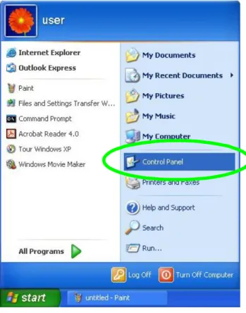
18. Select Start > Control Panel > Network and Internet> Network and Sharing Center >Change Adapter Settings
19. Click on Local Area Connection and choose Properties. You will now see the following screen.
20. Select Internet Protocol (TCP/IP) for your network card.
14 22. Enable DHCP or Static IP:
15
CHAPTER4 ACCESSING THE GATEWAY
For Windows XP/2000 users, your computer should have obtained an IP address after configuring the network settings on your computer. Now you need to configure your The ZyXEL VFG6005 Series VPN Firewall Gateway.
4.1
START-UP AND LOG-IN
Open your WEB browser. In the address box, enter [90HHTTP://192.168.10.1]
When you successfully connect to the configuration interface for the ZyXEL VFG6005 Series VPN Firewall Gateway, the login screen will pop up. Enter your username as [admin] and your password as [1234]. You will now see the Router>Status page of The ZyXEL VFG6005 Series VPN Firewall Gateway. For initial Router Setup, please consult the Quick Start Guide.
16
CHAPTER5 BASIC SETTINGS
5.1
WAN SETUP
17 24. WAN Settings:
The ZyXEL VFG6005 Series VPN Firewall Gateway supports Ethernet WAN and Mobile WAN. Ethernet WAN has three connection types: DHCP, Static and PPPoE. Please ensure which connection type should be used, and select your internet connection type from the pull-down menu.
Whatever WAN connection type you have chosen, The ZyXEL VFG6005 Series VPN Firewall Gateway will get a WAN IP and this IP will be shown in the Router/Status page as below.
18
5.1.1
DHCP (automatic IP address assignment)
The IP address is automatically assigned to you by your ISP. You will see the following screen when you choose DHCP.
WAN Select Enable/Disable to enable/disable WAN Connection Type DHCP
Host Name Some ISP and DHCP servers ask for the Host Name of the DHCP client before assigning an IP address. In this case, please key in your Host Name.
MTU Maximum Transmission Unit
5.1.2
Static (Fixed IP address assignment)
The IP address, subnet mask, gateway, and DNS server are provided by your ISP.
Please enter the information accordingly.
WAN Select Enable / Disable to enable/disable WAN. Connection Type Static IP
External IP Address The external IP addresses offered by the ISP. Netmask The netmask offered by the ISP.
Gateway The gateway offered by the ISP. Static DNS 1 The static DNS 1 offered by the ISP.
19 Static DNS 2 The static DNS 2 offered by the ISP.
MTU Maximum Transmission Unit
5.1.3
PPPoE (connected by username/password)
If your ISP provides the username and password, please enter the information accordingly.
WAN Select Enable/Disable to enable/disable WAN Connection Type PPPoE
Authentication The authentication type CHAP or PAP offered by your ISP. User Name The user name offered by the ISP.
Password The password offered by the ISP.
PPP Connection Type Always Connected will maintain the PPPoE dial up connection. On Demand will connect only when there is traffic.
Max Idle Time
PPPoE On Demand will only be activated when there is traffic. When there is no traffic within the max idle time (default: 300 seconds), the PPPoE connection will be disconnected.
PPP Echo Interval PPPoE echo will ensure whether the link is still up or not (default interval 20 seconds)
PPP Retry Threshold When PPPoE echo retry exceeds PPPoE Retry Threshold (default 20 times), the dial up connection would be recognized as down.
PPP MTU PPPoE maximum transmission unit: up to 1492 bytes (PPPoE‘s header is 8 bytes)(This value should be less than MTU value at least 8 bytes ).
MTU Physical Device Maximum Transmission Unit
Provided by your ISP
20
5.1.4
Ethernet WAN MAC Address Clone
Some ISPs only allow a registered MAC address to access to the internet. To bypass the rule, you need to set up a cloned MAC address for The ZyXEL VFG6005 Series VPN Firewall Gateway using the pre-registered MAC address.
1. Click on [Setup] – [MAC Address Clone] tab. You will see the following screen.
2. Configure your MAC Clone for Ethernet WAN, Mobile WAN and LAN following the instructions below.
Clone WAN MAC If your ISP only grants access to a fixed MAC address, please select Enable. If your ISP does not enforce access control, please select Disable.
MAC Address
If the PC you use to configure The ZyXEL VFG6005 Series VPN Firewall Gateway is the device which has the right MAC address to access the internet, press ―Get My MAC‖ button. You can also type in the MAC Address which has been granted access by your ISP.
5.1.5
Mobile WAN (connected by information related to what your ISP needs)
Please enable and enter the APN, PIN code, user name, and password provided by your ISP. You may also choose from the list of profiles for well known ISP settings. (Please note that some information might not be needed.)
22 WAN Select Enable/Disable to enable/disable WAN
Connection Type Mobile WAN
Modem Brand Select the modem brand you use. You can keep it as Auto for automatic detection. Modem Model Select the modem model you use. You can keep it as Auto for automatic detection.
APN Type Select By Service Provider for specifying the ISP you use, or otherwise choose Custom to assign desired APN.
Service Provider Select your service provider so the Access Point Name (APN) and the Dial Number will be automatically assigned.
Access Point Name (APN) Enter APN string offered by the ISP if you select Custom for APN Type (keep it empty if your ISP doesn‘t need it).
Personal Identification
Number (PIN) Enter PIN code offered by the ISP (keep it empty if your ISP doesn‘t need it). Authentication Choose the authentication method CHAP, PAP or None.
User Name The user name offered by the ISP (keep it empty if your ISP doesn‘t need it). Password The password offered by the ISP (keep it empty if your ISP doesn‘t need it). Dial Number Enter Dial Number offered by the ISP.
Connection Mode Sets the desired connection mode and speed (HSDPA, UMTS, EDGE, GPRS). PPP Connection Type PPPoE Keep Alive will maintain the PPPoE dial up connection.
Max Idle Time Set the max idle time before the mobile WAN is disconnected. (default interval 300 seconds)
PPP Echo Interval PPPoE echo will ensure whether the link is still up or not (default interval 20 seconds)
PPP Retry Threshold When PPPoE echo retry exceeds PPPoE Retry Threshold (default 20 times), the dial up connection would be recognized as down.
23
5.1.6
HSPA+ Super Speed
If you using HSPA+ super speed modem, please choose this WAN connection type. Please enable and enter the APN, PIN code, user name, and password provided by your ISP. You may also choose from the list of profiles for well known ISP settings. (Please note that some information might not be needed.)
24 WAN Select Enable/Disable to enable/disable WAN
Connection Type HSPA+ Super Speed
Modem Brand Select the modem brand you use. You can keep it as Auto for automatic detection.
Modem Model Select the modem model you use. You can keep it as Auto for automatic detection.
APN Type Select By Service Provider for specifying the ISP you use, or otherwise choose Custom to assign desired APN.
Service Provider Select your service provider and the Access Point Name (APN) will be automatically assigned.
Access Point Name (APN) Select By Service Provider for specifying the ISP you use, or otherwise choose Custom to assign desired APN.
Personal Identification Number
(PIN) Please enter PIN code
Connection Mode Select your connection mode. (AUTO mode recommended) WAN MTU Maximum transmission unit
Bigpond Login If you are using ―Bigpond‖ system, please enable this item Bigpond Login Server Please choose the Bigpond server.
Bigpond Login User Name Please enter your User Name provided by Bigpond Bigpond Login Password Please enter your Password provided by Bigpond
TurboLink Enable ―TurboLink‖ to improve the connection speed and stability. (Please note that TurboLink function might increase your 3G data charge)
25
5.2
WAN DETECT
3. Click on [Setup] – [WAN Failover] tab. You will see the following screen.
4. Configure the basic settings of WAN Failover following the instructions below.
Detection Interval This is the interval which specifies how often the VFG6005 series will check the Ethernet WAN connection.
Connection Detection Threshold
The system will generate a PING packet to detect whether the Ethernet WAN connection is still connected. If the Host has not responded for this threshold value, the system is considered to be Ethernet WAN link down.
Detection Timeout This is the timeout time before the connection ping is considered lost. External Connection
Detection
Select Enable/Disable to enable/disable connection detection. This is required for failover from Ethernet WAN to Mobile WAN.
Detection Type Select Gateway or use your own custom Host IP. The VFG6005 series will check the connection to this IP periodically. If at any time the connection ping is lost for the threshold set, the VFG6005 series will switch WAN traffic from Ethernet WAN to Mobile WAN if available.
Custom Detection Host Enter the IP address or domain name of the host to be detected.
Fallback Enable this if you wish for the Mobile WAN connection to fall back to Ethernet WAN when it is available.
26
5.3
LAN SETUP
1. Click on [Setup] – [LAN] tab. You will see the following screen.
2. Configure your LAN following the instructions listed below.
Internal IP Address Please key in Internal IP Address Netmask Select Netmask from the selection list.
Spanning Tree Protocol (STP)
Click Enable only if you will deploy your network in a ring topology. Other switches in the LAN must also support STP. (A cyclic topology will cause network breakdown with STP enabled.)
27
5.4
DHCP SERVER SETUP
The ZyXEL VFG6005 Series VPN Firewall Gateway provides DHCP server service in order to offer IP addresses to the computers within a LAN.
1. Click on [Setup] – [DHCP Server] tab. You will see the following screen.
2. Configure your LAN following the instructions listed below.
DHCP Service Select Enable/Disable to enable/disable DHCP Server. DHCP Starting IP
Address The DHCP starting IP addresses offered by the DHCP Server.
Max DHCP Clients The maximum number of the IP addresses supported by the DHCP server
Lease Please choose lease time from the selection list. You can choose 1 Hour, 3 Hours, 6 Hours, 1 Day, 3 Days, or 7 Days.
Domain Please enter the domain name.
DHCP DNS Server Type
Select OpenDNS Server if you have an OpenDNS account for content filtering. Otherwise choose ISP DNS Server to use your ISP‘s default server or Custom to enter your own IP address.
DHCP DNS Server
28
5.5
DDNS SETUP
DDNS (Dynamic Domain Name Service) allows an ―internet domain name‖ to be assigned to a computer/router which has a dynamic IP address. This makes it possible for other internet devices to connect to the computer/router without needing to trace the changing IP addresses themselves. To enable DDNS, you will first need to sign up for DDNS services from DynDNS.org, TZO.com or ZoneEdit.com.
DDNS is useful when combined with the virtual server feature. It allows other internet users to connect to your virtual server by using a domain name, rather than an IP address. The DDNS service helps users to locate the right IP address by the domain name.
For example, you wish to set up a personal web server. However, you obtain a different IP address from your ISP every time you connect to the internet. The dynamic IP address you have will cause difficulty for other internet users to find your web server. In this case, you will need to enable DDNS, so other users can connect to you through a fixed domain name to disregard the potential varying IP addresses behind the server.
1. Register with one of the DDNS providers (DynDNS.org, TZO.com or ZoneEdit.com) before you configure DDNS on the ZyXEL VFG6005 Series VPN Firewall Gateway.
29 3. Configure your DDNS following the instructions listed below.
DDNS Service Select Enable to enable DDNS service. Select Disable to disable DDNS service.
DDNS Type Select the desired DDNS service provider from the list. User Name Enter your username
Password Enter your password
Host Name Apply for a domain name, and make sure it is allocated to you Action Press Update button to immediately update DDNS information.
30
CHAPTER6 WIRELESS SETTINGS
6.1
BASIC SETUP
Multiple SSIDs allow the ability for separate security mode and key settings to be set by users for both convenience and increased protection. Users are able to configure their network devices to access the first SSID with the WPA2 PSK (Pre-Shared Key) and secret key, whilst share the second SSID with WEP and the periodically changed key for visitors. In addition, users are able to isolate these SSIDs to avoid malicious attacks and prevent certain access for visitors using the second SSID. This then provides users an extremely convenient approach to share the wireless access, provide access internet access for visitors, while possessing a strong security protection system at all times.
6.1.1
Settings
1. Click on [Wireless] – [Basic] tab. You will see the following screen.
2. Configure wireless settings following the instructions below.
Wireless Connection
Select Enable if you would like to turn on the wireless signal Select Disable if you would like to turn off the wireless signal. Wireless Mode Select the wireless mode for 802.11b/g/n or mixed use. Transmission
Power Select the transmission power class from 10%, 25%, 50%, 75%, and 100%. Wireless Channel Select which channel to be located to.
Wireless Isolation Between SSIDs
Select Enable if you would like to block traffic from one SSID to another. Select Disable if you would like to allow traffic from one SSID to another.
31
6.1.2
SSID Settings
Users are able to configure each SSID with its own attributes. Further, various security modes are available based on the user‘s needs and preference: Disable, WEP, WPA Pre-Shared Key, WPA, WPA2 Pre-Shared Key, and WPA2. However, it is important to note that all devices under the wireless network must use the same security mode.
You can configure the security settings of your wireless network to suit your desired preference. Different methods will grant different levels of security. Using encryption - data packet is encrypted before transmission - can prevent data packets from being intruded on by un-trusted parties. However, please note that the higher the security level is, the lower the data throughput becomes.
1. Click on [Wireless] – [Basic] tab. You will see the following screen.
2. Configure SSID settings following the instructions below.
Wireless SSID Select Enable if you would like to turn on this SSID. Select Disable if you would like to turn off this SSID. Wireless SSID
Name Enter the wireless station name you would like to have.
Wireless SSID Broadcasting
The ZyXEL VFG6005 Series VPN Firewall Gateway broadcasts SSID periodically. Select Enable to turn it on or Disable to turn it off.
Enabling SSID Broadcasting brings convenience for users to find and connect The ZyXEL VFG6005 Series VPN Firewall Gateway.
Disabling SSID broadcasting enhances the security by hiding SSID information. Wi-Fi Multimedia
(WMM)
Select Enable to prioritize different traffic types based on their characteristics. For example, VoIP or video traffic will have higher priorities over ordinary traffic.
32 Wireless Isolation
Select Enable if you would like to block traffic between other network devices connecting to this SSID. (recommended)
Select Disable if you would like to allow traffic between other network devices connecting to this SSID.
Security Mode Select WEP/WPA-PSK/WPA/WPA2-PSK/WPA2 for security mode. (WPA2-PSK recommended)
6.1.3
WEP
If WEP is selected, WEP index and keys should be set manually.
WEP Key Index WEP Key Index indicates which WEP key is used for data encryption.
WEP Key (1~4) 64-bit WEP: type 10 hexadecimal digits or 5 ASCII characters 128-bit WEP: type 26 hexadecimal digits or 13 ASCII characters.
33
6.1.4
WPA Pre-shared Key / WPA2 Pre-shared Key
If WPA Pre-shared Key or WPA2 Pre-shared Key is selected, a Pre-shared Key is supposed to be set.
Key Enter the Pre-Shared Key here. This key will be required for wireless users to connect to the SSID.
34
6.1.5
WPA / WPA2
If WPA or WPA2 is selected, the radius server information should be set accordingly.
Radius Server IP Address Enter the RADIUS server‘s IP address.
Radius Server Port Enter the RADIUS server‘s port number. The default port is 1812. Radius Key Enter the RADIUS server‘s IP Address.
Encryption Method Select TKIP, AES or Mixed (TKIP+AES). (AES recommended)
Rekey Method
Select Disable/Time/Packet Number. Rekey by Time/Packet Number will require the user to re-authenticate with the RADIUS server after X Time/Packet Number, may increase overhead.
Rekey Time Interval Enter Rekey Time Interval. Rekey Packet Interval Enter Rekey Packet Number.
Pre-Authentication
Select Enable/Disable for Pre-authentication. If enabled, this allows a wireless user to pre-authenticate with the AP before switching from another AP for quicker roaming.
35
6.2
ADVANCED SETUP
36 4. Configure wireless advanced settings following the instructions below.
Fragmentation Enter the fragmentation bytes. The default value is 2346 bytes. RTS Enter the RTS seconds. The default value is 2347 seconds. DTim Enter the DTim seconds. The default value is 1.
Beacon Interval Enter the interval to send a beacon. The default value is 100 milliseconds. Header Preamble Select Long or Short header preamble.
TxMode Select different transmission mode.
MPDU MPDU data length. The transmission rate is increase when you choose a larger number, but usually the max value will be 4 in the wireless card
MSDU Aggregate A kind of packet aggregation method, it can improve the transmission efficiency. Please make sure you Wireless card has this function supported.
Tx Burst Some 802.11g wireless card can supported this mode, and the transmission rate can be increased when enable this function.
Packet Aggregate An aggregation method like A-MSDU, it can improve the transmission efficiency. Please make sure you Wireless card has this function supported.
HT Control Field Select Enable/Disable. It is useful when you need to debug the wireless network Reverse Direction Grant Select Enable/Disable. The response time can be shorter when enable this
function.
Link Adapt Select Enable/Disable. The function is use to dynamically change the modulation and encode mechanism between wireless devices.
Short Guard Interval (SGI) Select Enable/Disable. Short GI can improve some transmission rate, but with less immunity when interference exist.
Operation Mode Select Mixed mode or Greenfield. You may choose Greenfield mode to increase the transmission rate when you using 802.11n wireless network only.
HT Band Width Using HT20MHz or HT20/40MHz Block Ack Setup
Automatically
Select Enable/Disable. If your Wifi Card supported Block Ack mechanism, it can improve the data transmission efficiency when enable this function.
Block Ack Window Size Specify a Block Ack window size
Reject Block Ack Select Enable to reject the request of BA from other Wireless device MCS Select transmission (connection) speed.
37
6.3
WPS – WIFI PROTECTED SETUP
1. Click on [Wireless] – [WPS] tab. You will see the following screen.
To connect a computer using WPS, click Push Button. Then you will have two minutes to go to your computer, select the wireless network and connect. If your computer asks for a WPS PIN Code, that can be generated by clicking the Generate PIN Code button. If you are connecting to a device that has a WPS button, first click the WPS Push Button and then press the WPS button on that device within 2 minutes. This will connect the two devices together.
WPS Enable Select Enable or Disable to activate or deactivate WPS.
WPS Router PIN Code Click ―Generate PIN Code‖ to automatically generate a random WPS PIN code. WPS Push Button Click this button to start the WPS process.
38
CHAPTER7 SECURITY SETTINGS
7.1
FIREWALL SETUP
1. Click on [Security] – [Firewall] tab. You will see the following screen.
2. Configure Security Settings following the instructions below.
SPI Firewall Protection Select Enable to enable SPI Firewall Protection. Select Disable to disable SPI Firewall Protection. TCP SYN DoS
Protection
Check to enable TCP SYN DoS Protection. Uncheck to disable TCP SYN DoS Protection.
TCP SYN DoS attack sends a flood of TCP/SYN packets. Each of these packets are like a connection request, causing the server to consume computing
resources (e.g. memory, CPU) to reply and to continuously wait for the incoming packets. Without TCP SYN Dos Protection, the resources in the server will be easily consumed completely. This will then consequently result in the dysfunction of the server.
The ZyXEL VFG6005 Series VPN Firewall Gateway is able to detect TCP SYN DoS attacks and limits the resource consumption by lowering the incoming request rate by fast recycling the resource. Therefore, the ZyXEL VFG6005 Series VPN Firewall Gateway is still able to serve normal traffic while it is under such an attack.
ICMP Broadcasting Protection
Check to enable ICMP Broadcasting Protection. Uncheck to disable ICMP Broadcasting Protection.
ICMP broadcasting attack is a type of DoS attacks. A flood of ICMP broadcasting packets is generated and sent to a server (like the ZyXEL VFG6005 Series VPN
39 Firewall Gateway). Consequently, this server will suffer from a huge amount of
interruptions and consumption of computing resources.
The ZyXEL VFG6005 Series VPN Firewall Gateway is able to stop responding to ICMP broadcasting echo packets in order to avoid a potential ICMP broadcasting DoS attack.
ICMP Redirect Protection
Check to enable ICMP Redirect Protection. Uncheck to disable ICMP Redirect Protection.
An ICMP redirect message is a way to change the existing routing path. Generally, ICMP redirect packets should not be sent, and so when there is the occurrence that ICMP redirect packets are sent, it is important to note that it is very likely to be used as a means for a network attack.
40
7.2
ACCESS CONTROL LIST (ACL) SETUP
7.2.1
ACL Settings
1. Click on [Security] – [Access Control] tab. You will see the following screen.
Please do not change the parameters unless you wish to customize it by yourself.
2. Configure Access Control List (ACL) Settings following the instructions below.
ACL Select Enable to enable ACL. Select Disable to disable ACL. Default ACL
Action
Check Enable to enable a specific MAC Filter rule. Uncheck Enable to disable a specific MAC Filter rule.
Type the MAC address to permit a device to access to the network.
* Enabling MAC filtering blocks all MAC addresses which are not listed in the MAC Filter Rule. Be aware that adding the MAC address of your managing computer is required in order to access to the ZyXEL VFG6005 Series VPN Firewall Gateway.
41 3. Click on [Add] tab. You will see the following screen.
4. Configure [Add Access Control List (ACL)] Settings following the instructions below
Sequence Number This defines the sequence of the ACL rules. If a packet fits the conditions set by the ACL rules, the packet will then be sorted according to the first ACL rule from the top of the list.
Rule Name Name of the ACL rule. Rule Enable Enable/Disable this ACL rule
External Interface Please select which External Interface (WAN1 or WAN2) you want a packet to go through, IF the packet fits the condition of this ACL rule.
Internal IP Range Set up the internal IP range for this ACL rule. External IP Range Set up the external IP range for this ACL rule.
Protocol Set up the protocol (TCP or UDP) for the ACL to be enabled.
Service Port Range Set up the Service Port Range (e.g., HTTP is TCP/80) for the ACL to be enabled.
42 5. Example: Filter and block MSN usage.
For example, a company does not wish to allow employees to use MSN. The system administrator can set up an ACL action: rejecting the traffic going out to External IP Range at 207.46.110.*/24.
Rule Name MSN Blocking Rule Enable Enable
External Interface * (All complies)
Internal IP Range Keep it blank (All complies)
External IP Range 207.46.110.1:207.46.110.1.254 (IP address range for MSN server)
Protocol TCP
Service Port Range Keep it blank (All complies)
43
7.3
MAC ACCESS CONTROL SETUP
1. Click on [Security] – [MAC Access Control] tab. You will see the following screen.
2. Configure ACL Settings following the instructions below.
MAC Access Control Choose Enable/Disable to enable/disable MAC access Control Default MAC Access Control
Action
The default ACL action of the ACL rules. When you add the individual rules, it can be viewed as exceptions and take effects relating to the default action. If the action of the adding rule is the same as the default action, then this rule will not work.
3. Click on [Add] tab. You will see the following screen.
44 If users need to bind an IP to a specified MAC (network device), one can follow the settings as below.
Sequence Number User1 Rule Name Enable
MAC 00:33:44:55:66:77 Action Allow Access ACL Enable Enable Static ARP Enable Enable Static DHCP
Enable Enable
45
7.4
OpenDNS SETUP
7.4.1
OpenDNS Settings
1. Click on [Security] – [OpenDNS] tab. You will see the following screen.
2. Configure OpenDNS Settings following the instructions below.
OpenDNS Service Choose Enable/Disable to enable/disable OpenDNS OpenDNS Username Enter OpenDNS user name.
OpenDNS Password Enter OpenDNS password.
DNS Query Redirection to OpenDNS DNS Servers
Choose Enable/Disable to enable/disable the data flow redirect to the OpenDNS Server. Users can get advanced content filtering function through the setting
46
7.5
WEB FILTERING SETUP
1. Click on [Security] – [Web Filtering] tab. You will see the following screen.
2. Configure Web Filtering Settings following the instructions below.
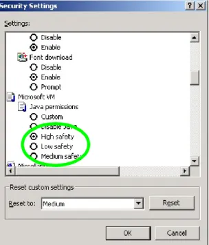
Web Filtering Choose Enable/Disable to enable/disable Web Filtering Activex Filtering Choose Enable/Disable to enable/disable Activex Filtering
Java/JavaScript Filtering Choose Enable/Disable to enable/disable Java/JavaScript Filtering Proxy Filtering Choose Enable/Disable to enable/disable Proxy Filtering
47
7.5.1
Added Web Filtering Rules
1. Click on [Add] tab. You will see the following screen.
2. Configure Web Filtering Settings following the instructions below
Sequence Number This defines the sequence (priority) of all the Web Filtering rules. Rule Enable Choose Enable/Disable to enable/disable Web Filtering rule Filter Keyword Enter the Keyword
Filter Type Choose URL or Sever Action Select ALLOW / DENY。
3. Example: Block a URL with Keyword
48
7.6
VPN / PPTP SETUP
7.6.1
VPN / PPTP Settings
PPTP VPN allows you to create a secure VPN connection remotely to your LAN. PPTP can allow you to connect using built in software clients such as Windows VPN client or smart devices such as Android phones/tablets, iPhones or iPads.
49 2. Configure PPTP Settings following the instructions below.
PPTP Choose Enable/Disable to enable/disable L2TP. MTU Enter MTU value. The default value is 1482 bytes.
VPN Start IP Address Enter the VPN start IP address. The default value is 192.168.39.1. Max VPN Clients Enter the max VPN clients.
Auto DNS Choose Enable/Disable to enable/disable Auto DNS. DNS Enter DNS server if you choose Disable for Auto DNS.
CHAP Enable Choose Enable/Disable to enable/disable CHAP for VPN authentication. MSCHAP Enable Choose Enable/Disable to enable/disable MSCHAP for VPN authentication. MSCHAP2 Enable Choose Enable/Disable to enable/disable MSCHAP2 for VPN authentication. MPP128 Enable Choose Enable/Disable to enable/disable MPP128 encryption.
Proxy ARP Enable Choose Enable/Disable to enable/disable Proxy ARP. NAT Enable Choose Enable/Disable to enable/disable NAT.
50
7.6.2
Add VPN / PPTP Rule
1. Click on [Add] tab. You will see the following screen.
2. Configure [Add PPTP] Settings following the instructions below.
Sequence Number This defines the sequence of the PPTP rules. Rule Enable Enable/Disable this PPTP rule
User Name Enter PPTP user name. Password Enter PPTP password.
51
7.7
VPN / L2TP SETUP
7.7.1
VPN / L2TP Settings
L2TP allows you to create an insecure VPN connection to your LAN. Because L2TP is insecure, we suggest that you use PPTP or L2TP over IPSec. Also both L2TP and L2TP over IPSec have the restriction that the VPN client cannot be behind a NAT router and must have a routable public IP address.
52 2. Configure PPTP Settings following the instructions below.
L2TP Choose Enable/Disable to enable/disable L2TP. MTU Enter MTU value. The default value is 1482 bytes.
VPN Start IP Address Enter the VPN start IP address. The default value is 192.168.39.1. Max VPN Clients Enter the max VPN clients.
Auto DNS Choose Enable/Disable to enable/disable Auto DNS. DNS Enter DNS server if you choose Disable for Auto DNS.
CHAP Enable Choose Enable/Disable to enable/disable CHAP for VPN authentication. Proxy ARP Enable Choose Enable/Disable to enable/disable Proxy ARP.
NAT Enable Choose Enable/Disable to enable/disable NAT.
7.7.2
Add VPN / L2TP Rule
3. Click on [Add] tab. You will see the following screen.
4. Configure [Add PPTP] Settings following the instructions below.
Sequence Number This defines the sequence of the PPTP rules. Rule Enable Enable/Disable this PPTP rule
User Name Enter PPTP user name. Password Enter PPTP password.
53
7.8
VPN / IPsec SETUP
7.8.1
VPN / IPsec Settings
1. Click on [Security] – [VPN / IPsec] tab. You will see the following screen.
2. Configure IPsec Settings following the instructions below.
54
7.8.2
Add VPN / IPsec Rule
55 2. Configure [Add - IPsec] Settings following the instructions below.
Sequence Number This defines the sequence of the IPsec rules. Connection Name Name of the IPsec rule.
Rule Enable Enable/Disable this IPsec rule VPN Mode Net-to-Net or Road Warrior
Local External Interface Select the external WAN for the local VPN gateway. Local Internal IP Address Select the subnet IP address for the VPN gateway.
Local Netmask Select the netmask for the local VPN gateway.
Remote Gateway Enter the IP address or domain name of the remote VPN gateway. This option is needed in Net-to-Net mode.
Remote Subnet IP Enter the subnet IP address of the remote VPN gateway. This option is needed in Net-to-Net mode.
Remote Netmask Enter the subnet netmask of the remote VPN gateway. This option is needed in Net-to-Net mode.
Connection Initiation Check the local VPN gateway to initiate the connection. This option is needed in Net-to-Net mode.
IKE Key Mode PSK.
Preshared Key Enter the preshared key. The key should be at least 8-digit ASCII string. L2TP Enable Check the local VPN gateway to enable L2TP. This option is needed in Road
Warrior mode.
Advanced Options Check it if you need to configure the advanced options. Phase 1 Mode Main.
Phase 1 ID Enter the phase 1 ID.
Phase 1 Lifetime Enter the phase 1 lifetime. This value is between 3600 and 28800 seconds. Phase 2 Lifetime Enter the phase 2 lifetime. This value is between 3600 and 28800 seconds. Phase 1 Authentication Select the phase 1 authentication as MD5 or SHA1. (SHA1 recommended) Phase I Encryption Select the phase 1 encryption as DES, 3DES or AES. (AES recommended) Phase 1 Group Key
Management
Select the phase 1 group key management as DH1, DH2 or DH5.
Phase 2 Authentication Select the phase 2 authentication as MD5 or SHA1. (SHA1 recommended) Phase 2 Encryption Select the phase 2 encryption as DES, 3DES or AES. (AES recommended) Phase 2 Group Key
Management
56
CHAPTER8 APPLICATIONS SETTINGS
8.1
PORT RANGE FORWARD SETUP
By activating the port range forwarding function, remote users can access the local network via the public IP address. Users can assign a specific external port range to a local server. Furthermore, users can specify an internal port range associated in a port range forwarding rule. When the ZyXEL VFG6005 Series VPN Firewall Gateway receives an external request to access any one of the configured external ports, it will redirect the request to the corresponding internal server and change its destination port to one of the internal ports specified. Therefore, if users do not wish for destination port to be changed for a request, the internal port range should be left empty.
Certain applications in a LAN are available only after activating the port range forwarding, including servers and online gaming. When an Internet request wants to access a port, the ZyXEL VFG6005 Series VPN Firewall Gateway will dispatch it to the IP specified. Due to security reasons, users are suggested to limit the use of port range forwarding, and cancel it when the application is not used.
By enabling DMZ Host Function, you can set up a DMZ host at a particular computer exposed to the Internet. In this way, some applications, especially online games (if the traffic port numbers of the applications are always changing), can be easily accessed.
57
8.1.1
Port Range Forward Settings
1. Click on [Applications] – [Port Range Forward] tab. You will see the following screen.
2. Configure [DMZ] Settings following the instructions below
DMZ Select Enable to enable DMZ function. Select Disable to disable DMZ function.
DMZ IP Address Enter the IP address of a particular host in your LAN which will receive all the packets originally going to the WAN port / Public IP address above.
58 3. Configure [Port Range Forwarding] Settings following the instructions below
Port Forwarding Select Enable / Disable to enable/disable Port Forwarding
8.1.2
Add Port Range Forwarding Rule
1. Click on [Add] tab. You will see the following screen.
2. Configure [Add Port Range Forwarding Rule] Settings following the instructions below
Sequence Number
This defines the sequences (priorities) of the port forwarding rules. If a packet fits the conditions setup by the port forwarding rules, the packet will then be
forwarded according to the 1st rule from the top of the list. Rule Name Enter the name of the port forwarding rule.
Rule Enable Check/Uncheck to enable/disable this port forwarding rule. External Interface Choose WAN1 or WAN2 as the External port forwarding interface. Protocol Choose TCP, UDP or TCP/UDP for the rule to be applied.
External Port Range Set up the External Port Range for the rule to be applied. Internal IP Set up the Internal IP for the rule to be applied.
59
8.2
1-1 NAT
1-1 NAT allows you to map an external Public IP address to an internal LAN IP address. If you have
a range of Public IP addresses assigned by your ISP, you can use each of those IP addresses to
assign to a specific LAN server. For example, you can assign a Public IP address to a Web Server or a
Mail Server that needs to be accessed publicly through the Internet.
8.2.1
1-1 NAT Settings
1. Click on [Applications] – [Virtual Hosts] tab. You will see the following screen.
8.2.2
Add 1-1 NAT Rule
1. Click on [Add] tab. You will see the following screen.
2. Configure [Add Port Range Forwarding Rule] Settings following the instructions below
Sequence Number
This defines the sequences (priorities) of the port forwarding rules. If a packet fits the conditions setup by the port forwarding rules, the packet will then be forwarded according to the 1st rule from the top of the list.
Rule Name Enter the name of the virtual hosts rule.
60 External Interface Choose Ethernet WAN or Mobile WAN as the External virtual host interface.
External IP Address Enter the External IP Address.
Mapped LAN IP Address Enter the Mapped LAN IP Address this External IP Address will be mapped to.
61
8.3
STREAMING/VPN PASS-THROUGH
You can enhance your media streaming quality by enabling RTSP, MSS, and H.323 protocols. Moreover, VPN Pass-through functionality can also be enabled.
1. Click on [Applications] – [Streaming / VPN] tab. You will see the following screen.
2. Configure [Streaming] Settings following the instructions below.
RTSP Select Enable/Disable to enable/disable RTSP MMS Select Enable/Disable to enable/disable MMS 3. Configure [Video Conference] Settings following the instructions below
H.323 Select Enable/Disable to enable/disable H.323 4. Configure [VPN] Settings following the instructions below
IPSec Pass-through Select Enable/Disable to enable/disable IPSec Pass-through PPTP Pass-through Select Enable/Disable to enable/disable PPTP Pass-through
62
8.4
UPnP/NAT-PMP SETUP
1. Click on [Applications] – [UPnP / NAT-PMP] tab. You will see the following screen.
2. Configure [UPnP] Settings following the instructions below
UPnP Select Enable/Disable to enable/disable UPnP NAT-PMP Select Enable/Disable to enable/disable NAT-PMP UPnP Port Enter the number for UPnP port.
63
CHAPTER9 DYNAMIC BANDWIDTH MANAGEMENT
9.1
DBM SETUP
Bandwidth Management provides two powerful and unique mechanisms to manage bandwidth: Static Bandwidth Management (SBM) and Dynamic Bandwidth Management (DBM). SBM provides users with the option to allocate a fixed amount of bandwidth for a specific computer or a particular application, while DBM intellectually manages the rest of the bandwidth while all the time satisfying the complicated bandwidth requirements/settings of SBM.
DBM automatically and consistently monitors bandwidth usage, prioritizes traffic, and allocates bandwidth to all users and applications. Real-time applications such as VoIP, online gaming, and video conferencing, are granted a higher priority for bandwidth usage. On the other hand, applications such as P2P and FTP are given a lower priority. However, when P2P software is the only application running on the network, DBM is able to provide an efficient allocation and ensure that no bandwidth is wasted by being able to recognize that it is the only application running. Once real-time applications join the network, these applications will then immediately have a higher priority to use bandwidth than P2P software. Therefore, users can play online games, stream network videos, listen to network radio, chat with friends, send e-mails, and run P2P applications, all at the same time with no disturbances!
9.1.1
DBM Settings
The essential configuration needed by Bandwidth Management is to specify accurately the bandwidth you have. Bandwidth Management would then dispatch bandwidth according to this information. Please Note: Improper bandwidth assignment may cause Bandwidth Management to work ineffectively.
64 1. Click on [Bandwidth] – [Bandwidth Management] tab. You will see the following screen.
2. Bandwidth Settings:
Please adjust your bandwidth type according to your bandwidth (download/upload) subscribed from your ISP. Due to the unstable nature of network bandwidth supported by ISP, users are recommended to reserve a portion of bandwidth for buffering usage, and Bandwidth Management would then arrange the reserved bandwidth under heavy traffic.
Bandwidth Type (Download/Upload)
Select the correct bandwidth type according to your Internet service subscription.
If the bandwidth type is not available on the list, select Custom. Download Bandwidth Enter the value to customize download bandwidth.
Upload Bandwidth Enter the value to customize upload bandwidth. Reserved Buffering
Bandwidth Enter the value to provide bandwidth buffer.
3. Advanced Setting Example
A user subscribed 10M/2Mbps bandwidth from ISP. After performing some speed test, the user found that the actual bandwidth is about 1135KByte/sec downloading and 200KByte/s uploading. We change the dimension in Kbps as follows,
65 Upload Speed: 200KB/s x 8 = 1600Kbp/s
The settings can be done as below,
Bandwidth Type
(Download/Upload) Select custom。
Download Bandwidth Enter the value to 9080。 Upload Bandwidth Enter the value to 1600。 Reserved Buffering
Bandwidth
User can firstly set the value about 10% and adjust this value later. If your network is very stable, you could lower this value.
9.1.2
Add SBM Rules
1. Click on [Add] tab. You will see the following screen.
2. Configure [Add SBM] Settings following the instructions below.
Sequence Number This defines the sequence of the SBM rules. If a packet fits the conditions set by the SBM rules, the packet will then be sorted according to the first SBM rule from the top of the list.
Rule Name Name of the SBM rule. Rule Enable Enable/Disable this SBM rule
Internal IP Set up the internal IP for this SBM rule.
66 External Interface Please select which External Interface (WAN1 or WAN2) you want a packet to
go through, IF the packet fits the condition of this SBM rule.
Service Port Range Set up the Service Port Range (e.g., HTTP is TCP/80) for the SBM to be enabled.
Bandwidth Allocation By Ratio or By Bandwidth
Ratio The ratio of the whole bandwidth according to the External Interface. Download Enter the reserved download bandwidth.
Upload Enter the reserved upload bandwidth. Utilize Bandwidth More
than Guaranteed
Check this box if you wish to allow the traffic confirming this SBM rule to be able to utilize the whole bandwidth when the bandwidth is idle.
3. Advanced Setting Example1
If a user needs to reverse some bandwidth for a specified application, such as VoIP, one can have the following configuration to reserve a 25Kbps/25Kbps bandwidth for VoIP application.
Rule Name VoIP
Rule Enable Check the box to enable this rule
Internal IP Address Enter the IP address of the VoIP machine
Protocol Select * will apply this rule for both TCP and UDP protocols External Interface Choose the WAN interface you want to use
Service Port Range Enter the service port number that used by VoIP
67 4. Advanced Setting Example 2
In the case users need to guarantee a PC or a network device for a specified bandwidth and allow the user to user rest bandwidth up to some values, one may follow the settings as below.
In this case, the PC with IP address-192.168.10.100 will be guaranteed for 100Kbps/20Kbps bandwidth. Additionally, this PC can use up to 150Kbps/30Kbps if there is still any free bandwidth existed.
Download Enter the reserved download rate to 25 Kbps Upload Enter the reserved upload rate to 25 Kbps
Utilize Bandwidth More Than Guaranteed
Uncheck this box to reserve a fixed rate for this application; You may also check this box allowing this application use any free available bandwidth when it consumes more bandwidth.
Rule Name IP1_Rate
Rule Enable Check this box to enable this rule
Internal IP Address Enter the IP address this rule to be applied to. Protocol * (Applied to both TCP and UDP)
External Interface Select the external WAN Interface to be applied to. Service Port Range Applied to all port range if left this field blank
Bandwidth Allocation Allocating the bandwidth by fixed value assignment or ratio Download Enter the download guaranteed value to 100 Kbps。 Upload Enter the upload guaranteed value to 25 Kbps。