V T T S Y M P O S I U M
RATU2
The Finnish Research Programme
on the Structural Integrity
of Nuclear Power Plants
Synthesis of achievements 1995–1998
VTT SYMPOSIUM 190
Keywords: nuclear power plants, nuclear reactor safety, structural integrity, research programsRATU2
The Finnish Research Programme
on the Structural Integrity
of Nuclear Power Plants
Synthesis of achievements
1995
−
1998
Espoo, 7 December, 1998
Edited by
Jussi Solin, Matti Sarkimo, Merja Asikainen & Åsa Åvall
VTT Manufacturing Technology
Organised by
ISBN 951–38–5263–6 (soft back ed.) ISSN 0357–9387 (soft back ed.)
ISBN 951–38–5264–4 (URL: http://www.inf.vtt.fi/pdf/) ISSN 1455–0873 (URL: http://www.inf.vtt.fi/pdf/)
Copyright © Valtion teknillinen tutkimuskeskus (VTT) 1998 JULKAISIJA – UTGIVARE – PUBLISHER
Valtion teknillinen tutkimuskeskus (VTT), Vuorimiehentie 5, PL 2000, 02044 VTT puh. vaihde (09) 4561, faksi 456 4374
Statens tekniska forskningscentral (VTT), Bergsmansvägen 5, PB 2000, 02044 VTT tel. växel (09) 4561, fax 456 4374
Technical Research Centre of Finland (VTT), Vuorimiehentie 5, P.O.Box 2000, FIN–02044 VTT, Finland phone internat. + 358 9 4561, fax + 358 9 456 4374
VTT Valmistustekniikka, Voimalaitosten materiaalitekniikka, Kemistintie 3, PL 1704, 02044 VTT puh. vaihde (09) 4561, faksi (09) 456 7002
VTT Tillverkningsteknik, Material och strukturell integritet, Kemistvägen 3, PB 1704, 02044 VTT tel. växel (09) 4561, fax (09) 456 7002
VTT Manufacturing Technology, Materials and Structural Integrity, Kemistintie 3, P.O.Box 1704, FIN–02044 VTT, Finland
Phone international + 358 9 4561, Fax + 358 9 456 7002
Preface
This Symposium summarises the scientific and technical achievements within the Finnish research programme on the structural integrity of nuclear power plants (RATU2). The programme began in 1995 and will be accomplished at the end of 1998. The main sources of the programme funding were public, i.e. the Ministry of Trade and Industry (KTM), VTT (Technical Research Centre of Finland) and the Radiation and Nuclear Safety Authority (STUK), but also the power companies Imatran Voima Oy (IVO) and Teollisuuden Voima Oy (TVO) has participated in the funding.
An outline of the programme is given in the first paper of this proceedings. The major scientific and technical results are described in the following technical papers. The main objectives and achievements within the programme are summarised in the last paper of this proceedings.
The presentations for this symposium have been selected by a team of the editors and project leaders Kim Wallin1, Pertti Aaltonen1, Pentti Kauppinen1,
Heli Talja1, Kari Laakso2, Olavi Keski-Rahkonen3. The members of the
programme steering and project reference groups provided valuable efforts and experience for the planning and steering of the research. In addition, we are grateful to all colleagues participating in the research work and preparing of this symposium.
Espoo, November, 1998
Jussi Solin Matti Sarkimo Merja Asikainen Åsa Åvall
1
VTT Manufacturing Technology
2
Contents
PREFACE 3
RATU2 research for safety and operability 7
Jussi Solin
Fracture mechanical materials characterisation 23
Kim Wallin, Tapio Planman and Markku Nevalainen
Fracture analysis of ductile elastic-plastic materials under mixed-mode I-II
loading 45
Anssi Laukkanen
Comparison of transition temperature criteria applied for KLST and
ISO-V type Charpy specimens 77
Tapio Planman, Matti Valo and Kim Wallin
Material deterioration due to neutron irradiation 91
Matti Valo and Kim Wallin
Method development for studies of environmentally assisted
cracking (EAC) 105
Päivi Karjalainen-Roikonen, Pekka Moilanen, Aki Toivonen and Pertti Aaltonen
Modelling of environmentally assisted cracking 125
Pertti Aaltonen, Timo Saario, Hannu Hänninen, Jussi Piippo, Ulla Ehrnstén and Marjo Itäaho
Oxide films in high temperature aqueous environments 145
Timo Laitinen, Kari Mäkelä, Timo Saario and Martin Bojinov
Development of tools and models for computational fracture assessment 177
Heli Talja and Kari Santaoja
Structural analysis of NPP components and structures 195
Verification of analysis methods through participation in
the NESC1 programme 221
Rauno Rintamaa, Tapio Planman, Heikki Keinänen, Heli Talja and Pentti Kauppinen
Non-destructive inservice inspections 237
Pentti Kauppinen, Matti Sarkimo and Kari Lahdenperä
Analysis of maintenance strategies 251
Kari Laakso and Kaisa Simola
Models on reliability of non-destructive testing 263
Kaisa Simola and Urho Pulkkinen
Human and organisational factors in the reliability of
non-destructive testing (NDT) 271
Leena Norros
Fire safety 281
Olavi Keski-Rahkonen, Jouni Björkman, Simo Hostikka, Johan Mangs, Risto Huhtanen, Helge Palmén, Arto Salminen and Antti Turtola
RATU2 research objectives and achievements 309
Jussi Solin and Matti Sarkimo
APPENDIX 1. List of publications 36 p.
RATU2, research for safety and operability
Jussi Solin
VTT Manufacturing Technology Espoo, Finland
1. Introduction
The Finnish research programme on the structural integrity of nuclear power plants, RATU2 was launched in 1995 for four years to coordinate the independent national research and development work aiming for structural safety in NPP’s. The general planning and goal setting of the programme was based on the research need assessment and evaluation of the previous RATU programme. The research plans have been updated and refined annually on the basis of available funding.
The RATU2 programme is briefly introduced in this paper. The role of RATU2 in the national nuclear energy research field, the research areas, administrative data, main objectives and future plans are the topics of this presentation. See the following technical papers for the major scientific and technical results, and the last paper in this symposium for a summary of achievements within the RATU2 programme.
2. Nuclear energy research in Finland
In Finland about one third of the electrical energy is generated by nuclear power. Imatran Voima Oy runs two VVER type pressurized water reactors (PWR) in Loviisa and Teollisuuden Voima Oy runs two boiling water reactors (BWR) in Olkiluoto. Continued safe and economic operation of these plants is possible only when strict safety and reliability requirements are fulfilled.
for research and development, as well as in establishing the framework for international collaboration. This role is supported by focused public research programmes:
• Reactor Safety (RETU), 1995 - 1998,
• Structural Integrity of Nuclear Power Plants (RATU2), 1995 - 1998,
and
• Publicly Administrated Nuclear Waste Management (JYT2001),
1997 - 2001.
Publicly funded research in the fields of programmable automation and environmental impacts is currently carried out in separate projects. Most of the public research is conducted by the Technical Research Centre of Finland (VTT). The universities participate to projects co-ordinated by VTT or have separate projects on specific topics. The power companies take care of the plant-specific issues and of the nuclear waste disposal.
In 1996 the RATU2 programme represented 6% of the nuclear energy R&D in Finland. An overview of the volumes of different research areas and the funding basis of the nuclear energy research in Finland in 1996 is shown in Fig. 1.
3. Main objectives of the RATU2 programme
The structural safety of nuclear power plants is largely dependent on materials and the design of the structures. Research in these areas aims to prevent accidents and unscheduled outages. Consequently, the concerns and risks arising from faults in equipment and structures can be kept to a minimum.After a substantial operation time the ageing of the structures and components in the Finnish nuclear power plants is one of the main issues to be considered when safety and economic operation of the plants is evaluated. At the same time, ways are being sought to extend the lifetime of components.
Nuclear R&D in Finland 1996
Others 5 % Fusion Research
7 % .
Other waste manag. 26 %
43 % Other reactor safety RATU2 programme 6 % RETU programme 8 % 5 % . JYT Programme V T T 7 % K T M 1 0 % S T U K 8 % EU 4 % O th e r s 6 % 6 5 % U tilitie s
Figure 1. Funding of nuclear energy research in Finland in 1996.
The loading capacity of the critical main structures must always, during the operating time of the plant, exceed the loading stresses. One of the main objectives of the RATU2 research programme is to quantitatively evaluate the safety margins by developing and applying expertise in materials research, structural analyses, NDE, reliability and fire safety technology and also by applying various research, testing and analysis capabilities. Whenever feasible,
The RATU2 research programme also plays an important role in the education of new experts, technology transfer and international exchange of scientific results.
The aims and research plans for the RATU2 programme were compiled and published in the start-up phase (VTT, 1994).
4. Realisation of the RATU2 programme
4.1 Financial framework
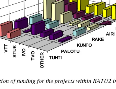
The Finnish research programme on the structural integrity of nuclear power plants, RATU2 was launched in 1995 and it will be completed by the end of 1998. The annual budgets exceeded FIM 10 million, i.e., were round 2 million ECU per annum. This covered about 15 person-years of work for each year. The project on material degradation in the reactor environment (RAVA) alone represents one half of the programme and the project on structural analyses for nuclear power plant components (RAKE) one fifth. The volume distribution between the projects is shown in Fig. 2.
4.2 Funding of the RATU2 programme
A summary of the funding of the RATU2 programme in 1995 - 1998 is shown in Figs. 3 and 4. The funding of the Ministry of Trade and Industry (KTM) has been allocated to the individual projects according to the original plans and suggestions of the steering group. VTT is funding the programme from its internal strategic research resources with the aim of developing most relevant expertise and facilities for this customer sector. The other parties have allocated their funding into specific tasks and thereby provided clear signals for steering of the projects.In addition to the here reported direct funding, the Radiation and Nuclear Safety Authority (STUK) and the Utilities (IVO and TVO) provide also significant work contributions to the RATU2 programme.
COMPONENTS 20 % NDE 12 % FIRE SAFETY 9 % MAINTENANCE 6 % COORDINATION 5 % MATERIALS AND ENVIRONMENT 48 %
Figure 2. Distribution of expenses between the projects in RATU2 programme.
KTM 40 % VTT 30 % STUK 11 % IVO 6 % TVO 6 % OTHERS 7 %
KTM VTT STUK IVO TVO OTHER RAVA AIRI RAKE KUNTO PALOTU TUHTI 0 1 2 3 4 5 6 7 8 Million FIM
Figure 4. Distribution of funding for the projects within RATU2 in 1995 - 1998.
4.3 Organisation
For effective technical management, the RATU2 research programme is divided into five technical and one co-ordination projects as follows:
• Material degradation in the reactor environment (RAVA)
• Reliability of nondestructive inspections of nuclear power plants (AIRI)
• Structural analyses for nuclear power plant components (RAKE)
• Maintenance strategies and reliability (KUNTO)
• Fire safety (PALOTU)
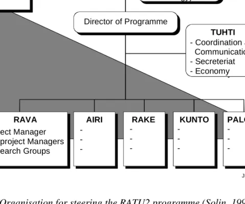
VTT Manufacturing Technology has the general responsibility of the programme, but for the project execution it closely co-operates with VTT Automation, VTT Building Technology, VTT Energy and Helsinki University of Technology. The co-ordination principles are documented in (Solin, 1997). The programme is organised into five research projects, each having specific objectives, but transparent borders. In addition, a separate program is formed for general co-ordination. The programme organisation is illustrated in Fig. 5.
- Coordination and Communication - Secreteriat - Economy Ministry of Trade and Industry Steering Group TUHTI - Coordination and Communication - Secreteriat - Economy
RAVA AIRI RAKE KUNTO PALOTU
- Project Manager - Subproject Managers - Research Groups -Reference Groups Director of Programme Coordinating Unit (VTT Manufacturing Technology) JPSTUHTI
Figure 4. Organisation for steering the RATU2 programme (Solin, 1997).
Representatives of the Ministry of Trade and Industry (KTM), Radiation and Nuclear Safety Authority (STUK), utilities (IVO, TVO), VTT and Helsinki University of Technology form the steering group which is responsible of
4.4 Co-operation
Although each of the research projects has specific objectives and budget, the research work joins the project teams in flexible ways into the task groups. As the practical problems are multidiciplinary, some are dealt with in several projects within the RATU2 programme and/or linked to other international programmes. Perhaps the best example of this kind of cooperative work is the ongoing NESC1 activity:
The experimental verification of integrity assessments for nuclear power plant components requires expensive large scale tests, which could not be performed within the domestic research budgets without participation to the international network NESC. The participation to NESC1 is organised into two projects, AIRI and RAKE, where NDE and structural analysis are considered. However, the fracture mechanical assessment requires the experimental and analytical expertise for materials characterisation being developed in the RAVA project. Furthermore, the reliability modelling in the KUNTO project utilises the results of the nondestructive inspection round robins.
The networks, such as AMES, NESC and PISC, coordinated by the Joint Research Centre (JRC) of the European Union, as well as the Nordic NKS co-operation are considered very important for technology transfer and international exchange of results. The participation to the international CIR program coordinated by EPRI, to the OECD Halden reactor project, to the EURATOM Nuclear Fission Safety (NFS) projects and some other international projects is also organised through the RATU2 programme. This arrangement provides a forum for coordinated domestic funding and steering of these related activities. It also makes possible to use the existing technology transfer channels and reference groups together with the Finnish authorities and utilities.
5. Targetted research areas
5.1 Material degradation in the reactor environment
During the use of nuclear reactors the properties of the structural materials change. Variations in the operation environment, such as changes in water chemistry, may enhance the development and growth of flaws. Neutron radiation embrittles reactor pressure vessel materials. Radiation, together with water chemistry, increases the possibility of stress corrosion cracking in stainless steels and superalloys used in the reactor internal parts. Thermal ageing embrittles cast austenitic stainless steels. Research on structural materials endeavours to study the ageing mechanisms of materials, and the possibilities and methods of preventing or forecasting the damage caused to structures by ageing.
Research carried out on structural materials enables identifying various ageing phenomena and produces essential source data, which is used in estimating the safety of nuclear plants and their remaining operating life. The reliability of structural integrity analyses is directly dependent upon the relevancy and accuracy of material properties used as input for these analyses. Thus, it is imperative that the material properties determined experimentally are reliably transferable to describe the structural detail in question.
The RAVA project had originally four target areas:
• to improve the implementation, reliability and usability of fracture
mechanical material characterization, and to develop new advanced models for the prediction of radiation damage,
• to study the mechanisms of radiation damage and recovery and to
develop a new generation of radiation monitoring programmes, with special emphasis on the situation after thermal annealing,
• to evaluate the factors affecting the changes in material properties due to the environment and stresses and to assess their interrelationship, and
• to establish the applicability of the latest repair technologies and the reliability of the repairs, and to study the benefits of new materials and manufacturing technologies.
A fifth target area was introduced in 1997:
• to identify the correlation between the high temperature water
chemistry, stress corrosion susceptibility and rise of radiation levels through contamination, and to prevent failures and activity rise by monitoring of the water chemistry.
5.2 Reliability of non-destructive inspections of
nuclear power plants
During in-service inspections of nuclear power plants, flaws in the structures have to be detected reliably and also characterised. To be able to determine the criticality of flaws, the NDE methods must be able to assess not only the size but also the position, type and orientation of the flaw.
The cumulative plant operation data and experience gained from inspections are able to indicate the potential flaw areas. In these areas there is a need to apply versatile combination techniques and extensive post-analysis of inspection data. The elevation of radiation level and limited access of components cause inspection automation to become necessary.
The AIRI project has four target areas:
• to implement the validation practice of various NDT methods,
• to evaluate the reliability and accuracy of NDE results as a basis of the structural safety analysis,
• to implement automatic inspection systems, and
• to develop and implement new NDE techniques, particularly for
5.3 Structural analyses for nuclear power plant
components
The ageing of the nuclear power plants raises continuing needs for structural analyses of structures, when the plant life time extension is planned or possibilities for power increase are evaluated. In such estimations, the effects of material properties degradation, the results of destructive full scale model tests as well as laboratory tests, numerical analyses, and operating experience are included. Additionally, realistic and reliable computational models are necessary. In particular, the real boundary conditions and loads acting on the structures in different operational situations are sometimes only known approximately. The use of improved models helps to assess the real safety margins of the power plants and to reduce unnecessarily large conservatism. The main objective is to create, evaluate and apply effective and reliable structural analysis methods for the safety and availability assessment of nuclear power plant applications. In particular, they are applied on pressure vessels and piping.
The RAKE project has three target areas:
• to develop fracture assessment methods and tools,
• to assess structural behaviour under realistic loading cases, and
• to verify the assessment methods by results of large scale experiments.
5.4 Maintenance strategies and reliability
The ageing management of a nuclear power plant includes various decisions concerning e.g. the prioritization of different components for analyses and selection of their maintenance strategies. The maintenance tasks of a nuclear power plant include functional testing and calibration control, non-destructive testing, servicing, replacement of components, condition monitoring, repairs and modification work. The project is not directed to the reactor pressure vessel,
replaceable components and structures also important to plant safety and economy.
The aim is to develop and apply reliability and decision models, man-machine psychology for evaluation and development of maintenance strategies from the point of view of plant safety, availability and maintenance cost by using various plant information systems and data sources.
The KUNTO project has three target areas:
• to develop an analysis and decision support method for evaluation of
the needs to change preventive maintenance programmes and replace components,
• to develop evaluation methods of structural integrity taking into
account the results of probabilistic safety assessments and increasing knowledge on the degradation of materials, and
• to improve the reliability of the detection of flaws by developing and applying the knowledge of man-machine psychology in evaluating non-destructive testing.
5.5 Fire safety
According to experience and probabilistic risk assessments, fires present a significant hazard in a nuclear power plant. Fires may be initial events for accidents or affect safety systems planned to prevent accidents and to mitigate their consequences. The project consists of theoretical work, experiments and simulations aiming to increase the fire safety at nuclear power plants.
The PALOTU project has four target areas:
• to produce validated models for numerical simulation programmes,
• to produce new information on the behaviour of equipment in case of
fire,
• to study applicability of new active fire protecting systems in nuclear power plants, and
• to obtain quantitative knowledge of ignitions induced by important electric devices in nuclear power plants.
5.6 Co-ordination, reporting and dissemination
In order to keep the research work focused and efficient, a separate co-ordination and communication project is included in the RATU2 research programme (Solin, 1997). This allows the experts to concentrate in the research work. Synergy and co-ordination is sought in multidiscipline technical areas as well as in the international co-operation.
6. Future research
6.1 Follow-on research programme on nuclear power
plant safety 1999 - 2002
The Ministry of Trade and Industry (KTM) has decided to continue the national research efforts in a single research programme after completion of the parallel research programmes on Reactor Safety (RETU) and Structural Integrity of Nuclear Power Plants (RATU2).
The national advisory group was commissioned by the KTM to prepare a general plan and a recommendation on the organisation for the new programme. The recommendations of the international evaluation of the RATU2 and RETU programmes (Faidy and Hayns, 1998) and the opinions of national expert panels were taken into account in the resulting published proposal on the Finnish Research Programme on Nuclear Power Plant Safety (1999-2002) (Ydinenergianeuvottelukunta, 1998).
6.2 Priority topics in the follow-on research
When the RATU2 and RETU programmes were jointly evaluated in January 1998, the conclusions drawn by the external evaluators from France and U.K. and shared by the domestic support group included a clear recommendation on the future research priority:
“The evaluation team recognised a number of future trends which could have a strong influence on the direction of the programs. ….. Above all, however, the team recognised that the Finnish plants are now at least twenty years old and, whilst they still have a long way to go before the end of their useful lives, they will require increasing attention to issues related to plant ageing. Along with many other countries, therefore, we anticipate a move towards research topics more directly related to underpinning the continued safe operation of the plant. ” (Faidy and Hayns, 1998)
The Finnish Research Programme on Nuclear Power Plant Safety (1999-2002) is divided into three thematic research areas, which are Ageing, Accidents and Risks. The thematic research area of Ageing will have its main roots in the results of the RATU2 programme and is therefore of primary interest here. It will also reflect to the above cited recommendation of the RETU and RATU2 evaluation.
The research plans on ageing mechanisms include studies on phenomena limiting the applicability of mechanical and electrical components, fuel and constructions. The aim is to model effects of water environment and irradiation exposure to the ageing phenomena, and particularly effects of re-irradiation after annealing of pressure vessel material.
In the field of structural integrity the main objective is to create and verify experimental and computational methods for assessing the remaining lifetime of components and their ability to withstand possible accident situations. Systematic methods to improve and verify the reliability of non-destructive testing will be developed and techniques for continuous monitoring will be searched and evaluated.
In addition to the national research programme, other focused projects and actions will, hopefully, also utilise the results of the RATU2 programme. For example, there exist concrete plans on industry driven projects on plant life management.
7. Acknowledgements
The reported work was part of the Finnish Research Programme on the Structural Integrity of Nuclear Power Plants 1995 - 1998, project TUHTI on Co-ordination, reporting and dissemination.
Until September 1995, Dr. Rauno Rintamaa acted as the director the the RATU2 programme, and even thereafter, the reported co-ordination work has been carried out under his kind support and supervising.
The members of the steering group of the programme: Mr. Matti Ojanen, (Chairman), the Radiation and Nuclear Safety Authority, Mr. Ralf Ahlstrand, IVO Power Engineering Ltd., Mr. Juho Hakala, Teollisuuden Voima Oy, Prof. Hannu Hänninen, Helsinki University of Technology, Dr. Timo Haapalehto, Ministry of Trade and Industry, Dr. Lasse Mattila, VTT Energy, Dr. Rauno Rintamaa, VTT Manufacturing Technology, as well as the project leaders and members of the TUHTI co-ordination group: Ms. Merja Asikainen, Mr. Matti Sarkimo, Mr. Jari Niemi have given a significant contribution to steering of this research programme and are gratefully acknowledged of this co-operation.
References
Faidy, C. & Hayns, M. R. 1998. Evaluation of the RATU2 and RETU Research Programs. Helsinki: Ministry of Trade and Industry, Finland. 65 p. (Studies and Reports 8/1998).
Solin, J. 1997. RATU2 Suunnittelu, ohjaus ja raportointi; Tutkimusohjelman hallintomenettelyjen kuvaus. Espoo: VTT Manufacturing Technology. 15 p. + app. (Report VALB256). (In Finnish).
VTT 1994. Ydinvoimalaitosten rakenteellinen turvallisuus (RATU2) 1995 -1998, Tutkimusohjelman suunnitelma. Espoo: VTT Manufacturing Technology. 50 p. (Report VALB41). (In Finnish).
Ydinenergianeuvottelukunta 1998. Kansallinen ydinvoimalaiosten turvallisuustut-kimus 1999 - 2002; Ehdotus uuden tutturvallisuustut-kimusohjelman sisällöksi ja organisoinniksi.
Fracture mechanical materials
characterisation
Kim Wallin, Tapio Planman and Markku Nevalainen VTT Manufacturing Technology
Espoo, Finland
1. Introduction
The experimental fracture mechanics development has been focused on the determination of reliable lower-bound fracture toughness estimates from small and miniature specimens, in particular considering the statistical aspects and loading rate effects of fracture mechanical material properties. Additionally, materials aspects in fracture assessment of surface cracks, with emphasis on the transferability of fracture toughness data to structures with surface flaws have been investigated. Further a modified crack-arrest fracture toughness test method, to increase the effectiveness of testing, has been developed.
2. Re-evaluation of the thermal shock experiment
results based on the VTT master curve
One important step in fracture mechanical research has been the thermal shock experiments (TSE). The TSE’s are exceptional because many of them had extremely long crack fronts. As a trend, the TSE initiation fracture toughness results form a lower bound to the small specimen data used for material characterization.
The present work has led to an ASTM testing standard for fracture toughness testing in the transition region (ASTM E 1921-97). The standard is based on the VTT approach for statistical treatment of fracture toughness data. Key
In order to examine the validity of the statistical size effect assumption, the TSE’s were re-evaluated with the VTT approach. The statistical analysis was based on the VTT statistical brittle fracture model, which gives for the scatter of fracture toughness,
[
]
P K K K K K K IC ≤ I = − − I − − 1 0 4 exp min min (1)where P[KIC≤KI] is the cumulative failure probability, KI is the stress intensity factor, Kmin is the theoretical lower bound of fracture toughness and K0 is a temperature and specimen size dependent normalization fracture toughness, that corresponds to a 63.2% cumulative failure probability being approximately 1.1 ·KIC (mean fracture toughness). The model predicts a statistical size effect of the form, 2 1 B min B min 1/4 1 2 K = K + [K - K ] B B ⋅ (2)
where B1 and B2 correspond to respective specimen thickness (length of crack front).
Close to the lower shelf of fracture toughness (KIC <<50 MPa√m) the equations are expected to be inaccurate. The model is based upon the assumption that brittle fracture is primarily initiation controlled, even though it contains a conditional crack propagation criterion, which among others is the cause of the lower bound fracture toughness Kmin.
On the lower shelf, the initiation criterion is no longer dominant, but the fracture is completely propagation controlled. In this case there is no statistical size effect and also the toughness distribution differs (not very much) from Eq. 1. In the transition region, which is of main interest for the present work, however, Eqs. 1 and 2 should be valid as long as loss of constraint and/or ductile tearing do not play a significant role.
The VTT approach includes the "master curve" describing the temperature dependence of fracture toughness,
K0 = 31 + 77 exp(0.019 [ -⋅ ⋅ T T0]) (3)
where T0 is the transition temperature where the mean fracture toughness,
corresponding to a 25 mm thick specimen, is 100 MPa√m and K0 is 108
MPa√m.
Eq. 3 gives an approximate temperature dependence of the fracture toughness for ferritic structural steels and it is comparatively well verified. Keeping the temperature dependence fixed, decreases the effect of possible invalid fracture toughness values upon the transition temperature T0.
For a randomly censored data set with the maximum likelihood concept (MML) the estimate of T0 becomes
i n i n = =
∑
⋅ ⋅ ⋅ ⋅∑
⋅ ⋅ ⋅ ⋅ 1 1 i i 0 min i 0 IC min 4 i 0 min i 0 5 exp{c [T - T ]} a- K + b exp{c [T - T ]} -(K - K ) exp{c [T - T ]} (a- K + b exp{c [T - T ]}) = 0 i δ (4)from where T0 can be solved iteratively. The Kronecker’s delta (δi) is one (1)
when KIC corresponds to failure by brittle fracture and δi = 0 when KIC
corresponds to non-failure (end of test value).
When the test temperatures are in the range T0-50°C...T0+50°C, the theoretical standard deviation of the estimate is approximately σTo≈ 17/√r (°C).
As an example, the analysis of TSE 5A is presented in Figs. 1 and 2 where the raw and re-evaluated data are shown. Based on the re-evaluation the following main conclusions can be drawn:
• Application of the statistical size correction to the small specimen material
characterization data succeeded in all cases to bring the material characterization data in line with the TSE results.
• Thermal shock loading does not decrease the fracture toughness below
standard specimen deep crack (size corrected) fracture toughness. The ”shallow flaw” effect is, however, not visible in the TSE data.
• Statistically defined size corrected lower bound estimates based on the master curve provide a conservative, but realistic, estimate of the TSE behaviour.
• Subsequent initiations in the TSE correspond always to a higher fracture
toughness than previous ones. The behaviour can be explained by the WPS effect connected to the crack arrest event.
Figure 1. Original TSE-5A data. Filled point corresponds to first initiation event. 200 150 100 50 0 -100 -50 0 50 100 KJc , K Ic ( M P a m ) T (°C) 1T - CT B = 25 mm TSE 2c = 1220 mm Corrected to B0 = 1220 mm Filled point is 1st initiation 95% 5% jps991.dsf A508 Cl.2 (TSE-5A)
Figure 2. Size corrected TSE-5A data together with master curve.
3. Effect of loading rate on fracture toughness
The master curve concept describes a materials fracture toughness in the transition region, with the help of the reference temperature T0. It forms the basis for the new ASTM testing standard for fracture toughness testing in the transition region and it is also a candidate for structural integrity assessment codification. Normally, T0 is determined for (quasi) static strain rates, while200 150 100 50 0 -100 -50 0 50 100 KJc , KIc (M Pa m) T (°C) 1T - CT B = 25 mm TSE 2c = 1220 mm Filled point is 1st initiation jps992.dsf 250 300 350 A508 Cl.2 (TSE-5A)
often dynamic values are required. The master curve concept can of course be applied also to dynamic tests, but this would require more testing. Therefore, if the effect of loading rate on T0 can be quantified with a sufficient accuracy, the applicability of the master curve concept for structural integrity assessment codification would be strongly enhanced. For this purpose, fracture toughness data, corresponding to different loading rates, found in the literature was analysed by the master curve concept.
Strain rate effects on the yield strength have classically been described with the Zener-Hollomon strain rate parameter, which combines the effect of temperature and strain rate into one, activation energy based, expression. In this study, the
Zener-Hollomon strain rate parameter was applied to T0 in order to develop a
simple semiempirical expression for the strain rate dependence of T0.
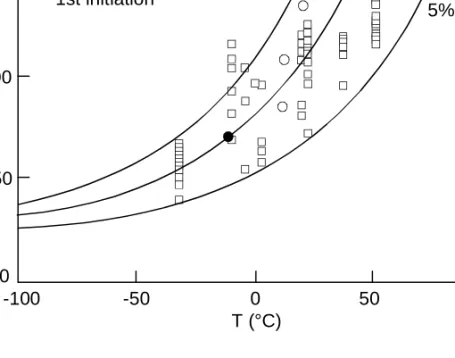
A typical example of the master curve analysis result is presented in Fig. 3 for a western pressure vessel steel. All data sets were not suitable for the master curve analysis. In many cases, the individual fracture toughness results were missing or were too scarce. Based on earlier experience, only data sets including a minimum of three proper fracture toughness results were included in the master curve analysis.
MASTER CURVE ANALYSIS OF
SA533B Cl.1 (HSST02) EPRI DATA BASE
0 100 200 300 KJC [M P a √m] 5 % 95 % FILLED POINTS NOT TRUE CLEAVAGE
3 100 MPa√ms-1, T 0=-280C 4 103 MPa√ms-1, T 0=-110C 1 105 MPa√ms-1, T 0=+30C T-T0 [°C] -100 -60 -20 20 60
Figure 3. Master curve analysis of SA 533B Cl.1 (HSST 02) EPRI data base. Filled points are not true cleavage fractures.
The Zener-Hollomon strain rate parameter is usually expressed in the form σ ε y =f ⋅ T log A . (5)
where T is the temperature in Kelvin and A is the strain rate parameter being a function of the activation energy of the yield process.
A major difference between a tensile test and a fracture toughness test is the definition of strain rate. For a crack, the stress and strain distribution is not uniform, but varies strongly in front of the crack tip. There have been attempts to prescribe a cracked specimen an effective strain rate value, but this is a very crude approximation of the real situation. Clearly better is to express the fracture mechanical loading rate in terms of the stress intensity factor and not the strain. This leads to the use of the loading rate parameter, K
.
I , in stead of the strain rate parameter,
ε
.
.
The results show that the shape of the master curve is essentially unaffected by the loading rate. Thus it is not sensible to apply the Zener-Hollomon strain rate parameter directly to the fracture toughness, but to the transition temperature T0. In this case, the strain rate parameter can be expressed as
T0 ln A I constant ⋅ ′ = K . (6)
with T0 in Kelvin degrees.
The “constant” in Eq. 6 can be expressed in terms of a reference loading rate transition temperature. A simple reference is constituted by T01 which refers to
the quasistatic loading rate
K
.
I = 1 MPa√m⋅s-1. Renaming (ln A´) as (Γ) simplifies the resulting equation to
The master curve T0 estimates were fitted with Eq. 7 in order to determine T01 and Γ for each data set. A typical result is presented in Fig. 4 for the material presented earlier. 1 10 100 1000 10000 100000 240 250 260 270 280 T0 [ K ]
SA533B Cl.1 (HSST02)
LO AD IN G RATE DEPENDENCE
(EPRI DATA BASE)
T 0 2 3 3 5 9 9 6 .7 ln K I = − . KI [M Pa√m
⋅
s-1]Figure 4. Loading rate dependence for material from Fig. 3.
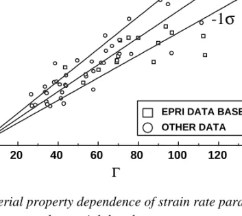
The cases where the temperature shift was less than 15°C were not included in the subsequent analysis, because the uncertainty in T0 causes the Γ estimate to be highly unreliable. Based on a simple pattern recognizing procedure, it was found that Γ can be successfully described by the yield strength and the static transition temperature and that their effect is essentially independent from each other. The best result was obtained with the equation presented in Fig. 5 and Eq. 8. Γcalc 9.9 exp T01 190 1.66 R eL 722 1.09 = ⋅ + (8)
The standard deviation of the equation is only 19.4%. The true standard deviation of the loading rate dependence expression is actually likely to be even less than 19.4%, because, it not only includes the inaccuracy of the correlation itself, but also the inaccuracy in the T0 determination. Especially for large Γ
values and small loading rate differences (small temperature shifts), the quality of the data will affect the scatter considerably. The static transition temperatures used in the fitting of Eq. 8, all correspond to subzero temperatures, but limited results on irradiated materials indicate that an extrapolation to temperatures close to +100°C is appropriate. 0 20 40 60 80 100 120 140 0 20 40 60 80 100 120 140
EPRI DATA BASE OTHER DATA ca lc Γ
-1
σ
+1
σ
Γcalc 9.9 exp T 01 190 1.66 R eL 722 1.09 = ⋅ + Figure 5. Material property dependence of strain rate parameter Γ. Boxes refer to EPRI pressure vessel material data base.
In terms of temperature shift, the accuracy is estimated to be of the order of
±20%. The combination of Eqs. 7 and 8 is shown graphically in Fig. 6 for a
dynamic loading rate of 1⋅106 MPa√m⋅s-1. As expected, the shift increases when the yield strength or the quasistatic transition temperature decreases.
DYNAMIC LOADING RATE SHIFT
OF
MASTER CURVE TRANSITION TEMPERATURE
200 400 600 800 1000 0 20 40 60 80 100 120 140 ∆T 0 [°C ] ReL [MPa] T01=-1000C -50 0 50 100 K K D S = 1 1 0⋅ 6
Figure 6. Transition temperature (T0) shift due to severe dynamic loading rate
as a function of yield strength and quasistatic transition temperature (T01).
Based on the study it can be concluded that:
• the master curve concept is applicable also for dynamic loading rate fracture toughness data,
• based on the room temperature yield strength and the “static” fracture
toughness transition temperature it is possible to describe the effect of loading rate with a ±20% accuracy,
• the loading rate dependence expression was developed for loading rates
between 1⋅10-1 - 1⋅106 MPa√m⋅s-1, strength levels between 200 - 1000 MPa and static transition temperatures between -180 - 0°C, but extrapolation to higher transition temperatures appears appropriate.
4. Miniature fracture toughness testing
One fundamental issue in fracture mechanics testing has been the definition of a specimen size, which is required for a so-called valid measurement. Theoretically, the loss of constraint at the crack tip of a small specimen can be
calculated, but so far no universal way is available for transforming the
measured fracture toughness to a standard parameter like KIC. On the other
hand, the application of constraint-based specimen size criteria leads to unrealistically large specimens, e.g., for use in reactor pressure vessel (RPV) surveillance.
According to the concept proposed by VTT, the critical value of the J-integral (J) at the onset of cleavage fracture is measured and transformed to the fracture toughness (K) which is then used in analysing the results statistically. The statistical cleavage fracture model used has been well verified for a large number of various structural steels and specimen geometries down to the 10*10*55 mm specimen size. For most structural steels the temperature
dependence of fracture toughness can be described with only one material-specific parameter, i.e. the reference temperature T0 (100 MPa√m).
The testing capabilities have now been developed further to smaller
(ultra-small) specimens, i.e. three-point-bend specimens of size 3*4*27 mm,
5*5*27 mm, 5*10*55 mm and 10*10*55 mm. This development programme was
completed in 1997 and it was followed by a test programme in order to demonstrate the restrictions and applicability of these specimens in fracture mechanics testing (Valo et al. 1997). The objectives of the programme for these ultra-small specimens were as follows:
• To assess the validity of fracture toughness data measured.
• To find approximate estimates for the measuring capacity of specimens.
• To clarify the need to have some kind of constraint correction.
• To verify the applicability of the cleavage fracture model.
As concerns testing and analysing data, there are no special restrictions or requirements in using ultra-small specimens. The test temperature should, however, be low enough to initiate cleavage fracture in the test. Due to the limited "measuring capacity", such small specimens are best suitable for characterising cleavage initiation. In the ductile area, the small ligament size does not allow sufficient crack growth in the specimen and practically only the
Two pressure vessel steels were used in the study. The first was the ASTM Round Robin exercise material, i.e. plate HSST-3 of grade A533B. The second material was VVER 440 RPV steel 15Kh2MFA (VVER), a quenched and tempered Cr-Mo-V type forging. In addition, some fracture mechanics tests with ultra-small specimens had been conducted previously with a Cr-W-V fusion reactor structural steel.
The tests were performed following ASTM E 1152-87 whenever applicable. Load, load line displacement and crack opening displacement were measured
when testing 5*10 mm, 10*10 mm and larger specimens. The crack length of a
specimen was measured during the test with unloading compliance technique and a crack growth correction was applied. The tests were continued until cleavage fracture occurred or until a practical limit of the specimen displacement was reached. A simple crack growth correction (9) was made for the small specimens based on the initial and final crack lengths measured from the fracture surfaces. The amount of this correction was in general small.
J J a W a corrected = × − × − 0 0 1 0 5 ( . ∆ ) (9)
The specimens were prepared by an electric discharge machine. They were precracked with a PC controlled device under continuous monitoring of the load and crack length. In prefatiguing Kmax of 10 - 12 MPa√m and load ratio of 0 < R < 0.1 were used. All specimens were side grooved to 2*10% after the prefatigue.
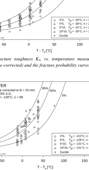
Most of the tests were performed in the transition range and ended at cleavage fracture, but some tests were also conducted in the temperature range of ductile fracture behaviour. The statistical size correction was made for the test results to convert them to the 25 mm specimen thickness. The combined (size-corrected)
fracture toughness (KJc) data and corresponding fracture probability curves
T - T0 [°C] -50 0 50 100 KJc [M Pa √ m] 0 50 100 150 200 250 300 + ++ + + Size corrected to B = 25 mm 2*10% S.G. T0,all = -33°C, n = 115 95% 50% 5% HSKALL.SPW HSST-3 3*4, T0 = -28°C, n = 35 5*10, T0 = -31°C, n = 26 10*10, T0 = -35°C, n = 31 5*5, T0 = -38°C, n = 23 Ductile +
Figure 7. Fracture toughness KJc vs. temperature measured with HSST-3
specimens (size-corrected) and the fracture probability curves. T0 (100 MPa√m)
= −33oC. T - T0 [°C] -50 0 50 100 150 KJc [M Pa √ m] 0 50 100 150 200 250 300 + 3*4, T0 = -123°C, n = 27 VVER 5% 50% 95% Size corrected to B = 25 mm 2*10% S.G. T0 = -128°C, n = 88 VVRKALL.SPW 5*10, T0 = -131°C, n = 18 10*10, T0 = -131°C, n = 20 5*5, T0 = -128°C, n = 23 Ductile +
In general, the results of the test programme were very promising, showing that the values of the 100 MPa√m level reference temperature (T0) determined even
with 3*4 mm specimens are in good agreement with those of larger specimens.
In addition, the statistical specimen size correction of the cleavage fracture model proved to be sufficient for all specimen types used, suggesting that no constraint correction is needed even with the 3*4 mm specimen.
Moreover, measurements made on the ductile area indicated that nearly similar
fracture resistance curves can be obtained with 5*10 mm and larger specimens
up to the J-level of 500 kN/m. Beyond this toughness level, curves measured with small specimens started to deviate from the curve of the larger specimen (Figs. 9 and 10). The proportional crack growth, i.e. the ratio ∆a/ligament, was a parameter limiting the measuring capacity of a specimen in the area of ductile tearing.
The study indicated that:
• Small three-point-bend specimens (3*4 and 5*5 and 5*10 mm) are applicable in
characterizing the fracture toughness in the transition region by applying the statistical cleavage fracture model of VTT, employing only the statistical specimen size correction included in the model.
• Microstructural factors do not cause excessive scatter in fracture toughness
data measured even with the smallest applied specimen (3*4 mm).
• The 5*10 mm three-point-bend specimens give fracture resistance curves
consistent with those of larger specimens (10*10 mm) up to J values of 400
∆a [mm] 0 2 4 6 8 10 JAS T M [k N /m ] 0 200 400 600 800 1000 1200 HSST-3, LT T: 20 °C 20% S.G. 5*10 10*10 10*20 B*W mm HSSTASTM.SPW 5*5
Figure 9. Fracture toughness vs. crack growth measured with HSST-3 specimens. ∆a [mm] 0 2 4 6 8 10 JAS T M [kN/m ] 0 200 400 600 800 1000 VVER BASE T: 20 °C 20% S.G. 5*10 10*10 10*20 17.5*35 B*W mm VVERASTM.SPW 5*5
Figure 10. Fracture toughness vs. crack growth measured with VVER specimens.
5. Modified crack-arrest fracture toughness
determination
A novel feature has been developed for the procedure of crack-arrest fracture toughness determination according to the standard ASTM E 1221-88, to overcome difficulties encountered in weld preparation for cleavage crack initiation in the higher transition temperature range of a bainitic pressure vessel steel.
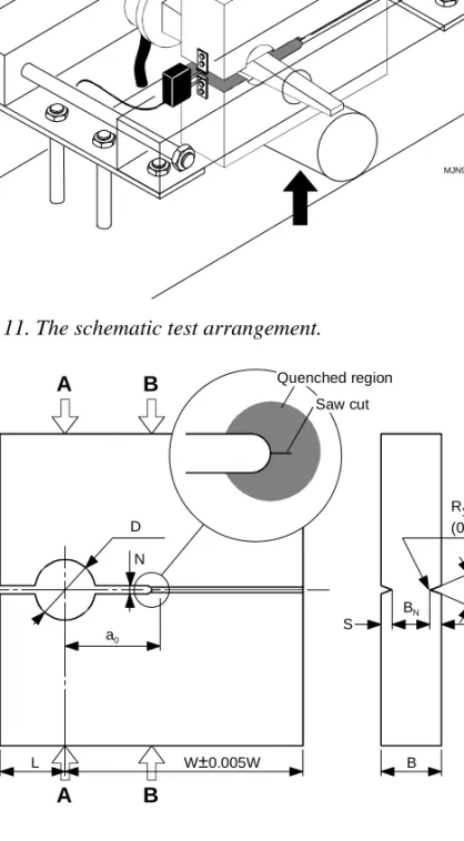
The crack initiation process zone was produced by thermal treatment to a controlled brittle state. An electron-beam welding machine was used to accurate and reproducible quenching of the notch root. No welding was applied. Some specimens were additionally given a reversed bending treatment to homogenise the residual stresses. As a result, the control of the initiation stress intensity levels was greatly facilitated. An additional deflection restraining compression to the specimen sides was optionally employed to limit crack opening and thus to arrest the cleavage crack within acceptable limits.
With this ‘restraint’ method valid test results were obtained at temperatures corresponding to the upper transition temperature region of cleavage cracking. Linear finite-element analyses were conducted to determine the effect of the specimen side compression on stress intensity factor at cleavage crack initiation and arrest (KQ, Ka).
Also, a set of instrumented Charpy tests were conducted to determine the crack arrest load as a function of test temperature for comparison to other similar materials.
The restrain method together with the developed notch root treatment provides good conditions for the crack-arrest fracture toughness determination. Results were obtained at higher temperatures than is possible, strictly following the standard procedure. This finding has been made both with a russian 15KH2MFA pressure vessel steel and previously with a tool steel. The results have been verified by comparing determined transition temperature with other, similar type of steels, and the validity has been found to be good.
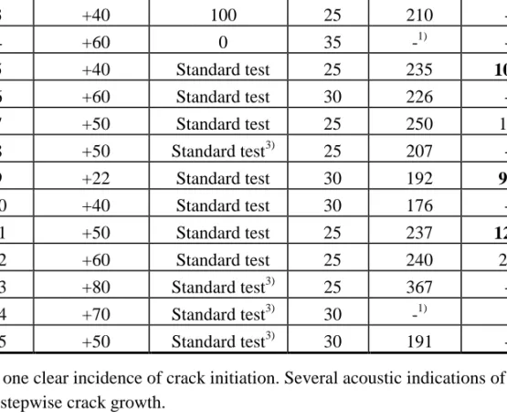
Table 1. Test results in testing order. Test either a standard test or with side-compression (restraint). Heating time refers to time under EB-heating. KQ is the
stress intensity factor at crack initiation and Ka is the stress intensity factor at
crack arrest. Test number Test temperature (°C) Standard test / Compression load (kN) Heating time (min) KQ (MPa√m) Ka (MPa√m) 1 +22 300 20 235 1104) 2 +40 300 25 225 160 3 +40 100 25 210 -2) 4 +60 0 35 -1) -2) 5 +40 Standard test 25 235 1014) 6 +60 Standard test 30 226 -2) 7 +50 Standard test 25 250 197 8 +50 Standard test3) 25 207 -2) 9 +22 Standard test 30 192 924) 10 +40 Standard test 30 176 -2) 11 +50 Standard test 25 237 1264) 12 +60 Standard test 25 240 211 13 +80 Standard test3) 25 367 -2) 14 +70 Standard test3) 30 -1) -15 +50 Standard test3) 30 191 -2)
1) No one clear incidence of crack initiation. Several acoustic indications of small stepwise crack growth.
2) Crack propagation principally in quenched region, not in virgin material. Ka -value meaningless.
3) No pre-compression of the specimen.
MJN972.dsf
Figure 11. The schematic test arrangement.
MJN971.dsf H H D N a0 L W±0.005W B S BN 45°±5° R≤0.010±0.005 in (0.250±0.125 mm) A A B B Quenched region Saw cut
0 50 100 150 200 250 300 350 400 -60 -40 -20 0 20 40 60 80 100 Temperature (°C) Toughness, (MPa √ m) KQ/Prometey KIa/Prometey ASME KIa/VTT Ka/VTT Kaest/VTT KQ/VTT20 KQ/VTT25 KQ/VTT30 KQest/VTT35
Figure 13. The results of VTT and ‘Crism’ Prometey. KQ refers to crack initiation
fracture toughness, while Ka and KIa refer to non-valid and valid crack-arrest
fracture toughness. Numbers 20-35 refer to minutes under EB-heating. ASME lower bound curve is presented for reference.
-50 0 50 100 150 -50 0 50 100 150 PRESENT STUDY 5 % 95 % TKIa = TFa4kN + 12.5 oC σ = 13.1 oC
T
Fa4kN-T
KIaT
Fa4 k N[
oC]
T
KIa[
oC]
6. Conclusions
From above, it can be concluded that the research has been highly successful. However, due to the empirical nature of some of the parameters, more work is still needed before all the present findings are suitable for codification.
7. Acknowledgements
The reported work was part of the Finnish Research Programme on the Structural Integrity of Nuclear Power Plants 1995 - 1998, subproject RAVA1 on Material Degradation in Reactor Environment. The work for Chapter 2 was completed in 1995, Chapters 3-4 in 1996 and Chapters 5-6 in 1998.
Co-operation with Rainer Rantala and Matti Ojanen from the Radiation and Nuclear Safety Authority, STUK, Ralf Ahlstrand and Jyrki Kohopää from IVO Ltd. together with Matti Valo, Klaus Rahka and many other colleagues is gratefully acknowledged.
References
ASTM E 1921-1997. Test method for the determination of reference
temperature, T0, for ferritic steels in the transition range. ASTM Books of
Standards.
Rintamaa, R. & Sarkimo, M. (Eds.). 1995. RATU - Nuclear power plant structural safety research programme 1990 - 1994, Final report. Helsinki: Ministry of Trade and Industry, 166 p. (Ministry of Trade and Industry Studies and Reports 135/1995). ISSN 1236-2352; ISBN 951-739-116-1
Rintamaa, R., von Estorff, U., Mc Garry, D., Hurst, R. C. & Wintle, J. B. 1997. Pre-test material characterization of the NESC spinning cylinder (ICONE5-2279). Proc. of ICON 5: 5th Int. Conference on Nuclear Engineering, Nice, France, May 26 - 30.
Wallin, K. & Rintamaa, R. 1995. Re-evaluation of the thermal shock experiment results based on the VTT approach for statistical treatment of fracture toughness data. 21. MPA-Seminar, Approaches to Lifetime Extension of Nuclear Power Plants, Vol. 1. Pp. 2.1 - 2.18.
Wallin, K. 1997. Effect of strain rate on the fracture toughness reference
temperature T0 for ferritic steels. In: Recent Advances in Fracture, R. K.
Mahidhara, A. B. Geltmacher, P. Matic and K. Sadananda (Eds.). The Minerals, Metals & Materials Society. Pp. 171 - 182.
Valo, M., Planman, T. & Wallin, K. 1997. The applicability of small and ultra-small fracture toughness specimens for material characterization. In: Small Specimen Test Techniques, ASTM STP 1329, W.R. Corwin, S.T. Rosinski, and E. van Walle, (Eds.). Philadelphia: American Society for Testing and Materials. (To be published).
Fracture analysis of ductile elastic-plastic
materials under mixed-mode I-II loading
Anssi Laukkanen
VTT Manufacturing Technology Espoo, Finland
Abstract
In order to evaluate the mixed-mode fracture behavior of elastic-plastic metallic materials, experimental tests and numerical calculations were carried out. Since the transition of fracture toughness between opening and in-plane shear modes with ductile materials is a question of controversy, single-edge notched bend (SENB) specimens were subjected to asymmetric four-point bending (ASFPB) to provide various mode portions using four materials: A533B pressure vessel steel, F82H ferritic stainless steel, sensitized AISI 304 austenitic stainless steel and CuAl25 copper alloy. Fracture resistance curves were determined and fractographical studies performed. Numerical studies focused on determining the J-integral and stress intensity factor (SIF) solutions for the experimental programme and the Gurson-Tvergaard constitutive model was used to simulate continuum features of the fracture process. The results demonstrate that mode II fracture toughness of ductile metallic materials can be significantly lower than mode I fracture toughness. Studies of the micromechanical aspects of fracture demonstrate the factors and variables responsible for the behavior noted in this investigation.
1. Introduction
Mixed-mode fracture research has traditionally dealt with brittle materials behaving in a linear-elastic manner. The results in case of brittle fracture (see e.g. [1-3]) have demonstrated that the mode II fracture toughness is usually
toughness, the results are not as unequivocal. Different researchers with different materials as well as experimental setups have obtained opposite and controversial results. Some researchers, e.g. [4-5], have found that in mode II fracture toughness is higher than in mode I, but other researchers have obtained inverse results suggesting that in mode II fracture toughness is lower than in mode I, e.g. [6-7]. The area of elastic-plastic mixed-mode fracture toughness suffers also from lack of studies, meaning that relatively few studies have been published. One reason for this is the difficulty associated with controlling nonlinear elastic-plastic two-dimensional situations, both in numerical simulations and in experimental work.
The basic idea and background for the question why mixed-mode fracture and fracture toughness can not be taken as conservative with respect to mode I stems from the basic thinking in mode I, which typically neglects differences in fracture micromechanisms. Since it appears that the mode II brittle fracture toughness is higher than the mode I toughness, we can think that mode II ductile fracture toughness would be higher than mode I, with the same simple analogy. This reasoning and others like it, on the other hand, lacks the information regarding the differences in fracture micromechanisms and, thus, is not correct. The right approach for brittle mixed-mode and mode II fracture is obtained when starting from the simplified result that brittle fracture is controlled by stresses, usually the hydrostatic stress or the first principal stress ahead the crack. When introducing a shear component to the crack loading, this decreases the value of hydrostatic tension and as a consequence causes an increase in macroscopic fracture toughness. But when considering ductile fracture, we are faced with a situation where the fracture micromechanisms are mainly controlled by strains. When introducing a shear-component to the crack loading we at the same time increase the values of strain when considering J2-plasticity. Because of this general and simple result, the macroscopic fracture toughness should be lower in ductile fracture and the situation has a principal difference compared to brittle material behavior.
Experimental work in the field of mixed-mode fracture has generally been quite extensive for the past few decades. Yet, several issues still remain open, and when considering ductile materials behaving in an elastic-plastic manner the results currently available are pretty scarce. Generally, several studies with ductile materials suffer from weaknesses associated with analysis of results,
meaning that very few studies have focused on characterizing the mixed-mode fracture toughness in terms of J-integral or other associated parameters. Concentrating on studies related to ductile behavior of metallic materials, Maccagno and Knott [4] used the asymmetric four-point bend (ASFPB) setup in determining the fracture toughness transition of HY130 pressure vessel steel. The study recorded the modes of fracture as well as the ductile fracture transition. The transition in micromechanical terms refers to a shear-type of crack nucleation in comparison to more typical, mode I fibrous crack extension. In a revised study Bhattacharjee and Knott [8] focused on micromechanical changes associated with different degrees of shear loading. Both studies suffered from inadequate analysis of results, i.e. the results were mostly presented in terms of load-displacement curves. Shi et al. [5] and Shi and Zhou [9] examined the fracture toughness of HT100, HT80 and A36 steels in modes I and II. They found differences in micromechanical features, as well as that in their test series the fracture toughness in mode II was higher than in mode I. Several studies suffer from uncertainties related to experimental setups (instrumentation, friction, measurement of crack length) in addition to the other weakness, analysis of results.
Numerical analysis of mixed-mode I-II crack behavior has mainly dealt with using the Gurson-Tvergaard constitutive model in simulating the effects of shear-stresses on crack nucleation behavior, if we neglect the numerous driving force solutions for different specimen geometries. Tohgo et al. [7] used the original Gurson’s model and were able to demonstrate the competition between two different nucleation processes depending on the degree of shear-loading, i.e. crack nucleation from the blunted side of the notch and from the sharpened tip. Aoki et al. [10] continued along the same lines and focused on the crack tip deformation behavior with different mode proportions. Ghosal and Narasimhan [11, 12] focused on determining the fields of equivalent plastic strain, hydrostatic tension and void volume fraction with the Gurson-Tvergaard model including nucleation and accelerated void growth after certain critical void volume fraction. They found the same results as before but most of all, they were able to present their results with better correspondence to micromechanics of fracture, priming their consideration on typical mode I type of fracture
according to porous failure criterion of the Gurson-Tvergaard model. They were able to determine the simulated fracture nucleation toughness envelope between modes I and II, and found that when the nucleation is taken to be strain controlled, the fracture toughness had a decreasing value when moving towards mode II, but near mode II it had again a rising trend due to transition to pure shear fracture. Mode II fracture toughness as given by their simulations was lower than mode I fracture toughness.
This work focuses on determining the micromechanical aspects of mixed-mode fracture, the transition of fracture toughness between modes I and II and using numerical simulations in interpreting different aspects of the fracture process. Elastic-plastic ductile materials were studied, because earlier work has provided some controversial results and in addition the background in form of micromechanical features remains quite unknown.
2. Numerical simulations
2.1 SIF and J-integral solutions
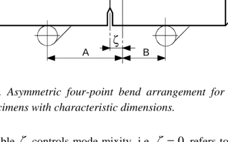
Linear-elastic two-dimensional plane strain finite element (FE) modeling was utilized in order to determine the SIF-solutions for the ASFPB-configuration. When comparing SIF-solutions available in the literature, large differences were noted (e.g. [2] contra [13]) and since the range of applicability of the results was somewhat unclear, it was found that specific analyses for the current work were required. The ASFPB-setup was chosen because of the simplicity of a bend-type specimen and is presented with its characteristic dimensions in Fig. 1.
B A
A B
W
Load line
ζ
Figure 1. Asymmetric four-point bend arrangement for single edge notched bend specimens with characteristic dimensions.
The variable
ζ
controls mode mixity, i.e.ζ =
0
refers to mode II loading andζ = ∞
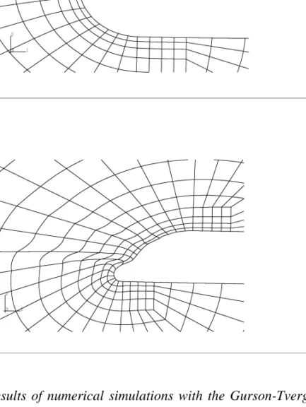
to mode I. Because measures A and B presented in Fig. 1 do not have any influence on the mode mixity, they were chosen based on suitability for experimental purposes. J-integral was calculated following the domain integral routine presented by Li et al. [14]. Because the mode mixity under different loading conditions is of interest, the J-integral must be partitioned to mode I and II contributions. This was achieved by using the filtering method presented by Mattheck and Moldenhauer [15]. The idea of the filtering technique consists of applying suitable constraint equations to reduce the situation back to either mode I or mode II loading. This is achieved with restraining the displacements either symmetrically or antimetrically, depending on whether mode I or mode II contribution is to be filtered from the total J-integral. A typical FE-mesh used in the calculations is presented in Fig. 2a. Three-dimensional calculations were performed to determine the variations of equivalent and hydrostatic stresses inthe thickness direction with different values of
ζ
, and a deformed mesh froma)
b)
Figure 2. Finite element meshes; (a) two-dimensional mesh and (b) deformed three-dimensional mesh.
In order to produce the results as a function of a single parameter depending on proportions of mode I and mode II loading, an equivalent mode angle is presented:
β
eq II IK
K
=
−tan
1 , (1)where Ki denote the corresponding SIFs. The results of the linear-elastic
calculations were fitted to polynomial form and are presented in Fig. 3a. The equivalent mode angle of eq. (1) can be given for the ASFPB configuration as
β
ζ
eq II IWY
a
W
Y
a
W
=
−tan
16
, (2)which is a necessity in controlling the experimental tests and is presented with different values of
a W
and ζ in Fig. 3b.0.3 0.4 0.5 0.6 0.7 0.8 0 1 2 3 4 5 6 7 8
mode II, finite element mode I, finite element mode I mode II
Y
I(a
/W
)
, Y
II(a/
W
)
a/W
a) 0.0 0.1 0.2 0.3 0.4 0.5 0.6 0.7 0 20 40 60 80 a/W=0.3 a/W=0.4 a/W=0.5 a/W=0.6 a/W=0.7 β eq[d
egr
ee
s]
ζ/W
b)Figure 3. Non-dimensional stress intensity factor results; (a) correction functions and (b) equivalent mode angle.
The J-integral solutions were determined according to the formalism presented by Rice et al. [16]. The
η
i-factors for modes I and II were determined based on an ideal-plastic material model and are presented in Fig. 4.0.0 0.1 0.2 0.3 0.4 0.0 0.5 1.0 1.5 2.0 2.5
Mode I, finite element Mode II, finite element Mode I Mode II
η
I,
η
IIζ/
W
Figure 4. ηi-solutions for J-integral determination.
The calculations required great concern and exact interpretation of results, because of the two-dimensionality of the deformation field. Since the behavior under mixed-mode loading is neither symmetric nor antimetric, effects such as friction must be considered when the solution is compared to realistic behavior. These additional boundary conditions need to be examined during calculations to form physically sound solutions. The assumptions made regarding the ideal-plastic material behavior were verified using incremental ideal-plasticity analysis and the assumptions were found valid within the range of observation. Three-dimensional results presented the uniform decay in the state of hydrostatic tension ahead the crack front while the deviatoric stress state remained in proportion nearly constant at a fixed observation point ahead the crack tip.
![Figure 9. Fracture toughness vs. crack growth measured with HSST-3 specimens. ∆a [mm]024 6 8 10JASTM [kN/m]02004006008001000VVER BASET: 20 °C20% S.G.5*1010*1010*2017.5*35B*W mmVVERASTM.SPW5*5](https://thumb-us.123doks.com/thumbv2/123dok_us/10731673.2961371/38.892.244.620.317.1041/figure-fracture-toughness-growth-measured-specimens-jastm-mmvverastm.webp)