Chapter 6: Lighting control systems
Topics covered
6 Lighting control systems ... 139
6.1 Introduction ... 139
6.2 Identification of the lighting control needs ... 140
6.2.1 Specification book ... 141
The building owner needs an efficient lighting system ... 141
The occupant needs to control the system ... 141
The occupant needs to understand the system ... 141
The lighting control system must be easy to use... 141
6.3 Suitable Lighting Control Strategies ... 142
6.3.1 Introduction... 142
6.3.2 Predicted occupancy control strategy... 144
6.3.3 Real occupancy control strategy (ROCS) ... 145
6.3.4 Constant illuminance control strategy... 146
6.3.5 Daylight harvesting control strategy ... 146
6.3.6 Lighting management system and building management system ... 147
6.3.7 Lighting control integration levels ... 148
Level 1 (artificial lighting alone) ... 148
Level 2 (artificial lighting control based on external information)... 149
Level 3 (artificial lighting and daylight and HVAC system) ... 149
Sharing of equipment and sensor ... 151
6.3.8 Lighting control strategy analysis ... 152
6.4 Lighting control architecture ... 153
6.4.1 Lighting control levels ... 153
Plant Control Architecture ... 153
Zone Control Architecture ... 154
Wiring Device Control Architecture... 155
Embedded Fixture Control Architecture... 155
Architecture SWOT Analysis ... 156
6.4.2 Lighting control components ... 157
Controllers ... 157
Actuators ... 161
Networks ... 163
Component analysis ... 169
6.5 Recommendations ... 169
6.6 Illustrations... 172
6.6.1 Illustration 1: NOSS National Office for Social Security – Belgium ... 172
Control and management of the daylight ... 172
Control and management of the artificial light ... 172
6.6.2 Illustration 2: The Berlaymont Building - a louvres façade – Belgium ... 173
Façade description ... 174
Control and management of the daylight ... 174
Control and management of the artificial light ... 176
6.6.3 Illustration 3: Intecom project - France... 176
6.6.4 Illustration 3: DAMEX project - Finland... 178
6.7 Conclusions ... 180
6
Lighting control systems
6.1 IntroductionA building can be compared to a system with a variety of physical processes interacting with each other and with the environment. From the control point of view, it is considered as having multi-variant dynamic subsystems showing linear or non-linear behaviours. Environmental and occupancy changes in a building increase the complexity of control operations. Occupants not only impose control goals related to thermal comfort, visual comfort or indoor air quality but also influence the building processes impacting indirectly on the control functions of the different processes (HVAC, lighting, etc.).
Due to the increase of environmental concerns, lighting control systems will play an important role in the reduction of energy consumption of the lighting without impeding comfort goals. As mentioned in the IEA Annex 31 (IEA 2001), energy is the single most important parameter to consider when assessing the impacts of technical systems on the environment. Energy related emissions are responsible for approximately 80% of air emissions (IEA 2001), and central to the most serious global environmental impacts and hazards, including climate change, acid deposition, smog and particulates. Lighting is often the largest electrical load in offices, but the cost of lighting energy consumption remains low when compared to the personnel costs. Thus its energy saving potential is often neglected. According to an IEA study (IEA 2006), global grid based electricity consumption for lighting was about 2650 TWh in 2005, which was an equivalent of 19% of total global electricity consumption. European office buildings dedicate about 50% of their electricity for lighting, whereas the share of electricity for lighting is around 20-30% in hospitals, 15% in factories, 10-15% in schools and 10% in residential buildings ( EC 2007).
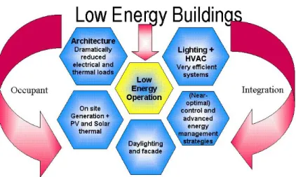
Figure 6-1. Low energy building concept.
The human requirements and the quality of the working environment are often expressed in terms of thermal and visual comfort. The optimal conditions of thermal comfort can be easily described as the neutral perception of the interior environment, where occupants do not feel the need for change towards warmer or colder conditions. Visual comfort, however, is not described easily. Rather than referring to a state of neutral perception of the interior environment, it is perceived as receiving a message. Aspects such as daylighting, glare, luminance ratios, light intensity and contact to the outside have their influences on our perception of visual comfort.
To fulfill the the requirements about comfort and energy efficiency, building managers have implemented programs to reduce lighting energy requirements by installing more efficient light sources and luminaires. However, this is not sufficient. Lighting energy management has to provide the optimal lighting level for the tasks being performed using the most efficient light source suitable for the application, and providing light only when and where it is needed. This can be achieved by using lighting control strategies and lighting control system. The main purpose of these systems is to reduce energy consumption while providing a productive visual environment. This includes:
― Providing the right amount of light ― Providing that light where it’s needed ― Providing that light when it’s needed
In fact, lighting control will depend on the considered zone. Thus, it is necessary to define the following factors beforehand:
― The lighting needs (level of illumination, ambience, etc.) ― The task zone/area (position, size, disposition, etc.) ― The occupation time
― The control needs of the user 6.2 Identification of the lighting control needs
Development of a questionnaire for users
Lighting control is continuously evolving due to the constant evolution of requirements for visual comfort and the increasing demand for lighting energy savings. But there is often a lack of a clear identification of the needs. Annex 45 proposes hereby a questionnaire in order to help the designer to identify the needs so that optimized solutions can be adopted. Note that the identification of the person answering the questionnaire is useful to understand the needs : a building energy manager pays more attention to the energy consumption and the energy savings than the occupant. The questionnaire available in appendix B should provide information on:
― The different practices within the building ― The perception of the control barrier’s ― The needed control type
― The controlled area
― The flexibility and modularity of the lighting control system
For example, the identification of the usages helps the designer to understand the way he has to design the installation. In a school, an On/Off system coupled with daylight dimming may be adequate but in some offices, it could be necessary to go one step further by integrating more advanced techniques. Similarly, asking the perception of the people on the barriers of lighting control may give information about the type and quality of lighting control system that can be applied (basic On/Off switching system, advanced daylight dimming system, etc.). It is also important to collect information about:
― Flexibility and modularity of the lighting system which gives information about the future affectations of the building. For some buildings (e.g. rented offices) light structure walls are displaced and spaces are reorganized regularly. A change of the lighting control system then has to be possible and easy.
6.2.1 Specification book
The building owner needs an efficient lighting system
An objective evaluation of a system requires the definition of performance parameters. In addition, it depends on baseline conditions to which the performance should be compared. Performance parameters include:
― Visual performance and comfort ― Building energy use
― Cost effectiveness ― Ease of use ― Maintenance
― Flexibility (versatility) ― Existing building constraints ― System stability
― Systems integration
An optimal system performance needs not only to reach a good performance with respect to saving electrical energy, but also to be accepted by the end-user. The end-user may be disturbed by the operation of the system and disable it. A high user acceptance guarantees undisturbed operations and consequently energy savings. Existing buildings have specific constraints and requirements. There is a need to analyze the existing lighting system and to determine the upgrade possibilities considering the technical and economical constraints. Therefore, an audit of the existing lighting installation is necessary. Advanced control requires elements such as electronic dimmable ballasts and distributed electric indoor grids. Similarly, the use of wireless technologies (switches, sensors, etc.) is a suitable solution for retrofit so that the placement and exploitation costs can be limited.
The occupant needs to control the system
Within the limits of comfort, it is difficult to define exactly what the needs and priorities of the occupant are. They vary from one occupant to another, and also with time for the same occupant. For instance, some occupants may be concerned by energy savings, and some prefer better algorithmic lighting scenes even if it requires more energy and generates higher costs. Therefore, it is recommended that the occupant should have the possibility to change the system’s behaviour according to his will.
The occupant needs to understand the system
The user acceptance of a lighting control system is better if the system and its working principle have been explained. On-site visits by practitioners and informal discussions with end-users showed that about 90% of them accept the system operation if they know/understand what its aims and working principles are. It has also been demonstrated that occupants react to a need (a specific condition) but not necessary to the disappearance of this need. For example, if an occupant switches on the lights due to a sudden obstruction of the sun, the probability that he will switch off when the high daylight levels have turned low.
The lighting control system must be easy to use
The usability of the system must be defined to address all the types of users (building operators, occupants, facility managers, maintenance teams, installers, etc.). Usability expresses the quality of the experience of an user when interacting with a system.
It is the combination of factors affecting the experience of the user with the product or system: a. Ease of learning
― How quickly can an untrained user learn to operate the system sufficiently well?
b. Efficiency of use
― How well and fast can an experienced user carry out tasks using the system?
― What about the required time for servicing and maintenance ? c. Error frequency and severity
― How often do users make errors when operating the system?
― How severe are these errors and how easily can they be detected and corrected?
d. Subjective satisfaction
― Does the user feel comfortable with the system ?
― Does the user feel that using the system brings any advantages ? ― In what way does he interacts with?
e. Maintenance
― What about determination and implementation of the maintenance schemes ?
6.3 Suitable Lighting Control Strategies
6.3.1 Introduction
Lighting and lighting control represents a significant contribution to the energy consumption of building. In order to estimate the lighting energy consumption and related impact of controls the simplified equation from the European standard EN 15193 could be used:
t P t L W W W = , + , (kWh) (6-1) Where
W - Total energy used for lighting - the amount of energy consumed in period t, by the luminaires when operating, and parasitic loads when the luminaires are not operating, in a room or zone, measured in kWh.
WL,t- Energy consumption used for illumination - the amount of energy consumed in period t, by the luminaires to fulfill the illumination function and purpose in the building, measured in kWh.
WP,t- Luminaire parasitic energy consumption - the parasitic energy consumed in period t, by the charging circuit of emergency lighting and by the standby control system controlling the luminaires, measured in kWh.
(
) (
[
) (
)
]
{
}
∑
× × × × + × = n O N D O D c n t L F t F F t F P W 1000 , (kWh) (6-2) WheretD– Daylight operating hours.
tN- Non-daylight operating hours.
Pn–Total installed lighting power, measured in watts.
FD-Daylight dependency factor - factor relating the usage of the total installed
lighting power to daylight availability in the room or zone.
lighting power to occupancy period in the room or zone.
FC- Constant illuminance factor- the factor relating to the usage of the total installed
power when constant illuminance control is in operation in the room or zone.
The estimation of the parasitic energy (WP,t) required to provide charging energy for emergency
lighting and for standby energy for lighting controls in the building is established using the following equation:
(
)
[
]
{
}
(
)
{
}
∑
× − + + × = 1000 , e em N D y pc t P t P t t t P W (kWh) (6-3) Wherety- Standard year time - time taken for one standard year to pass, taken as 8760h. tD– Daylight hours - the operating hours during the daylight time.
tN- Non-daylight hours - the operating hours during the non-daylight time.
te- Emergency lighting charge time - the operating hours during which the emergency lighting batteries are being charged in hours.
Ppc- Total installed parasitic power of the controls in the room or zone - the input power of all control systems in luminaires in the room or zone, measured in watts.
A detailed description of these equations is given in Annex 4 : EN 15193.
The reduction of the energy consumption is possible by playing on the different elements of the equations, for example:
― The installed power can be reduced by using low consumption light sources and efficient control gear (electronic ballasts, electronic DC transformer, etc.).
― Daylight dimming can lead to an important reduction of the energy consumption by adjusting the light flux smartly according to the daylight level. This is what is done by the FDparameter.
― Operating hours can be reduced by adjusting lighting according to predicted or real occupation strategies through the FO parameter and the amount of working hours (tN and tD). In fact, only a fraction of a building’s lighting system is required at any given time. Lights frequently are left on in unoccupied places where there is no need for lighting Through the reduction of the tN, tDand FO values, energy savings can be calculated.
The first lighting controls level, also the most widely used, is the manual switch to put on or off an individual luminaires or a group of luminaires. This type of control is not robust enough with respect to energy efficiency as it relies solely on the behaviour of the occupants who are not necessarily concerned by energy savings, especially in the tertiary sector buildings. Lighting control strategies provide additional cost-savings through real time pricing and load shedding. Reducing lighting power during electricity peak-use periods when energy rates are at the highest can also be achieved through a Lighting Management System (LMS).
Lighting Management Systems allow building operators to integrated lighting systems with other building services such as heating, cooling, ventilation, in order to achieve a global energy approach for the whole building, in particular for green building or an energy-producing building.
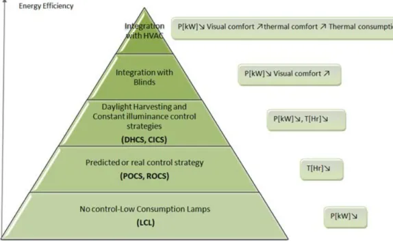
Energy efficiency of lighting control systems depend on the strategies implemented as presented in figure 6-2.
Figure 6-2. Relation between control strategy and energy efficiency.
6.3.2 Predicted occupancy control strategy
The Predicted Occupancy Control Strategy (POCS) is used to reduce the operating hours of the lighting installation. It generates energy savings by turning lighting on and off on a preset daily time schedule. Schedules usually vary on a daily basis according the building occupancy. By automatically turning off lights at a preset time, the systems assist building operators /facility managers to avoid having the lighting be on during unoccupied hours, mainly at night and at weekends. Different schedules can be programmed for different areas of the building based on the occupant needs.
Figure 6-3. Time scheduling control scheme.
The time scheduling control strategy enables switching on or off automatically based on time schedules and occupancy patterns for different zones. Twenty-four hour timers allow the occupants to set certain times for lighting. The timer is set to switch lighting on during occupancy. Measurements have shown that the best energy efficient solutions are combining the use of a cut off system with a manual switch on system; potential gains are between 10 and 15% (without
daylighting) (Floyd et al. 1995, Rundquist et al. 1996). Note that the gain may be more than 50% in case of 24 hours lighting (Maniccia et al. 1999, NBI 2003).
This strategy is used most widely in applications where building occupancy patterns are predictable and follow daily and weekly schedules like classrooms, meeting rooms and offices.
Figure 6-4. Dusk dawn control scheme.
The Dusk or Dawn control strategy is a type of predicted occupancy strategy based on sunrise and sunset which can be calculated for every building location. Light is switched on automatically when it gets dark, and off when there is enough daylight. This control type is not often applied for indoor lighting but is very efficient for atriums with good daylight availability or for glazed corridors linking buildings. This strategy is not necessarily achieved with an outdoor daylight sensor. The on and off hours can be provided by a scheduler.
6.3.3 Real occupancy control strategy (ROCS)
Real Occupancy Control Strategy limits the operation time of the lighting system based on the occupancy time of a space. In opposition to the predicted occupancy control, it does not operate by a pre-established time schedule. The system detects when the room is occupied and then turns the lights on. If the system does not detect any activity in the room, it considers the room as unoccupied and turns the lights off. To prevent the system from turning the lights off while the space is still occupied, a delay time (ranging typically from 10 to 15 minutes) can be programmed.
Figure 6-5. Occupancy control scheme.
Real Occupancy Control Strategies are best used in applications where occupancy does not follow a set schedule and is not predictable. Classic app-lications include private offices, corridors, stairwells, conference rooms, library stack areas, storage rooms and warehouses. The savings potential of real occupancy control varies widely from 20 to 50% (system combination) (Maniccia
et al. 2000, NBI 2003). It depends on the level of detection, the place of the sensor, the coupling with daylight-harvesting and of course the movements of the occupants.
6.3.4 Constant illuminance control strategy
The Constant Illuminance Control Strategy (CICS) takes into account the ageing of the lighting system in the room. It compensates the initial oversizing of the lighting system introduced by the use of the maintenance factor (MF) at the design stage.
Figure 6-6. Constant illuminance control scheme.
The constant illuminance control strategy uses a photocell to measure the lighting level within a space or determines the predicted depreciation (ageing) of the lighting level. If the light level is too high, the system’s controller reduces the lumen output of the light sources. If the light level is too low, the controller increases the lumen output of the light sources. The result is a system that minimizes lighting energy use while maintaining uniform and constant lighting levels.
6.3.5 Daylight harvesting control strategy
The Daylight Harvesting Control Strategy (DHCS) allows facilities to reduce lighting energy consumption by using daylight, supplementing it with artificial lighting as needed to maintain the required lighting level.
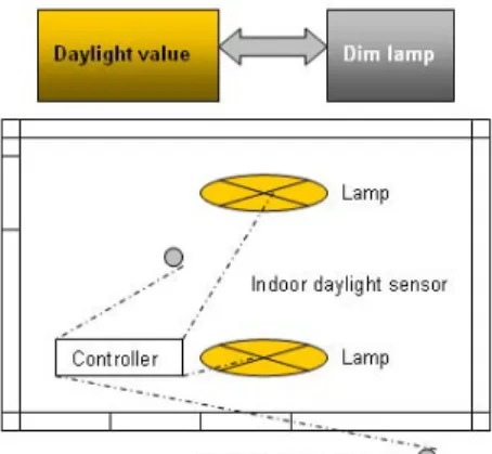
Figure 6-7. Daylighting harvesting control scheme.
The Daylight harvesting control strategy uses a photocell to measure the lighting level within a space, on a surface or at a specific point. If the light level is too high, the system’s controller reduces the lumen output of the light sources. If the light level is too low, the controller increases the lumen output of the light sources. Sensors are often used in large areas, each controlling a separate group of lights in order to maintain a uniform lighting level throughout the area. The result is a system that
minimizes lighting energy use while maintaining uniform lighting levels. This system can also provide the constant illuminance strategy.
Daylight harvesting systems are generally used in spaces that have relatively wide areas of windows or skylights. Typical applications include classrooms, high-rise office buildings and retail facilities. The savings potential varies from 20% harvesting alone) to more than 50% (daylight-harvesting plus real occupancy. (NBI 2003)
To illustrate the potential gain obtained with these different strategies an office building has been simulated according to the energy calculation method described in French regulation RT2005. Tests have been done for two climatic zones - Paris and Nice - on a 600 m² office building. The results are shown in Figure 6-8.
Figure 6-8. Estimation of energy savings according to the French thermal regulation calculation tool "method
Th-CE".
In office buildings, predicted occupancy control strategy (based on scheduler) allows 10% gain whereas real occupancy (based on presence detector) allows 20% gains. We can notice that Daylight-harvesting impact depends on the climatic zone. So, in office building potential gains vary from 30% (Paris) to 40% (Nice). Coupling of different strategies should result in more energy gains, for instance, daylight harvesting and real occupancy achieves up to 50% gains. These gains are function of the room and window sizes, building orientation and sensor(s) position(s).
6.3.6 Lighting management system and building management system
All the strategies described above can be applied in almost any building. They can be stand alone systems or part of a fully interoperable lighting management system (LMS). With LMS one can schedule the light operations in any area within the building, or monitor occupancy patterns and adjust lighting schedule as required. The LMS gives facility managers the ability to remotely control building lighting energy consumption. It also enables the facility manager to perform load shedding strategies in case of high electricity demand in the building. The utilization costs is thus reduced as the control strategy has turned off or dimmed some lights or lighting components during peak-use periods.
Moreover, thanks to LMS, building operators will be able to record lighting scenes or predefine scenarios. For instance, a simple push on a button could select a video projection scenario which would consist of dimming light level, lowering blinds and setting down the screen.
LMS also give a finest way to control lamps. Building operators will be able to manage lamps in one zone independently. The lighting rows close to the windows (usually less than 4m as best practice) will be controlled with daylight strategy whereas the others will not be. An additional advantage of LMS is their ability to monitor the operation of the lighting systems such as the number of operating hours in a given area, the number of times the lights are switched on. Using this information, maintenance operation like relamping (action to replace a burned out lamp) can be scheduled.
In case of implemented Building Management System (BMS), the management of the lighting system can be combined with heating, ventilation, air conditioning, security, etc. This type of integrated management system will allow sharing actuators and sensors. Some examples of integration are given below.
6.3.7 Lighting control integration levels
Three levels of integration can be distinguished for the indoor lighting control.These are listed below:
― The first level takes into account the artificial lighting alone.
― The second level takes into account artificial lighting and its control by external information like daylighting, occupancy,..
― The third level takes into account artificial lighting dealing with artificial lighting plus external interaction with external elements like HVAC systems and blinds.
Level 3
Level 2
Level 1
Figure 6-9. Levels of integration strategies.
Level 1 (artificial lighting alone)
In this integration example, the user controls the artificial lighting through a manual switch/dimmer.
This allows artificial lighting control according to a manual switch (ON/OFF or dimming). This solution is one of the most used systems in building consisting of only a switch for a lamp or a group of lamps.
Level 2 (artificial lighting control based on external information)
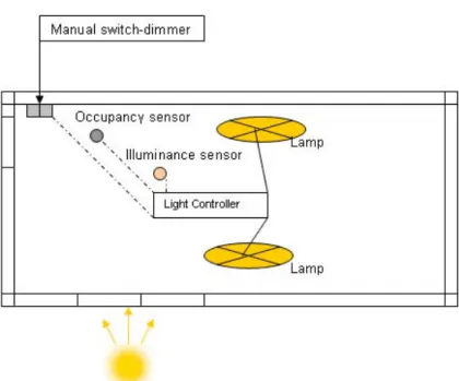
In this integration example, an illuminance sensor and an occupancy sensor have been combined to the manual switch-dimmer in order to increase the visual comfort of the occupant. For each sensor, a priority level is set.
Figure 6-11. Coupling between Artificial lighting, daylighting and real occupancy.
This system allows artificial lighting control according to:
― A manual switch (on/off) or dimming with a high priority level ― An occupancy sensor with an intermediate priority level
― An illuminance sensor (in order to assume a constant light level) with a low priority level
We can notice that the plan becomes rather more complicated when we want to share sensors. The saving potential of this solution is quite the same as daylight harvesting plus occupancy sensor.
Level 3 (artificial lighting and daylight and HVAC system)
In this integration example, there is a full integration of the lighting system with the HVAC systems and the blinds system in order to increase the visual and thermal comfort of the occupant.
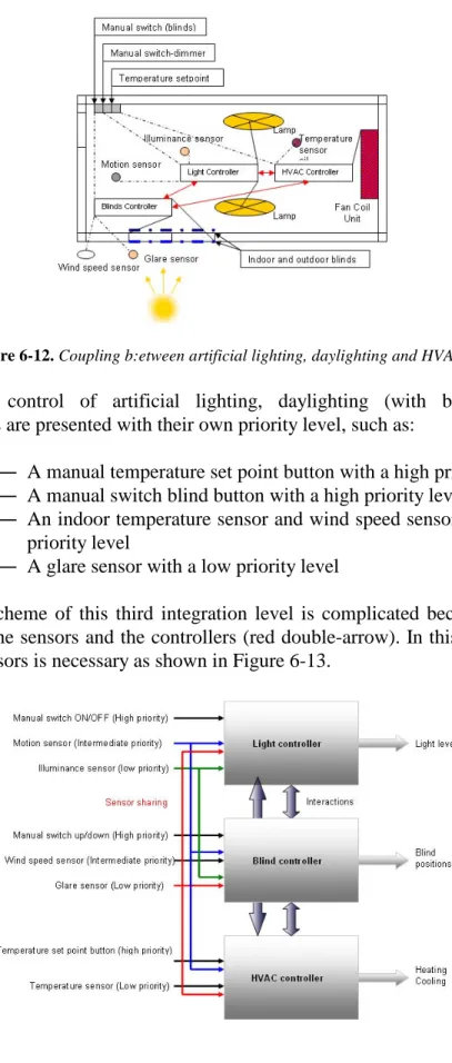
Figure 6-12. Coupling b:etween artificial lighting, daylighting and HVAC.
This system allows control of artificial lighting, daylighting (with blinds) and HVAC. Supplementary sensors are presented with their own priority level, such as:
― A manual temperature set point button with a high priority level ― A manual switch blind button with a high priority level
― An indoor temperature sensor and wind speed sensor with a intermediate priority level
― A glare sensor with a low priority level
The communication scheme of this third integration level is complicated because of the multiple interactions between the sensors and the controllers (red double-arrow). In this system, the sharing of equipments and sensors is necessary as shown in Figure 6-13.
Figure 6-14. Example of interactions between controllers.
Figure 6-14 represents the possible interactions between the different controllers. Contradictory situation may lead to problems. A blind-up request from the HVAC controller and a blind-down request from the light controller have to be solved by an arbitration system to adapt the best solution in function of predefined priorities. If correctly implemented, the energy saving potential of this integration level is more significant than a level 2 integration solution with daylight harvesting alone.
It is important to note that this kind of integration is not designed for buildings which consume large amount of energy (other cheaper solutions are, mostly, more relevant and less expensive). Nevertheless, it seems to be a real challenge to reach the requirements of new building generations (Green building and in positive energy building).
Sharing of equipment and sensor
The equipment sharing is an important issue to achieve a proper integration of the control strategies (level 1 to 3). In order to maintain a good indoor climate, the control system can generally act on the applications as shown in Table 6-1.
Table 6-1. Equipments and sensors involved in the control strategies – impact classification.
Sensor Equipment Temperature sensor Indoor illuminance sensor Outdoor illuminance sensor Occupancy sensor Solar protection system Visual comfort SA Thermal comfort MA Visual comfort MA Thermal comfort SA Visual comfort MA Thermal comfort SA -Artificial lighting system
- Visual comfort MA Visual comfort MA Visual comfort MA
Thermal comfort MA Heating system Thermal comfort MA - - Thermal comfort MA Cooling system Thermal comfort MA - - Thermal comfort MA
6.3.8 Lighting control strategy analysis
Table 6-2. Lighting control strategy analysis 1.
Strategy Predicted occupancy Real occupancy Constant
illuminance
Daylight harvesting Main
Advantages
-Low costs
-Easy to install and use
- 10 to 20 % gain
-Relatively low costs
-High rate of energy saving for space with intermittent occupation for example when people regularly go through(20 to 50%1). -Constant light level considering aging. - 5 to 15% gain -Constant light level. -Possibility to Couple with Blind and HVAC - 20 to 50% gain. Main Disadvantages -Setting of clock has to be changed if operating hours change. -Ultrasonic sensor can be fooled by HVAC systems (vibration of air flow) -low precision sensors will cause uncomfort for the occupant. -Sometimes high costs. -Not easy to configure. -Sometimes high costs. -Not easy to configure. Main Usages -Classrooms, -Meeting rooms -Offices (open space). -Store, supermarket -Museum -Corridors, stairwells -library stack areas, -Storage rooms -Warehouses -Toilet. -Offices (open space), - Classrooms, - High-rise office buildings - Retail facilities. - Offices (open space), - Classrooms, - High-rise office buildings - Retail facilities. Basic Components -Scheduler -Time clock -Switch -Dimmer -Occupancy sensor (Infra red or/and
ultrasonic) -Switch -Dimmer -Photosensor -Dimmer -Photosensor -Dimmer -Multi - switch
Table 6-3. Lighting control strategy analysis 2.
Strategy Level 1 : Artificial lighting alone
Level 2 : Artificial lighting control based on external information
Level 3 : Artificial lighting and daylight, and HVAC system
Complexity - Low - Intermediate - High
Potential of energy saving
- Intermediate - High - High
Control strategies involved - Predicted occupancy - Real occupancy - Predicted occupancy - Real occupancy - Constant illuminance - Daylight harvesting (main)
- Predicted occupancy - Real occupancy - Constant illuminance - Daylight harvesting (main)
LMS - No LMS or BMS
needed
- LMS
- BMS (optional) - BMS needed
6.4 Lighting control architecture
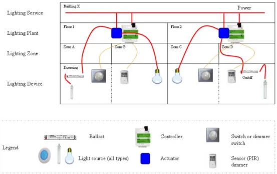
The lighting control architecture supports the implementation of the defined strategies. It can be organized in four levels:
― Lighting service ― Lighting plant ― Lighting zone ― Lighting device
The lighting service level deals with the overall lighting management system, it could also be called the lighting backbone. Lightingplant as an analogy to HVAC central plant deals with the control of central technical areas. It often appears at each building floor. Lighting zone deals with the different interactions in a zone (zone = a room or a set of rooms). Finally, lighting device is the terminal device, which controls the visual comfort of a specific area.
Plant control Zone control Wiring device control Embedded device control
Figure 6-15. Level structure of the lighting control architecture.
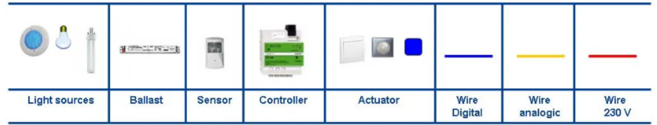
These levels have been established thanks to a study of the various lighting systems. These systems are described with generic component listed in Figure 6-16.
Figure 6-16. Lighting components.
The key point of lighting architecture definition is the position of the actuator. We can consider any lighting fixture as one or a mixed of these architectures.
6.4.1 Lighting control levels
Plant Control Architecture
The Plant Control Architecture (PCA) is an architecture where actuators and controllers are placed in one panel board at the lighting plant level. This type of architecture is usually used for on/off control in buildings like industrial buildings, supermarket. It could also be used for specific zones, for example, a complete storey in an office building, or even for individual corridors or staircases. This architecture is simple and robust and thus widely used.
Figure 6-17. Plant control.
Zone Control Architecture
The Zone Control Architecture (ZCA) is an architecture where the actuator and controller act on a defined area of the building floor. This architecture is widely used for offices with open spaces, schools and hospitals because it enables easy changes of the control strategy.
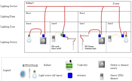
Wiring Device Control Architecture
In the Wiring Device Control Architecture (WDCA), the actuators are located at the wiring device level. It can be a wall, ceiling or floor wire. The actuator is usually embedded with the sensors. This kind of architecture is most popular for residential buildings, small offices and hotels because commands are distributed in the room to allow the occupant to perform fine control. This architecture is commonly used for simple control. Nevertheless, there exists more integrated dimming applications. Moreover, WDCA can easily be combined with plant control architecture.
Figure 6-19. Wiring device control.
Embedded Fixture Control Architecture
The Embedded Fixture Control Architecture (EFCA) is an architecture where actuators and controller are positioned in the lighting device, usually in the ballast. Most of the EFCA systems are connecting all control gears through a BUS system. They provide individual or mutual control thanks to controllers that are commonly placed at the floor panel board, in the false ceiling or in a device. On one side the binding between device is physical through, for example, wiring. On the other side, the binding is logical, through for instance, links between the push buttons, sensors (PIR) and the actuators are set by the controller. The logic behind the binding and the programming makes configuring the system really flexible and versatile. This kind of architecture uses proprietary or open networks protocols2like KNX, LON, Zwave and of course the well-known DALI.
In Figure 6-20 protocols are represented with a blue line. Some BUS system can directly provide power to the lamp (like LED), they are called Power Over BUS.
Figure 6-20. Embedded Device control.
Architecture SWOT Analysis
Table 6-4 presents the SWOT Analysis of the lighting control architecture. (The SWOT analysis is a strategic planning method used to evaluate the Strengths, Weaknesses, Opportunities, and Threats of elements or strategies).
Table 6-4. SWOT analysis of lighting control architectures.
Architecture Costs Flexibility Easy to
install
Mixing with BMS
Visual performance and comfort
Plant Control Intermediate Intermediate Quite easy Possible Low
Zone Control Intermediate Intermediate Easy Quite easy Intermediate
Wiring Device Control
Low Low Very easy Difficult Intermediate
Embedded Fixture Control
High High No expert is
needed
6.4.2 Lighting control components Controllers
A lighting controller is an electronic device used in building to control the operation of one or multiple light sources at once. Majority of lighting controllers can control dimmers which, in turn, control the intensity of the lights. Other types of controllers can also control lighting, according to specific scenarios. Lighting controllers communicate with the dimmers and other devices in the lighting system via an electronic control protocol (DALI, DMX, ZigBee, KNX, etc.). The most common protocol used for lighting today is Digital Addressable Lighting Interface which is commonly known as DALI. Controllers vary in size and complexity depending on the types of buildings (from small residential buildings to big tertiary one). For most of the time the purpose of lighting controllers is the same: to combine the control of the lights into an organized, easy-to-use system, and to reduce lighting energy consumption.
Figure 6-21. Lighting controllers.
Sensors
A sensor is a device that measures or detects a real-world condition, such as motion or light level and converts the condition into an analog or digital representation. The sensor specifications include performance factors (range, accuracy, repeatability, sensitivity, drift, linearity and response time) and, practical and economical considerations (costs, maintenance, compatibility with other component and standards, environment and sensibility to noise).
Illuminance sensor
Illuminance sensors indicate the illuminance level in the sensor detection area. They are used to measure indoor illuminance (e.g. on a working plane) and outdoor illuminance (e.g. on the roof of a building). Illuminance sensors are mostly used to switch or to dim luminaires. Some basic illuminance sensors enable day/night detection. They can also be used in integrated control strategies, particularly if solar protections are involved.
Illuminance sensor commands the lighting control system to dim or to switch on/off according to the daylight level. Illuminance sensors have to be placed so that they measure the light levels which are representative of the space. It is useful to mark the Illuminance sensor position in the lighting control panel so that building operators can find them in the future.
Figure 6-22. Example of indoor illuminance sensor.
Outdoor illuminance sensors measure the outdoor illuminance level. They can be combined with the lighting control so that indoor luminaires can be controlled by dimming or switching.
Table 6-5. Illuminance sensor – Input/Output and applications.
Component Information Inputs/Outputs Applications in buildings
Indoor illuminance sensor
Input : Illuminance on the work plane Output : Analogue or/and digital signal to controller
Visual comfort Energy consumption Outdoor illuminance
sensor
Input : Outdoor illuminance
Output : Analogue or/and digital signal to controller
Energy consumption.
Particular case of day/night sensors
This device enables the comparison of outdoor illuminance with a predefined threshold in order to trigger actions on outdoor lighting (street lighting) or closing of shutters. They were developed primarily for street lighting and are generally very robust.
Figure 6-23. Example of day/night sensor.
Table 6-6. Illuminance sensor – Input/Output and applications.
Component Information Inputs/Outputs Applications in buildings
Day/night sensor
Input : Outdoor illuminance
Output : Analogue or/and digital binary signal (on-off)
Visual comfort (outdoor lighting, shutters, etc.) Energy consumption (blinds, heating, etc.)
Presence sensors
Presence sensors detect the presence of occupants by detecting their movements. The most common sensors used in the building sector are passive infrared (PIR) sensors that react to variations of infra-red radiations due to movement of persons.
Table 6-7. Presence sensor – Input/Output and applications.
Component Information Inputs/Outputs Applications in buildings
PIR sensor Input : MovementOutput : Analogue or/and digital binary signal (occupied/not occupied)
Security Visual comfort Energy consumption
Passive InfraRed (PIR) sensor
These sensors are usually equipped with Fresnel lenses that define the zone of detection. Two kinds of PIR are usually distinguished: the movement sensor and the occupancy sensor. They have the same working principle but differ on the number of scanned areas.
Figure 6-24. PIR sensor. Figure 6-25. Multi-function PIR sensor.
Multi-function PIR sensor can integrate up to 4 functions listed below: ― Occupancy detection
― Indoor illuminance sensor (level of illuminance for the switch on of the lamps)
― Infra-red sensor
― A timer (turn the lamps off after a certain delay) The PIR sensors have some inconveniences, such as:
― Some human activities are achieved without any movement. e.g. watching television, reading book, sleep, etc.
― They are position sensitive and may be irrelevant if looking to a dead zone
Active InfraRed (AIR) sensor
Active InfraRed devices use infrared technology consisting of an infrared diode which constantly or episodically sends infrared rays into the controlled area. A receiver monitors the reflected wave levels. The non-appearance of a reflected ray or a modification of its properties (wavelength or amplitude) indicates a change occurred in the detection zone.
Figure 6-26. Infra red sensor.
Ultrasonic Presence (UP) sensor
Ultrasonic devices send out inaudible sound waves. At the same time, a device is scanning for sound waves which are reflected at a specific rate. If a change in the reflected wave is detected, it indicates that something or someone has moved in the detection zone.
Figure 6-27. Ultrasonic sensor.
There are products combining the two technologies, for example, the PIR and the ultrasonic presence detections. They are called Passive Dual Technology sensors. They see and hear the occupant so that presence is detected even if there is no movement.
Wind speed sensors
Cup or propeller anemometers are adapted to wind and airflows in duct measurements. They are the most common sensors for wind speed in systems integrating this data for management of external shadings. They are useful for the control of blinds.
Table 6-8. Wind speed sensor – Input/Output and applications.
Component Information Inputs/Outputs Applications in buildings
Wind speed sensor
Input : wind speed
Output : Analogue or/and digital signal (wind speed)
Security Visual comfort Energy consumption
CO2sensors
CO2 sensors can in certain cases where advanced ventilation control strategies are applied be used as presence detectors. Particularly when sharing sensors among applications is being considered.
Table 6-9. Wind speed sensor – Input/Output and applications.
Component Information Inputs/Outputs Applications in buildings
CO2sensor
Input : CO2concentration
Output : Analogue or/and digital signal (CO2
concentration)
Thermal comfort Visual comfort Energy consumption
Sensor Position
Positioning the sensors cannot be neglected. For example,to get a relevant indication of the illuminance level on the work plane, the illuminance sensor should be installed on the workplane. For obvious practical reasons, sensors are never actually placed on the workplane. Similarly, to have a proper evaluation of the thermal comfort level, the temperature and humidity level should be measured at the centre of the room. This is hardly possible in practice in an occupied space. It is highly important for movement sensors to have a good view of the space so that they correctly can detect the movement in the area.
Actuators
Actuators are used for the automation in all kinds of technical process plants. They are used in wastewater treatment plants, power plants and even in refineries. This is where they play a major part in automating process control. Depending on their type of supply, the actuators may be classified as pneumatic, hydraulic or electric actuators. They measure or detect real-world conditions, such as displacement or light level and converts the condition into an analog or digital representation.
Switch
The switch is the most common interface between the lighting system and the occupant. The switch can integrate several modes :
― On-off switch ― Timer for switch-off
Figure 6-28. Manual switch.
Switching hardwares are relatively simple and generally very cost effective. Switching is appropriated in singly occupied spaces where light level changes are generated by the behaviour of that occupant (when the occupant switches the lights on or when the lights are switched on by an occupancy sensor). For multiple-occupant spaces, automatic on/off switching must be used with care. An automatic control that causes unexpected changes in light level, while a space is occupied, may confuse or annoy occupants.
Switching systems that automatically change lights according to daylight, should only be used in spaces where the daylight levels are very high during most of the day. In this case lights will be off during most of the day and the occupants will not be bothered by cycling. Switching may also be acceptable when occupants are transient or performing non-critical tasks. Switching systems are often appropriate for atria, corridors, entryways, warehouses and transit centres, especially when there is abundant daylight.
Dimmer
Dimming systems adapt the light levels gradually, and thus reduce power and light output gradually over a specified range. Dimming can generate important energy savings. However, dimming hardware/devices are more expensive than switching devices. The dimming can be achieved through two modes:
― Continuous dimming ― Step by step dimming
Continuous dimming is a continuous adaptation of the luminous flux of the light source(s) in function of external information. Most of the time, this kind of dimming is achieved through a DC control command on the ballast of the luminaire (discharge lamp) or through the transformer (halogen lamp). Some manufacturers have adopted a standard analogue 0-10 V dimming protocol that allows ballasts from different manufacturers to be used with compatible systems.
Step by step dimming is a way to control the light output of the luminaires based on a limited number of configurations. The rated dimming levels are based on information generated by the controller, received by the actuator and transmitted to the light source. The number of dimming steps is defined by the protocol used. DALI-based dimming system is an example of this kind of step by step dimming (256 dimmed levels). Switching systems perform very well in climates with stable sky conditions, such as south of France, while dimming systems is predisposed to save more energy in climates with variable sky conditions, such as Brussels.
Wireless sensors and actuators
Wireless sensors (Presence sensor, illuminance sensor, etc.) and actuators (dimmers, switches, etc.) are based on old existing concepts what their intrinsic functionalities concern. It is the way the control is achieved that makes them now attractive: wireless. Their main advantage is their flexibility (no need for cabling). Thus, both installation and operational costs can be reduced significantly. That is why they are used more and more in refurbishing and open space area.
Wireless sensor networks in commercial and industrial buildings are exposed to an increasing number of interference sources, like WiFi nodes, microwaves, Bluetooth devices, RFID, and other wireless sensor networks. Most wireless sensor networks perform well in a clean RF environment after initial installation. The challenge is to maintain good performance when there is another deployment of supplementary RF source.
Others components
The building shell can be integrated in several types of active or passive components that impact directly on heat/cool energy or illuminance level. These components can be placed in roof or in facade. See IEA task 31 and IEA task 21 on daylighting for more details. The visual comfort may be influenced by the daylight availability. We can identify a large list of components influencing the daylighting of the building such as the dynamic glazing systems or the blinds, louvres and shutters family.
Dynamic glazing systems
Electrochromic, gazochromic and crystal-liquid glazing (EC, GC and CL) are color changing glazing (through voltage control). These windows belong to a new generation of technologies called switchable glazing-or smart windows. Switchable glazing can change the transmittance, transparency, or shading of windows in reaction to an environmental signal such as sunlight, temperature or an electrical control. Smart windows alter from transparent to tint by applying an electrical current. Potential uses for these technologies include daylighting control, glare control, solar heat control, and fading protection in windows and skylights. By automatically controlling the amount of light and solar energy that can pass through the window, smart windows can help save energy.
Blinds, louvres and shutters family
Generally, louvres and shutters are opaque, rigid, operable blades or panels with manual or automatic controls such as clocks, timers, illuminance sensor or thermostats. Flexible and translucent designs are also available. Louvres reduce heat gain and can transmit, disperse, reflect or reduce daylight. Automatic blinds coupled with blind controllers and combined with lighting control can significantly reduce the need for electric lighting during the day.
Networks
The evolution of building automation and direct digital control in the 1980’s has favoured the development of communication technologies in buildings. Today building automation system offers two main possibilities to integrate the control of different equipment/applications in a building, namely:
a. Proprietary systems b. Open systems
− Standard system (which comes from a standard)
− De facto standard (which comes from industry best practice)
A proprietary system is a closed system that is developed by a single manufacturer/contractor. The manufacturer holds the knowledge underlying the development of the system. In such systems, the initial costs might be relatively low and easy to set up, but the building owner is locked into products of a single manufacturer and can not take advantage of innovative technologies easily. Anopen system is one where standards are developed, published and maintained by an independent recognised organisation body (CEN, ISO, ASHRAE/ANSI, etc.) or an industrial alliance (de facto standard). Any change to the system requires the comments of users, industry, professionals before being approved by the standards / organisation or the alliance. Open communication protocols are now becoming used for the integration of equipment from different manufacturers. This offers the following benefits:
― Media sharing. In this system, different products from different manufacturers run on the same communications cables
― Vendor independence. This applies for initial purchase of different equipment and / or system extension
Standardization of protocols
The CEN TC247 WG4 has been working on standardisation of data transmission methods between products and systems for HVAC applications. This working group has divided the communication within a building automation system into three types of communication requirements:
― The Management net. It is used for workstation to workstation communication
― The automation or control net. It is used for plant controllers and workstations
― The field net. Used for terminal unit controllers, sensor devices, drives etc.
The work of CEN TC247 is to enhance the implementation of Building Automation System (BAS) by supporting a number of standards. To bring down cost, the standardization work promotes open systems architecture.
Table 6-10 gives a list of communication protocols and the media that are required:
Table 6-10. Communication protocols and media. (Adapted from: BCG group - UK)
Some commonly used open standards have not been recognised by CEN TC 247, but are in use, for example :
― MODBUS which is often used to attach HVAC plant modules such as a chiller to a BAS.
― IT standards such as Microsoft COM, DCOM or internet standards (TCP/IP, HTTP, etc.) which is used at the management level.
Proprietary systems and protocols ZWAVE (Will become a de facto standard)
Z-Wave is a new technology in wireless remote control developed by Zensys (http://www.zen-sys.com), from Denmark. Z-Wave is a next-generation wireless ecosystem that lets all home electronics talk to each other, and to the customer, via remote control. It uses simple, reliable, low-power radio waves that easily travel through walls, floors and cabinets. Z-wave uses a sharp Mesh network topology and hasnot master node. Therefore, a Z-wave network can span much further than the radio range of a single unit.
ENOCEAN
The Enocean company (Enocean 2007) has developed a technology that is based on the efficient exploitation of slightest changes in the environmental energy using the principles of energy harvesting. In order to transform such energy fluctuations into usable electrical energy, electromagnetic, piezogenerators, solar cells, thermocouples, and other energy converters are used.
The products (such as sensors and radio switches) from Enocean are batteryless and were engineered to operate without maintenance. The most pervasive example of a product stemming from the proprietary RF protocol is the battery-free wireless light switch. This product is been marketed with the argument that it requires less time and wire to install because no wire is required between the switch and the light fixture. They also avoid the need to run switched circuits as the actual power switching is performed locally at the load itself. The above list is not exhaustive. In fact there are many others proprietary protocols for Home and building automation (and especially
Level Protocol Transmission Media
BACnet (ISO 14684-5) Ethernet, PSTN / dial up modem, IP, MS/TP Management
WorldFIP(EN50170) Twisted Pair
BACnet (ISO 14684-5) Ethernet, LONtalk, PSTN / dial up modem KNX ( ISO 14543) Ethernet
Automation
LONtalk ( EN 14908) Twisted pair, RF, CPL, IP KNX ( ISO 14543) Twisted pair, Mains signalling Field
for lighting) such as system from Creston, Legrand, Wavenis, Lutron, Delta Dore, Schneider electric, Insteon and so on.
Open systems and protocols (standard system and de facto standard ) BACnet
BACnet (http://www.bacnet.org/) stands for The Building Automation and Control network. It was developed by ASHRAE and is now published as an ASHRAE/ANSI standard, a CEN standard and an ISO standard. BACnet is a communications protocol for building automation and control networks. It is equally suitable for both the automation and management levels, especially for HVAC, lighting control and fire alarm equipment. It is recognized as an ANSI and CEN standard as well as ISO standard 16484-5. The protocol is based on four layers of the OSI model.
LonWorks
LonWorks (http://www.echelon.com/) was developed by Echelon in the USA. It is a general purpose network using the LonWorks protocol and the Neuron chip. It is most suitable for device-level integration and widely used in buildings on twisted pair cable using a transceiver known as FTT-10. The use of Standard Network Variable Types (SNVTs, pronounced snivets) contributes to the interoperability of LonWorks® products from different manufacturers.
MODBUS (De facto standard)
MODBUS (http://www.modbus.org) designed by Gould Modicon Company is not an official standard and is supported by most Programmable Logic Controllers (PLC). It relies on a Master/Slave serial protocol. Modbus is considered to be very simple and easy to implement and use, and has been adopted not only by the industrial manufacturing milieu but also by many manufacturers of building equipments Modbus has become extremely popular for the reason that it is free, inexpensive to implement both in hardware and software. It is however limited to simple data exchange and is not used for more sophisticated requirements.
KONNEX
Konnex (http://www.knx.org) results from the formal merger of the 3 leading systems for Home and Building automation (BatiBUS, EIB and EHS) into the specification of the new Konnex Association. The common specification of the KNX system provides, besides powerful runtime characteristics, an enhanced toolkit of services and mechanisms for network management. On the Konnex device network, all the devices come to life to form distributed applications in the true sense of the word. Even on the level of the applications themselves, tight interaction is possible, wherever there is a need or benefit. All march to the beat of powerful interworking models with standardised data-point types and Functional Block objects, modelling logical device channels.
X10 (De facto standard)
X10 (http://www.x10.com) is an industry standard for communication among devices used for home automation. It primarily uses power line wiring for signalling and control, yet now a radio-based transport is also defined. X10 was developed in 1975 in order to allow remote control of home devices and appliances. It was the first domestic automation technology and remains the most widely available. X10 was the first home automation technology and remains the most widely available. However, now it seems obsolete. Data rates are very low (around 20 bit/s). To summarise, with its tiny command set and poor reliability X10 protocol is simply too limiting for today’s home environment control.
ZIGBEE
The ZigBee(http://www.zigbee.org) Specification describes the infrastructure and services available to applications operating on the ZigBee platform (ZigBee, 2004). ZigBee is a published specification set of high level communication protocols designed to use small, low power digital radios based on the IEEE 802.15.4 standard for wireless personal area networks (WPANs). ZigBee's current focus is to define a general-purpose, inexpensive self organ-izing mesh network that can be shared by industrial controls, medical devices, smoke and intruder alarms, building-automation and home automation. The technology is designed to be simpler and cheaper than other WPANs such as Bluetooth. The most capable ZigBee node type is said to require only about 10% of the software of a typical Bluetooth or Wireless Internet node, while the simplest nodes are about 2%. There are currently discussions between the ZigBee commission and BACnet commission to set up a bridge between thewired and wireless open protocols.
Communication systems and protocols specific to lighting systems DALI
DALI (DALIa, DALIb) is a digital communication protocol designed specifically for lighting systems. DALI is effective for scene selection and for getting feedback regarding faulty light sources. This makes it very useful to use together with building automation systems where remote supervising and service reports are required. DALI was originally introduced in 1999 by ballast manufacturers who wanted to introduce a standardized digital ballast control protocol. It is designed to be very easy to install and to (re)configure. All actuators, controllers and sensors are connected to one single control cable. A DALI-system consists of load interfaces ( electronic ballasts), control panels ( push buttons), sensors (occupancy sensor) and control interfaces (controller) and gateways ( 1-10V converter). Example of possible DALI operations:
― Individual, group or broadcast messaging
― Request status data from an individual luminaire
― Assigning of addresses to luminaires using a discovering algorithm which makes the need for hard addressing obsolete
― Selection of lighting scenes
It is important to note that DALI is not a new Building Management System (BMS), DALI is only available for lighting. However, it can be an easy add to existing BMS like BACnet, Lonworks or KNX thanks to gateway.
DMX 512/1990
DMX 512/1990 is a Digital Multiplex Data Transmission standard for Dimmers and Controllers operating in simplex mode (unidirectional). It can control up to 512 channels. Data is transmitted in packets. Each packet updates all the devices installed. Each packet consists of up to 513 frames. After a start frame (consisting of zeros), up to 512 frames can follow containing the data for each device connected. The devices are not directly addressed. The information sent to them is defined by the frame position within the packet.
Conclusions
The main issue for the success of integrated solutions in buildings is to define the appropriate communication protocol and the media for the information transfer. It is most likely that BACnet, Konnex and LonWorks will be the major actors in this field as there will be integrating HVAC, lighting, fire safety, security functions. However, DALI and wireless low power technologies have a certain future regarding lighting control. On the on hand, DALI has been established worldwide as the standard for digital lighting control. It is an open non-proprietary standard that makes genuine freely addressable lighting control a reality (individual, group, and all together). DALI seems to be much easier to install, extremely versatile and much more cost-effective than any lighting control systems already on the market, despite its greater functionality.
On the other hand, wireless technologies (low consumption or battery less) may present a new solution to bring the installed cost down and to ensure energy efficiency. Over the past 10 years many new RF solutions have been developed into our every-day life. It is expected that soon a reliable, robust, easy-to-install and secure wireless network technology for connecting devices in buildings will gain market acceptance and substantial shares of new and retrofit installations soon. ZigBee and Zwave are heading in this direction. Nevertheless they are still not well defined on a semantic point of view. Moreover it doesn’t exist efficient tools to design, install, commission and troubleshoot this kind of technologies.
Internet Protocols (IP)
IP is said to be among the most important technologies for our industry. IP networks are deployed in the Internet, in extranets, and in intranets. Numerous different media are concerned, for example, fiber optics, cables and wireless. IP is a powerful vehicle for enabling communication but it does not specify the content of messages in such detail that is needed e.g. to make two systems exchange a temperature value.
Today, IP serves as the intermediary network technology. It is principally found in building backbones and access networks to the field-area network. Technologies that provide mechanisms to be transported over IP include LonWorks (EIA-852), BACnet/IP and KNX/IP.
Table 6-11. Standard and non standard networks for building automation Communication protocols and media.
Network
protocol Media/Option Standard
Applications for lighting
Sector of
application Main Advantages
BACnet IP, Ethernet,
PTP, ZigBee, MS/TP, Lontalk, Arcnet Yes ISO 16484-5 ٭٭٭ Building automation Norm Many networking options LonWorks IR, PLC, TP, RF, IP Yes EN 14908 ٭٭٭ Building and home automation Norm KNX IR, PLC, TP, RF, IP Yes ISO 14543 ٭٭٭٭ LB and HA Norm
PROFIBUS IP, TP Not a norm but
an industrial standard
٭
Industrial Robustness
MODBUS IP ,PTP, MS/TP De facto
٭٭ Industrial RobustnessSimplicity
WorldFIP IP, TP EN50170 ٭ Industrial Robustness
X10 PLC, RF OPEN not a
norm ٭٭٭
HA lot of products
Bluetooth RF IEEE 802.15.1 ٭ Electronics low cost
ZigBee RF Base on IEEE
802.15.4 ٭٭٭٭
LB and HA low consumption
DALI TP IEC 62386
٭٭٭٭٭ Lightingcontrol Dedicated to lighting
DMX MS/TP YES
٭٭٭٭٭ Theatrelighting Dedicated to lighting
Zwave RF Not a norm but
Industrial standard
٭٭٭٭
LB and HA Low consumption
Many application in USA
INSTEON RF, PLC Proprietary
٭٭٭ HA RobustnessSimple to use
Wavenis RF Proprietary
٭٭٭ HA Simple to use
IN ONE RF, PLC Proprietary
٭٭٭ HA Simple to useSimple to install
Enocean RF Proprietary
٭٭٭٭ HA Battery lessMany products
Very few lighting applications : ٭ IP:Internet Protocol, RF: Radio Frequency Few lighting applications : ٭٭ IR:Infra Red, PLC: Power Line Communication Some lighting applications exists : ٭٭٭ PTP:Pear to Pear, TP: Twist Pair,
Many lighting applications exists : ٭٭٭٭ MS/TP:Master Slave/ Token Passing Dedicated to lighting : ٭٭٭٭٭ LB:Little Building, HA: Home Automation
Component analysis
Table 6-12 below gives an overview of the typical use of the different components.
Table 6-12. Components application overview.
Simple strategies Integrated strategies
Components Predictable Occupancy Control Strategy Real Occupancy Control Strategy Constant Illuminance Control Strategy Daylight Harvesting Control Strategy Integration with blinds Integration with HVAC Sensors Scheduler Clocks Illuminance sensor Presence sensor Temperature sensor Wind sensor Actuators Switch Dimmer Others Skywells Smart windows Automatic blinds Networks Proprietary Open 6.5 Recommendations General Recommendations
This section suggests a generic analysis scheme to design lighting control systems for new and existing buildings. The first step is to collect the building owner needs and the expectation of the different users of the building (facility manager, building operator, occupants). This step is crucial to design a lighting installation as it will:
― enhance the acceptation of the system by the users (expected visual comfort level, adapted human interface, etc.),
― facilitate the overall management of the system by providing relevant information and tools like fault detection, energy monitoring, dashboard etc.
This may be difficult in case of new building especially when the owner is not the end user. The second step is to achieve the functional analysis in order to translate the needs into technical terms,
that is, to choose the relevant control strategies, network architectures, systems and equipments. It includes the definition of a commissioning (Cx) plan corresponding to the above mentioned functional analysis.
Thethird step is to produce user guides for :
― The building operator to understand the system and optimise its operation (fault detections, maintenance, etc.)
― The facility manager to understand the performance indicators of the dashboard (energy consumption, running cost, pay back time, etc.)
― The occupants to understand the control strategies (predicted occupancy control strategy, real occupancy control strategy, constant illuminance control strategy, daylight harvesting control strategy, etc.) and how to use the control system to optimize his visual comfort with an eco friendly behaviour (e.g. remote control, dimmer, task lighting, etc.)
Specific Recommendation for existing buildings
Installing lighting control system in existing building requires, in addition to the user needs analysis, an audit of the existing lighting installation in order to get a detailed description of the existing strategies, architectures, systems and components.
This audit allows to determine the control potential of the lighting installation (e.g. presence of separated lighting circuit for different zones, presence of electronic ballasts, possibility to install and use a wireless network, electrical network quality, etc.) and to design a relevant system for this building.
For example, wireless networks or power line communication system (PLC) seem very attractive as they are flexible and less expensive to install. However these solutions have limitations when the lighting system is very large (in buildings over 10.000 m²) due to signal attenuation, electromagnetic compatibility disturbance, etc. Figure 6-30 presents a general scheme to design an energy efficient lighting installation with specific consideration for the control system.
Figure 6-30. General scheme for energy efficient design of lighting control. Building New Refurbish Zone 1 Zone 2 Zone n Zone 1 Zone 2 Zone n More energy saving? Use of low consumption light sources Stop People use to pass in and out ? Is occupancy predicable?
Use predicted occupancy control strategy
Use real occupancy control strategy More energy saving? Stop Is daylight harvesting possible? Stop
Use daylight harvesting control strategy
Do you need to improve the thermal comfort and energy efficiency?
Use integrated strategies thanks to BMS instead of stand alone.
Stop Stop NO Yes NO NO NO NO Yes Yes Yes Yes Do an audit of your lighting installation Low consumption light source
Use low consumption light sources Is lighting control possible ? Stop More energy saving? Stop NO Yes NO NO Yes
6.6 Illustrations
6.6.1 Illustration 1: NOSS National Office for Social Security – Belgium
This case study is an example of a very simple lighting control system working in a very efficient way. The building is organised in landscape offices (open plan) of about 20 work stations.
Control and management of the daylight
There is no advanced daylight control system in the NOSS building. The users have vertical lamellas that they can manually control in order to assume their visual comfort.
Figure 6-31. NOSS building.
Figure 6-32.Landscape office at day time. Figure 6-33. Luminaire Figure 6-34. Landscape office at night time.
with daylight sensor.
Control and management of the artificial light
Landscape offices
The artificial lighting is controlled by :
― A manual switch in each local (landscape office) in order to switch lights manually on or off
― Two rows of luminaires (near to the windows and deeper in the local) are connected to a daylight dimming system based on the individual measurement of the luminance of the area under the luminaire.
― A central clock cut the luminaires off at 19:00. A second cut off command is sent at 21:00.
Circulation areas
The artificial lighting is automatically switched on at 7:00 in all corridors (day time mode). At 19:00, the artificial lighting of the circulation areas is set on night time mode. two luminaires on out of are switched off in order to save energy. But one luminaire out of three stays on for the movement of night workers (for security, cleaning, etc.). A cycle of three days is used to avoid un-uniform ageing of the luminaries. This is done through special cabling so that the luminaire that stays on for the night changes each night.