Enhancement
Timothy Oliver Houghton
Clare College
A dissertation submitted for the degree of Doctor of Philosophy
February 2010
Summary
Aircraft jet engines must operate in a stable manner at all times. One source of instability is compressor stall. Stall problems can be reduced by machining cavities into the compressor casing adjacent to the rotor blades. This ‘casing treatment’ is the focus of the present work. Two treatment configurations are tested: circumferential grooves cut into the casing above the rotor blades, and axial slots cut into the casing adjacent to the rotor blade leading edges. The performance of a single casing groove is measured at different axial locations over the blade tips. For the first time, it is shown that there are two locations where compressor stability is maximised; near the leading edge and near mid-chord. The interaction between the groove and the compressor flow field is then studied. It is found that when located near the leading edge, the groove has a strong interaction with the near-casing flow and tip leakage vortex, but when located near mid-chord, the interaction is more subtle and less damaging to efficiency. Since the groove works well in both locations, it is concluded that manipulating the tip leakage vortex is not critical for improving compressor stability. Different groove numbers and cross-sections are then tested. For multiple grooves, the effi-ciency reduction is the sum of the constituent grooves, while the stall margin improvement is less than this sum. A simple square-section groove is found difficult to improve on, although in certain circumstances, a new ‘intermittent groove’ geometry is beneficial. The performance of axial slots is then investigated. Different slot shapes are tested and the results added to previous work to suggest an optimum slot geometry. A computational flow study shows that large variations in blade loading occur as the blades pass the slots, which could cause noise and vibration. It is found that while the flow inside the slot is principally a quasi-steady recirculation, the interaction between the slots and blades is highly unsteady, and this unsteadiness should not be neglected in design. In general, it is found that casing treatments that generate large stability improvements cause large efficiency losses.
It is shown for the first time that the performance of casing grooves can be seriously reduced by changes in the stall inception mechanism. Maximum performance is achieved when the treated compressor stalls with a spike inception. Models from the literature are tested, but do not predict the stall inception mechanism well, which makes predicting the performance of casing grooves in a given compressor hard. Finally, it is shown that designing the blades and casing treatment as a unit may improve compressor performance.
The research presented in this dissertation was conducted at the Whittle Laboratory in the Cambridge University Engineering Department between October 2005 and December 2009. This dissertation is the work of the author alone, and includes nothing which is the outcome of work done in collaboration, except where specifically indicated to the contrary. None of the work presented in this dissertation has been submitted to any other University or Institution for any other qualification. This dissertation contains approximately 58,000 words and 86 figures.
Timothy Oliver Houghton February 2010
Publications
Houghton T O and Day I J(2012) Stability Enhancement by Casing Grooves: The Impor-tance of Stall Inception Mechanism and Solidity. ASME Journal of Turbomachinery, 134(2), doi:10.1115/1.4002986. Paper also presented at the 2010 ASME Turbo Expo, Glasgow. Houghton T O and Day I J(2011) Enhancing the Stability of Subsonic Compressors Using Casing Grooves.ASME Journal of Turbomachinery,133(2), doi:10.1115/1.4000569.
Paper also presented at the 2009 ASME Turbo Expo, Orlando.
Houghton T O and Day I J (2010) Compressor Casing. Patent GB1002250.7 filed at the United Kingdom Intellectual Property Office.
I am lucky to have been supported, helped and encouraged by many people during the course of my research. Unfortunately, I can only acknowledge some of them here.
The present work would not have been possible without the staff and students at the Whittle Laboratory. I would especially like to thank my supervisor, Ivor Day, for all his help and advice. He has been a great mentor and given his time generously; I have learned a great deal from him. I would also like to thank Chris Freeman for freely sharing his con-siderable ‘real world’ knowledge and experience, which has been invaluable. The technical support I have received for my experimental work from the technicians, especially from Dave Barlow, has been outstanding.
Writing the data logging and processing software used in my research would have been a far more daunting and time-consuming task without Tony Dickens’ help, which I am grateful for. I would also like to thank Ed Naylor and Francesco Montomoli for getting me started on my computational work and providing continuing support, and Martin Goodhand for helpful technical discussions and the excursion.
I am fortunate to have been sponsored by Rolls-Royce. As well as providing funding, the technical input and help I have received from staff, particularly Mike Howard, John Bolger, Leigh Lapworth and Paolo Adami, has significantly improved the present work.
I would also like to thank John Adamczyk, Nick Cumpsty, Howard Hodson and Rob Miller for their contributions to various useful discussions, and express gratitude to the EPSRC for providing Casefunding and the administrators of the Darwin supercomputer for allowing
me to use their excellent facilities at no cost.
On a more personal note, I would like to thank my parents for their support, in so many ways, throughout my life. Finally, I would like to thank Isobel for her love and encourage-ment, which has made all the difference.
1 Introduction 1
2 Background and Literature Review 4
2.1 The Unstable Operation of Axial Compressors . . . 5
2.2 Tip Leakage Flow in Axial Compressors . . . 7
2.3 Stall Inception . . . 9
2.4 Stability Enhancement Methods . . . 11
2.5 Discussion . . . 17
3 Experimental Methods 22 3.1 The Compressors . . . 23
3.2 Measurement Equipment . . . 24
3.3 Experimental Techniques . . . 26
3.4 Reynolds Number Independence of Stall . . . 32
4 Computational Methods 38 4.1 Computational Tools . . . 39
4.2 The Computational Model. . . 40
4.3 Validation . . . 44
4.4 Summary . . . 46
5 Circumferential Groove Casing Treatments: Part 1 55 5.1 The Axial Location of a Single Casing Groove . . . 56
5.2 Initial Experiments . . . 57
5.3 Core Flow Effects . . . 59
5.4 Near-Casing Flow Effects . . . 61
5.5 Discussion . . . 72
5.6 Grooved Casing Treatment Design using CFD . . . 75
5.7 Conclusions . . . 76
6.2 Alternative Groove Geometries . . . 98
6.3 Multiple Circumferential Grooves . . . 102
6.4 The Impact of Tip Clearance on Multiple Groove Treatments. . . 105
6.5 Discussion . . . 106
6.6 Conclusions . . . 108
7 Axial Slot Casing Treatments 117 7.1 Casing Slot Parametric Study . . . 118
7.2 Initial Experiments . . . 121
7.3 Core Flow Effects . . . 122
7.4 Near-Casing Flow Effects: Unsteady Aerodynamics . . . 126
7.5 Casing Slot Internal Flow . . . 131
7.6 Entropy Generation by Casing Slots . . . 133
7.7 The Effect of Increasing Tip Clearance . . . 134
7.8 Discussion . . . 135
7.9 Conclusions . . . 139
8 Casing Grooves, Stall Inception and Solidity 161 8.1 The Impact of Grooved Casings on the Red Compressor . . . 162
8.2 Casing Treatment and Stall Inception . . . 164
8.3 Casing Treatment and Blade Solidity. . . 173
8.4 Discussion . . . 174
8.5 Conclusions . . . 176
9 Conclusion 190 9.1 Circumferential Grooves . . . 191
9.2 Axial Slots . . . 192
9.3 A Comparison of Casing Grooves and Slots. . . 193
9.4 Casing Treatment, Stall Inception and Solidity . . . 194
9.5 Closure . . . 195
9.6 Suggestions for Further Work . . . 196
This dissertation was typeset using LATEX and is hyperlinked for electronic readers.
Latin Symbols
a The Speed of Sound
c Chord (cx = Axial Chord,cx,r = Axial Chord of Rotor Blade Tip)
Cma Meridional Acceleration Coefficient V
x,ri
Vx,ro
This is defined at a given spanwise location and is not the axial velocity density ratio, or AVDR.
Cp Pressure Coefficient
Ps−Ps1 Po1−Ps1
Cp,rc Greitzeret al.(1979) Rotor Casing Pressure Coefficient ∆
Ps,rc
1 2ρWri2
DFr Liebleinet al.(1953) Diffusion Factor for Rotors 1−Wro Wri + ∆Vθ 2σrWri
DPFI Design Point Flow Rate Improvement 100×φdesign,ct−φdesign,sw
φdesign,sw
The percentage reduction in design point flow rate due to casing treatment.
f Frequency h Specific Enthalpy ˙
m Mass Flow Rate
MEI Maximum Efficiency Improvement (ηmax,ct−ηmax,sw)The reduction in maxi-mum efficiency due to casing treatment.
P Pressure (Ps= Static Pressure, Po = Total Pressure)
PRI Pressure Rise Improvement 100×ψs,ct,stall−ψs,sw,stall
ψsw,stall
The percentage reduction in pressure rise at stall due to casing treatment.
s Pitch
SMI Stall Margin Improvement 100×φsw,stall−φct,stall
φsw,stall
The percentage reduction in flow coefficient at stall due to casing treatment.
T Temperature (Ts= Static Temperature,To = Total Temperature) %tc Percentage of Tip Clearance Away From Casing Wall
U Blade Speed (U= Mid-Span Blade Speed)
V Absolute Velocity (Vx = Axial,Vr= Radial,Vt= Tangential)
W Relative Velocity (Wt = Tangential)
α Absolute Flow Angles
β Relative Flow Angles
η Efficiency λ Wavelength ρ Density σ Solidity cs τ Torque φ Flow CoefficientVx,in U
ψ Total to Static Pressure Rise Coefficient ∆Pt−s 1 2ρU 2 ω Rotational Speed Subscripts 1 Inflow 2 Outflow
sw Smooth Wall Case ct Casing Treatment Case
o Stagnation Quantity s Static Quantity in Compressor Inlet
r Rotor (ri = Rotor Inflow,rc = Rotor Casing,ro= Rotor Outflow) s Stage (so= Stage, and Stator, Outflow)
t−s Total to Static (for characteristics) s−s Static to Static (for characteristics)
stall At the Stall Point design At the Design Point
Superscripts
2 Average quantity e
2 Non-dimensional Quantity
Introduction
Safety is critical in aviation. At best, accidents damage expensive equipment, alarm pas-sengers and cause bad publicity. At worst, lives can be lost. It is therefore important that aircraft engines operate safely throughout a flight.
One potential engine failure mode is ‘surge’, which occurs when the flow through the en-gine’s compressor reduces, or even reverses. This reduces thrust and may severely damage the engine. Surge is an instability caused by the compressor stalling while operating at low flow rates, and thus becoming unable to maintain the pressure in the combustor. Dur-ing surge, the combustor depressurises through the compressor and turbine, often causDur-ing flames to be ejected from the engine.
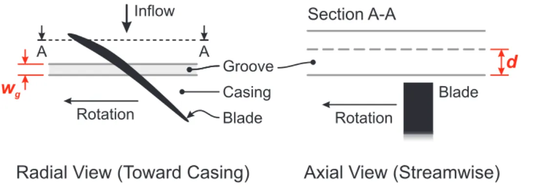
The present work studies a technology called ‘casing treatment’, which can be used to im-prove the stability of a compressor or fan at low flow rates. Casing treatment normally consists of cavities machined into the compressor casing in the vicinity of the rotor blades. There are many different casing treatment designs, but the most common are circumferen-tial grooves and axial slots. These two treatments are explained schematically in Figure1.1. These two treatment designs are well known, but the optimal location, geometry and num-ber of the grooves and slots is not. In the present work, experimental parametric studies are performed to investigate this.
The mechanisms by which casing treatments are able to delay stall in a compressor are also unknown, because the stall inception processes are not completely understood. The present work thus utilises experimental and computational flow studies to investigate the impact of the casing treatments on the compressor flow field in detail.
Casing treatment is often retrofitted to existing compressor designs as a ‘quick fix’ when a stalling problem has occurred. The present work investigates whether including casing treatment at the start of a design process could lead to a more efficient and stable compres-sor, and investigates circumstances in which casing treatments may not be as effective as hoped.
The structure used to present this work is as follows. In Chapter 2, the background to compressor stability problems is introduced, and relevant previously published work is reviewed. Then the experimental and computational methods used throughout the present work are presented inChapters3and 4.
The analysis of casing treatment starts inChapter5, with the performance of a single groove being measured at different axial locations over the blade tips. A detailed experimental and computational study is then performed to link the observed performance of the casing groove to its impact on the compressor flow field at each location.
The geometry of the casing grooves is then investigated further in Chapter 6, where the impact of changing the shape and number of the grooves on the performance of the com-pressor is measured.
Casing slots are investigated in Chapter7, starting with a parametric study to investigate the impact of changing the geometry of the slots on the performance of the compressor. The effect of the slots on the compressor flow field is then investigated, and the flow inside the slots themselves is also studied.
Finally, in Chapter 8, the impact of changes to the compressor’s stall inception pattern on the effectiveness of casing grooves is investigated, and published models are tested to ascertain whether they can predict the observed behaviour. The benefits of designing the compressor blades and casing treatment together, instead of retrofitting the treatment to an existing compressor design, are then investigated.
Circumferential Grooves
Axial Slots
Blade
Radial View (Toward Casing)
Axial View (Streamwise)
Section A-A
Rotation Groove Casing A A Blade Inflow RotationAxial View (Streamwise)
Section B-B
Fin
Land Slot
Rotation
Radial View (
Toward
Casing)
Slot Casing Inflow B B Blade
Background and Literature Review
This chapter reviews the background to the present research. It focuses on concepts rather than detailed comparison of different results, which is saved for later chapters.
The review is divided into four parts. The first part introduces the stability problems en-countered by aircraft engine compressors, and the consequences of unstable operation. The second part introduces the tip leakage flow, which has been linked to the process that leads to unstable operation. This process, called ‘stall inception’, is discussed in part three. In part four, techniques for delaying stall inception (thereby enhancing compressor stability) are reviewed alongside research into their operation. Finally, areas of the literature that require further study are identified and linked to the present work.
2.1
The Unstable Operation of Axial Compressors
Aircraft jet engines must reach maximum efficiency at cruise, to minimise fuel consumption. However, during take off, landing, changes in altitude or other manoeuvres, the engine must operate safely away from this maximum efficiency ‘design point’. This requirement places a particular constraint on the design of the multi-stage axial compressor, which is prone to unstable operation at low flow rates. Unstable operation is unacceptable, so the stable operating range of the compressor should be as large as possible.
The stable operating range of a compressor at a given rotational speed is shown by a ‘char-acteristic’, which is a graph of pressure rise against flow rate. A typical characteristic is shown in Figure 2.1. At high flow rates, the characteristic becomes vertical as the blade rows choke. At low flow rates, the characteristic reaches the ‘stability limit’ and unstable operation occurs. The stable operating range is measured by the ‘stall margin’ between the design point and the stability limit. During design it is important to ensure an adequate stall margin between the maximum efficiency design point and the stability limit. Real multi-stage compressors operate over a range of speeds, so their operating range is shown by a ‘performance map’. A typical performance map is shown in Figure2.2.
Multi-stage compressors are also prone to unstable operation when operating away from their design speed, because the flow rates at either end of the compressor become mis-matched (Cumpsty, 1989a). At rotational speeds lower than the design point value, each stage under-compresses the flow, so the density of the air at the high-pressure (rear) end of the compressor is too low. The Mach numbers of the flow thus increase, causing the rear stages to choke. This limits the mass flow through the compressor at a level lower than the design value, which overloads the blades at the low-pressure (front) end of the compressor due to positive incidence, making them stall. This low-speed stall generally occurs during starting and taxiing. At high shaft speeds, the reverse argument is true and stall is most likely at the rear of the compressor. High-speed stall generally occurs during take off or near the top of the ascent to cruising altitude. If the compressor does stall (at any speed) it becomes unstable and may exhibit ‘rotating stall’ or ‘surge’.
Rotating stall is an instability of the compressor alone. It occurs when the flow becomes non-axisymmetric due to the appearance of one or more ‘stall cells’. Stall cells are regions of reduced (or reversed) axial velocity that rotate around the annulus (Day and Cumpsty, 1978). They divert flow to the rest of the annulus, stabilising the blades away from the stall cell, and creating an annular flow pattern of stalled and unstalled flow. Rotating stall may take the form of part or full-span stall cells, which are shown in Figure2.3. Part-span stall cells usually occur at the blade tips and there is normally more than one around the
annulus. They usually only cover a few blades circumferentially and one or two blade rows axially. These stall cells are normally seen on the high aspect-ratio blades in the front stages of compressors, so part-span stall normally occurs at low shaft speeds (see above). Full-span stall cells cover the whole blade span and there is normally only one cell circumferentially. They usually cover a large proportion of the annulus through the whole length of the compressor. These stall cells are normally seen on the low aspect-ratio blades in the middle and rear stages of the compressor, so full-span stall normally occurs at medium and high shaft speeds. Part-span stall cells will usually merge into full-span cells if the flow rate is reduced so that more than 30% of the annulus area is stalled (Dayet al., 1977). Both types of stall cell move around the annulus at between thirty and eighty percent of the rotor speed, but larger cells tend to rotate more slowly than small ones (Cumpsty and Greitzer,1982;Camp and Day,1998).
Surge is an instability of the whole compression system. It occurs when there is a pres-surised volume (such as a combustion chamber) downstream of the compressor. A surge begins when the compressor stalls and becomes unable to maintain the pressure in the downstream volume (Moore and Greitzer, 1986; Day, 1994; Tryfonidiset al., 1995). The downstream volume thus depressurises through the turbine and compressor. This causes the flow through the compressor to greatly reduce (called ‘classic surge’) or even reverse (called ‘deep surge’) depending on the compressor design (Greitzer, 1976). The reversed flow associated with a deep surge can reach near-sonic speeds in high-speed compressors (Cargill and Freeman, 1991; Day and Freeman, 1994). If the combustor flame is not blown out by the surge, the unloaded compressor may recover, over-pressurise the downstream volume and stall again, causing a ‘surge cycle’ (Day,1994).
Rotating stall and surge are therefore two distinct modes of unstable operation that occur after a compressor stalls (crossing the stability limit is therefore often simply referred to as ‘stall’). Rotating stall can reduce engine thrust and cause over-heating, vibration and wear. These problems are usually worse for full-span stall than part-span stall. Classic and deep surge cycles both cause a periodic loss of thrust. A deep surge can cause severe damage, which may take an engine out of service. Rotating stall or surge can be stopped by shutting down the engine, or reducing the back-pressure on the compressor by decreasing the fuel flow. If a pilot increases the fuel flow to correct for the loss of thrust caused by rotating stall or surge, the load on the compressor will increase. This will make the problem worse, and can turn a part-span stall into a full-span stall or a surge. Stall is therefore dangerous and must not be allowed to occur in aircraft engines.
If a compressor’s tendency to stall cannot be controlled through normal aerodynamic de-sign, stall prevention techniques must be used to move the stability limit to lower flow rates
and increase the stable operating range. These techniques are the focus of this thesis. Later sections will consider the processes that lead to stall and the technologies that can prevent it. However, the tip leakage flow is introduced first, because this is important for both.
2.2
Tip Leakage Flow in Axial Compressors
Compressors have a clearance gap between the rotating blade tips and the stationary cas-ing. There is a pressure difference across the clearance gap caused by the blade’s pres-sure loading, so the ‘tip clearance flow’ leaks through the gap. After the tip clearance flow emerges into the passage on the suction side of the blade, it rolls up to form the ‘tip leakage vortex’. The tip clearance flow and the tip leakage vortex make up the ‘tip leakage flow’. Tip leakage flows are generally detrimental to the stability and efficiency of compressors1 (Peacock, 1982; Freeman, 1985; McDougallet al., 1990; Storer and Cumpsty, 1994;Grafet al.,1998). This work considers the tip leakage flow in low-speed compressors, but many of the concepts are also relevant to high-speed machines (Adamczyket al.,1993; Suder and Celestina, 1996; Chima, 1998; Gerolymos and Vallet,1999). Storer and Cumpsty (1991) andCrooket al.(1993) used computational, experimental and theoretical methods to show that the tip clearance flow is primarily an inviscid phenomenon.
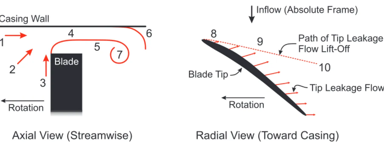
Figure2.4shows the tip leakage flow field pictured byStorer and Cumpsty(1991). The flow entering the tip clearance comes from three areas; the casing boundary layer (label ‘1’), the core flow (‘2’) and the boundary layer being centrifuged up the blade pressure surface (‘3’). On reaching the pressure surface tip corner, the flow separates to form a vena contracta in the tip clearance (‘4’). Compressor blades are normally too thin for the flow to re-attach, so the flow emerges from the clearance as a wall-bounded jet with separated flow near the blade. This emerging flow is not aligned with the core flow so there is a shear layer between the two (‘5’), which generates large losses (Storer and Cumpsty,1994). The tip leakage flow then meets the inflow and separates from the casing (‘6’), before rolling up to form the tip leakage vortex (‘7’).
Chenet al. (1991) and Storer and Cumpsty (1991) present a useful model for considering the tip clearance flow. The model divides the flow into components directed along the blade camber-line (the through-flow component) and normal to the camber-line (the cross-flow component). The through-cross-flow component is linked to the core cross-flow rate, while the cross-flow component is linked to the blade loading. If the cross-flow component of the tip
1Cumpsty(1989a) andGbadeboet al.(2007) report an optimal clearance, but this was smaller than is likely to be sustained in a real machine for mechanical reasons.
clearance flow increases relative to the through-flow component, the clearance flow emerges at a greater angle to the camber line, enlarging the tip leakage vortex and deflecting it further out into the blade passage.
The chord-wise variation in blade loading changes the cross-flow component of the tip clearance flow and the speed and direction at which this flow emerges from the tip clear-ance. Near the leading edge, the blade loading is small, so the cross-flow is also small. The flow emerging from the tip clearance is therefore slow and makes a small angle with the camber-line. This causes the tip leakage vortex to grow slowly (at label ‘8’). As the blade loading increases, the cross-flow increases and the tip leakage vortex grows more quickly (‘9’). As the pressure difference across the tip clearance decreases to the trailing edge, the cross-flow velocities decrease, but the impact on the vortex is small as it is now fully formed (‘10’). Figure2.4 shows that the blade stagger angle, combined with the cross-flow, often causes the tip clearance flow to be axially reversed (McDougallet al., 1990). This will be investigated further in Chapter5.
As stall approaches, the blade loading increases, which strengthens the cross-flow. The tip leakage vortex therefore thickens and swings forward (Yoonet al.,2006), increasing loss and blockage.Furukawaet al.(1999) andWilkeet al.(2005) also suggest that the vortex may ‘burst’ in highly-loaded blading, whileSirakov and Tan(2003) show that the vortex may im-pinge on the pressure surface of the adjacent blade, causing ‘double leakage’. Both of these effects further increase the loss and blockage associated with the vortex as stall approaches. Storer and Cumpsty(1994),Khalidet al.(1999) andSuder(1998) found that tip leakage flow causes most of the loss and blockage in the tip region, andHowardet al.(1994) show that the tip leakage flow can also cause additional losses in downstream blade rows. Hoegeret al.
(2000) show that the blockage caused by the tip leakage flow reduces through-flow veloc-ities near the casing. Greitzeret al. (1979),McDougallet al. (1990),Shabbir and Adamczyk (2005) and others have linked this to stall. The blockage in the rotor and the blade loading will therefore be considered in the present work.
Although cascade studies of tip clearance flow can provide useful information (Cumpsty, 1989a) they must be interpreted carefully because cascades do not have centrifuged blade boundary layers or span-wise blade incidence changes caused by the inlet boundary layer. Casing flow visualisation on cascade endwalls byKang and Hirsch(1994) andSaathoff et al.
(2003) therefore appear different to those conducted on rotor casings bySaathoff et al.and Furukawaet al.(1999). For this reason, the present work uses rotating compressor rigs. Having introduced the tip leakage flow, the next section discusses stall inception.
2.3
Stall Inception
Stall inception is the process of flow breakdown that occurs between stable axisymmetric flow and rotating stall. It can be divided into precursors and the inception itself. Stall inception occurs quickly (usually within a rotor revolution) and in a small area (often only a couple of blades in a whole compressor) so it is difficult to study experimentally. It is an inherently non-linear, stochastic process (Cumpsty, 1989b) and its occurrence is influenced by a range of external factors (e.g. tip clearance, stagger angle, blade erosion and inlet distortion) so it is also difficult to study computationally2. Stall inception is therefore not yet fully understood.
Precursors Stall inception may or may not be preceded by modal precursors, which are circumferentially harmonic velocity variations that rotate around the annulus. Modes grow out of the axisymmetric flow field as the compressor is throttled toward stall and usually extend through the whole compressor (Greitzer and Moore, 1986; McDougallet al., 1990). The harmonic velocity variation increases as stall is approached, so initial detection depends on the sensitivity of the measurement equipment (Camp and Day, 1998). When modal precursors are not present, stall inception suddenly occurs in an otherwise axisymmetric flow field (Day, 1993b). Experimental work byCamp and Day shows that the presence of precursors in a given compressor can be related to the gradient of the characteristic at stall. If the gradient is zero or positive, the compressor will tend to show modal precursors, but if the gradient is negative, the tendency is for no precursors to appear.
Inception Stall inception may be classified as ‘broad inception’ or ‘spike inception’. Broad inception affects several blade passages and directly creates a large stall cell that develops into stall. This inception normally occurs near the blade root, typically moves at the same speed as modal precursors (usually less than 50% of shaft speed) and is thought to be associated with growing three-dimensional separations (Camp and Day,1998). By contrast, spike inception affects a small number of blades (one blade inDeppeet al.,2005) and grows rapidly into a stall cell to cause stall. This inception normally occurs near the blade tip (Day, 1993b) and typically rotates faster (around 70% of shaft speed) than broad inceptions due to its smaller size. In both cases, the new stall cell slows down as it grows into a rotating stall cell (Camp and Day, 1998). The compressors used in the present work tend to stall with spike inception so this is considered further below.
2Simulations of stall inception are often compromised by stall inception being caused by numerical errors rather than flow physics.
Spike Inception The small size of spikes and the speed at which they move and grow makes them hard to study experimentally. There is therefore disagreement about what causes spikes and what they actually look like. Deppeet al. (2005) suggests that spikes are caused by tip leakage flow being suddenly pushed forward by axially reversed flow near the trailing edge. The computational results in Hoyinget al. (1999) and Luet al. (2006b) blame the tip leakage vortex spilling around the front of the neighbouring blade’s leading edge and stalling it. Yoonet al. (2006) and Seitz (1999) explicitly disagree with Hoying’s analysis, and Seitz blames the interaction of the tip leakage vortex with the core flow in the passage between the blades. Vo(2001), a co-author of Hoying, implicates both forward spillage of the tip leakage vortex and axially reversed flow occurring around the blade trailing edge. The underlying mechanisms of spike generation and their development into rotating stall cells are therefore not well understood. Numerical work by Gourdainet al.
(2006) and Inoueet al. (2000) have predicted the flow field at the early stages of rotating stall, but these have yet to be verified experimentally. This subject will be revisited later in the present work.
A Compressor’s Route into Stall Camp and Day(1998) show that the precursors can be related to the type of stall inception. If modal precursors are not present before stall, spike stall inception usually occurs. However, if modal precursors are present, they reduce the inflow velocity to a large number of blades simultaneously, which can lead to either broad or spike inception. Even in a given compressor the stall inception type is not necessarily constant and can be changed by altering the inflow (Simpson and Longley, 2007), shaft speed (Dayet al.,1999) or geometry (Dobrzynskiet al.,2007). The stall inception mechanism will therefore be checked for each new set of tests in the present work. Either or both inception types may occur in multi-stage compressors, but Day and Freeman (1994), Day (1994) andWilson and Freeman (1994) report that the stall inception processes are similar in both high and low speed machines.
Predicting Stall The lack of understanding surrounding the mechanisms of stall inception (and their complexity) makes accurate prediction of the stall point difficult. Most methods involve some kind of diffuser analysis with corrections (Cumpsty, 1989a). Greitzeret al.
(1979) compares loading on the rotor blades and the casing wall, and predicts stall when the loading on either reaches a critical level. However, this ignores the impact of the stator and the aspect ratio, which can both affect stability (Cumpsty, 1989a). Koch(1981) applies a straight diffuser approach to compressors using empirical correlations averaged over the whole stage at the mean radius. This simple approach gives a remarkably good indication of the stall point. Smith(2002) reviews some related methods. Camp and Day(1998) suggest
that there is a critical incidence (or tip loading) at which the compressor stalls. However, none of these methods give really good predictions. The stall point will also change during service because of external factors such as blade erosion due to foreign body ingestion or tip rubbing (CAA,2004), the effects of rain or ice ingestion (NTSB,1977;Day et al.,2008) or enlarged tip clearances caused by differential expansion of the casing and blades, adding further complication. Predicting the stall inception type is equally difficult and will be discussed in more detail in Chapter8.
2.4
Stability Enhancement Methods
To prevent stall in a compressor, stall inception must either be delayed or eradicated before it can grow into a rotating stall cell. The desired outcome is to improve the stall margin (stable operating range) without affecting the design point, as shown in Figure2.5. This can be achieved using active or passive control techniques.
Active control methods use a feedback control system and actuators to modify the compres-sor flow. Problems with active control include mechanical and electrical complexity in the control and actuation systems and, in some cases, a need for thermodynamically expensive pressurised air. Passive control methods use localised changes to the compressor geometry to control stall with no external input of any kind. Problems with passive control include complex manufacture and reduced efficiency and mechanical integrity. While both types of system are potentially expensive, passive methods are simpler, lighter and safer due to the lack of a control system. The present work considers passive methods, but some relevant findings from flow studies considering active methods will be reviewed first.
2.4.1 Active Control Methods
Flow control techniques such as bleed valves and variable-stagger blade rows are commonly used to start multi-stage compressors and cater for off-design operation. Bleed valves re-move air from the compressor to increase the flow through the front stages and prevent stall at low rotational speeds (see Section2.1), while variable blade rows reduce the incidence changes associated with off-design operation (Paduanoet al.,1993). Both systems are heavy, bulky and expensive, so they cannot be applied throughout the whole compressor and do not cure all stall problems. Recent research has therefore focused on more precise active control methods that suppress stall by injecting or bleeding small quantities of air in or out of the compressor.
Injected air is normally aimed at the tip clearance to prevent spike stall. Suderet al.(2001) found that injectors should maximise the mass-averaged axial velocity close to the casing wall to re-invigorate the casing boundary layer and reduce the incidence (and loading) on the blade tip. Suderet al.use this technique to stop fully-developed rotating stall and even replace variable inlet guide vanes (albeit inefficiently). Cumpsty (1989b) agrees that casing boundary layers are important in stall inception. Deppeet al. (2005) varied the angle of injection about a radial axis and found that the best injection angles were between axial and -60◦, against the rotor motion. Traverses showed that this increased the through-flow in the tip region. Therefore, bothSuderet al. and Deppeet al. suggest that increasing the tip clearance through-flow and decreasing the cross-flow improve stability. Suderet al. (2001) also show that the compressor stalls with injection when the loading at the tip reaches the same level that caused stall without injection, which agrees with the critical incidence model ofCamp and Day(1998).
Beheshtiet al. (2006) injected air axially into the tip clearance via a wide circumferential groove (or trench) over the blade tips. The best results were gained when the flow was injected at high velocity along the camber line (in the relative frame). Baeet al.(2005) found that stream-wise air injection in the tip clearance was more effective than using oscillating jets to break up the flow. These papers agree with injector design work by Strazisaret al.
(2004), which concludes that the optimum geometry provides high axial velocities into the tip clearance very close to the casing wall (using the Coanda effect). All these authors agree with Suderet al. (2001) that maximizing injected velocity is the key to stability enhance-ment. Other work on injection byScheidler and Fottner (2003) shows that active control of air injection can cure stability problems associated with inlet distortion and significantly increase the pressure rise across a transonic compressor, although Scheidler and Fottner (2006) found that active stabilisation was less effective at low speeds.
This injection work shows that stability can be enhanced by injecting flow into the casing boundary layer just upstream of the blade row, or into the tip clearance itself. The key factor is that the flow must have a high velocity. The literature advises that the jet direction should be chosen to unload the tip (Suderet al.,2001;Strazisaret al.,2004) or follow the camber-line in the relative frame (Beheshtiet al.,2006). The effect of both of these viewpoints on the tip clearance flow as modelled byChen et al.(1991) andStorer and Cumpsty(1991) is the same. The through-flow is augmented and the cross-flow is diminished. Reducing tip clearance cross-flow relative to tip clearance through-flow should therefore improve stability. This can be done by interrupting the cross-flow or augmenting the through-flow. This idea will be considered throughout the present work.
is needed to activate injection only when needed. This is complex because different ap-proaches are required for different stall inception behaviours. Day(1993a) shows that pre-cursor modes can be suppressed with a circumferentially-harmonic valve response, while spikes and small stall cells can be eradicated using a local valve response. Freemanet al.
(1998) andFfowcs Williamset al.(1993) extended this to engine compressors, and show that surge cycles can be stopped by preventing the stall that occurs prior to the surge. It would appear that modal precursors are much easier to target than spikes because they build up slowly and can be suppressed by a simple harmonic response. However, engine control sys-tems must be able to handle a large range of stalling mechanisms because these can change during service (Dayet al., 1999). In some cases, complex signal analysis has been used to remove the need for a priori knowledge of the stall inception mechanism (Paduanoet al., 1993; Weiglet al., 1998; Hösset al., 2000; Leinhoset al., 2002; Scheidler and Fottner, 2006; Christensenet al.,2008) but despite this work, active control has not found widespread use.
2.4.2 Passive Control Methods
The most common passive method for stall control is some form of endwall treatment, either hub treatment (for cantilevered stators) or casing treatment (for rotors). Casing treatment is the most commonly used and has existed since the 1950s (Wilde,1953). Hathaway(2007) reviews a variety of different casing treatments, but most are either groove or slot-based. Early forms of these treatments proposed by Osbornet al. (1971) and Mooreet al. (1971) are shown in Figure2.6. Groove-based treatments typically generate smaller stall margin improvements than the slot-based treatments, but usually cause smaller efficiency losses (Bailey,1972;Fujita and Takata,1984).Greitzeret al.(1979) suggested that casing treatment is only effective if stall inception occurs near the casing. This is investigated in Chapter8.
Groove-Based Casing Treatments
Groove-based casing treatments usually consist of one or more circumferentially continuous grooves cut into the endwall above the rotor tips (see Figure 2.6). They provide better efficiency and mechanical integrity than casing slots, and although they generate a smaller stall margin, this may be all that a designer requires (e.g. to correct stage mis-matching). Designing a grooved casing treatment is currently difficult because the interaction of the grooves with the flow field and stall inception processes are not fully understood. This leads to disagreement in the literature about how grooves work and where they should be located. Shabbir and Adamczyk(2005) used computational methods to show that near
the casing of a smooth-walled rotor, the net axial pressure force is balanced by the axial wall shear stress. They suggested that casing grooves can generate an additional axial force by transporting axial momentum radially, thereby increasing the net axial pressure force that the near-casing flow can tolerate, improving stability. The grooves near the leading edge generated this axial force more effectively, so it was concluded that these generate the greatest stability improvement. Computational work byVoet al.(2008) suggested two crite-ria that must be met for stall to occur. The tip leakage flow must ‘spill’ around the leading edge of the adjacent blade and there must be axially reversed flow moving forward from the trailing edge. Luet al.(2006b) andMülleret al.(2007) showed that grooves can deflect the tip leakage vortex downstream by manipulating the tip leakage flow. Grooves near the leading edge deflect the vortex most, so these authors suggest that such grooves stabilise the compressor most effectively by preventing forward spillage. Princeet al. (1974) suggested that casing grooves work by moving blade loading aft. By contrast, the experimental work by Bailey (1972) concluded that the optimum groove location is near mid-chord, not the leading edge. The literature does not fit together well, so the location of grooves and their interaction with the near-casing flow will be studied in detail in Chapter5.
Fujita and Takata (1984) found that using multiple grooves increases stall margin but re-duces efficiency, while Bailey (1972) found that deeper grooves were more effective than shallower grooves. Rounding off the grooves (Barnettet al.,2003) or installing baffles within them (Princeet al.,1974;Fujita and Takata,1984) have also been investigated, but these stud-ies did not consider the axial location of the grooves (and the rounding work was done on an inclined groove). Because these results are confusing, multiple grooves and different groove geometries will be tested in Chapter6.
Slot-Based Casing Treatments
Slot-based casing treatments usually consist of a number of circumferentially discrete slots cut into the endwall above the rotor tips, which may extend axially upstream of the rotor. Although they reduce efficiency more than casing grooves, are less robust and do not work well with abradable casing linings, they can provide a large stall margin improvements. The early NASA geometries (see Figure2.6) had slots located entirely over the blade tips. This design generates large stability enhancements, but reduces the design point efficiency. Experimental flow studies byPrinceet al.(1974),Smith and Cumpsty(1984) andSeitz(1999) show that there is significant recirculation through the slots caused by the rotor pressure rise. Smith and Cumpstytentatively conclude that this recirculation stabilises the compres-sor by interrupting the tip leakage flow and removing blockage from near the casing. They
also suggest that unsteady effects within the slots can be disregarded. Unfortunately, the large recirculation through the slots (up to 10% of the mass inflow at stall according to Seitz, 1999) wastes pressurised air and leads to mixing losses, both of which cause unac-ceptable efficiency reductions of around 2%. However,Princeet al.(1974) found that adding circumferential baffles across the axial slots (to prevent recirculation) reduced the efficiency penalty with only a slight reduction in stability improvement. This suggests that steady recirculation is not the only mechanism and unsteady effects may also be important. Waterman(1992) and Seitz(1999) developed the over-blade NASA geometry by moving it forward so that the greater part of the slots is upstream of the blades rather than over them. Seitz used a parametric study to set the extent of the slot from 75%cx,r upstream of the leading edge to 25%cx,rdownstream, and also set the skew angle to 60◦. This maintains the stability improvement, but reduces the efficiency penalty by a factor of four. Luet al.(2009) made similar findings. The present work will expand these studies.
Seitz (1999) found that the reduction in efficiency loss with forward positioned slots is caused by the decrease in driving pressure force (caused by the decreased rotor overlap) reducing the recirculation through the slot to only 1% of the overall compressor mass flow at stall.Seitzalso finds that the slots in the forward position have a smaller impact on the near-casing flow and blockage compared with the over-blade geometries (again suggesting that blockage and stall are not directly linked). However, the mesh resolution in the CFD used bySeitz was quite low and the blockage at very low flow-rates was not investigated. The present work will study the near-casing flow and outflow blockage further. This reduction in recirculated flow rate relative to the over-blade treatments adds weight to the results of Princeet al. (1974), who suggested that steady recirculation is not the only mechanism behind the performance of casing slots, but this is contradicted byNing and Xu(2008) who successfully used a steady CFD analysis to model the impact of slots.
Wilke and Kau (2004) show that the flow inside forward slots applied to a high-speed machine is very similar to that observed by Seitz (1999) and Luet al. (2009), despite the differences in casing static pressure field between transonic and subsonic compressors. Wilke and Kaualso round off the rear of the slots to guide the recirculating flow smoothly through them (suggested for the over-blade treatment bySmith and Cumpsty,1984). They conclude that the treatment works by weakening the tip clearance flow near the leading edge. The treatment works well, suggesting that recirculation is more important than un-steady effects in this case. However,Wilkeet al. (2005) find that forward slots do not work so well with contoured endwalls, which could be a problem in transonic fans.
Lee and Greitzer(1990) andSeitz(1999) both used steady suction and blowing through slots to further understand the operation of both over-blade and forward slots. Suction from slots
extending from the leading edge to 25% chord, and blowing from the leading edge to 25% chord upstream, were both found to improve stability. Both authors found that constant suction and/or blowing improved stability less than the full casing treatment, although this may have been caused by the flows not correctly mimicking the treatment aerodynamics. However, both authors also found that the slots extending aft from the leading edge to 25% chord increased stability by 7% without blowing or bleeding (as found byKoch,1970). This result leadsSeitz to conclude that simple recirculation does not completely explain casing treatment behaviour, and unsteadiness should be considered. The role of unsteadiness is therefore unclear and will be investigated in Chapter7.
Recirculating Casing Treatments
Recirculating treatments take air from one point in the compressor and return it at another, generally without any active control. The treatment studied byAzimianet al.(1990) bleeds flow from near the blade leading edge and feeds it back into the flow upstream after having been turned by vanes. The authors conclude that steady recirculation is the key to stability enhancement. Hathaway (2002) bleeds and then re-injects flow at many different axial locations and finds that in a transonic machine, the best place to bleed is just at the exit to the rotor, while the best place to inject is just in front of the point of greatest tip clearance flow. These locations are similar to the areas covered by the over-blade slots, but unlike the slots, the recirculating treatment did not reduce efficiency. Hathaway concludes that the good efficiency was caused by the removal of casing endwall blockage compensating for the losses in the treatment (made possible by careful injector design) and reduced mass flow through the treatment (made possible by using high injection velocities).
These results show that introducing high velocity flow into the tip clearance region is benefi-cial for stability, and that introducing loss in a casing treatment is acceptable if the treatment causes greater loss reductions in the blade row. The effectiveness of the Hathaway treatment also shows that simple rules of thumb are not sufficient for robust design. The effect of the treatment on the compressor flow field must be understood.
2.5
Discussion
The fundamentals of stall inception are not yet fully understood, so designing a casing treatment to precisely target inception phenomena is not currently possible. Understand-ing the stall inception process is an ongoUnderstand-ing task. However, the literature provides many interesting observations which will be advanced in the present work.
The literature is divided on where circumferential grooves should be placed for best perfor-mance. The optimum location and number of casing grooves will therefore be investigated in detail. Different groove cross-sections and configurations will also be studied to find the best geometries. Past work on casing slots has defined the best choice for some of the slot dimensions. This work will extend this to cover all the dimensions of casing slots. The parametric results will be linked to detailed experimental and computational studies of the flow fields in order to improve design guidance and understanding.
Manipulating the tip clearance flow so as to enhance through-flow and reduce cross-flow in the tip clearance appears to increase stability. This decreases losses generated by the shear layer between the emerging tip clearance and core flows and deflects the tip leakage vortex back into the blade passage. This in turn reduces the size of (and therefore blockage caused by) the tip leakage vortex. These effects decrease the losses caused by the tip leakage flow and improve the passage through-flow in the tip region, which together improve efficiency and reduce the blade loading. The processes used to manipulate the tip clearance flow must target the flow very close to the casing to be effective. The present work will therefore investigate the impact of casing treatments on the outflow blockage, blade loading and near-casing flow fields.
The methods used to manipulate the tip clearance flow may themselves introduce additional losses. Therefore, to maintain efficiency at the design point, the casing treatment must either reduce losses in the blade row or handle such a small flow rate that the loss inside the treatment is negligible. The overall impact of casing treatments on efficiency will be analysed in this work.
Casing slots have been shown to contain both steady recirculation and unsteady effects. The literature is divided on the relative importance of these for providing increased stall margin. The importance of unsteady effects will therefore be investigated in the present work, using detailed experimental and computational methods to develop understanding and design guidance.
Greitzeret al. (1979) suggests that there is a limit to the effectiveness of casing treatment, caused when the location of stall inception changes. The present work will therefore check
for changes to the stall inception mechanism throughout. Later work in the 1990s intro-duced modal and spike stall inception and improved our understanding of the mechanisms of stall. This work will therefore investigate how changes to the stall inception mechanism may alter casing treatment performance.
The geometric complexity of casing treatments must to be traded off against performance. For example, the complex ducting in recirculating treatments greatly increases manufactur-ing costs and this must be justified. The present work therefore compares the performance of casing slots with less complex casing grooves to enable design choices to be made. In summary, based on this literature review, the present work will investigate the optimum axial location and geometry for single and multiple casing grooves. The optimum geometry for casing slots will also be investigated by adding to existing work. The impact of casing grooves and slots on the near-casing flow, blade loading, blockage, stall inception mecha-nism and efficiency will be studied. The significance of unsteady effects inside casing slots will also be quantified. Finally, the impact of the stall inception mechanism on casing treat-ment performance and the advantages of combining blade and treattreat-ment design will be considered.
Flow Rate
Choke Stability Limit
PressureRise
Design Point
Figure 2.1: A schematic constant speed characteristic for a high-speed multi-stage axial compressor showing choke, the design point and the stability limit.
Flow Rate
100% 80% 60% 40% 88% 86% 84% 82% Constant Efficiency Contours Constant Speed Characteristics Choke Stability LimitPressureRise
Figure 2.2: A schematic performance map for an axial compressor showing choke, the stability limit, characteristics at different rotational speeds and contours of efficiency.
Surge Full-Span Stall
Part-Span Stall
Reduced or reversed axial velocity
Figure 2.3: An axial cut showing the layout of part and full-span stall cells and surge.
Rotation Casing Wall
3
2
1
4
5
6
7
8
9
Path of Tip LeakageFlow Lift-Off
Tip Leakage Flow
Blade
Radial View (Toward Casing)
Axial View (Streamwise)
Blade Tip
Inflow (Absolute Frame)
Rotation
10
Figure 2.4: Two views of a typical tip leakage flow field in an axial compressor (shown in the relative frame of reference).
Flow Rate
PressureRise
Stall Margin Improvement
Stall Point With Casing Treatment
Design Point
Stall Margin
Normal Stall Point
Normal Compressor
Compressor with Casing Treatment
Figure 2.5: Constant speed characteristics showing a stability enhancement technique (cas-ing treatment) mov(cas-ing the stall point to a lower flow rate without chang(cas-ing the design point. These characteristics are from the Natal compressor (see Chapter3). Since this is a low speed compressor, the low speed definition of stall margin is shown.
Casing Grooves Casing Slots
Early Casing Treatments From Osbornet al(1971)
Experimental Methods
This chapter describes the experimental methods that were used to quantify the perfor-mance of different casing treatments, investigate the compressor flow field and calibrate computational fluid dynamics (CFD) models. The chapter is divided into four parts. The first part introduces the compressors from which the data was gathered. The second part presents the measuring equipment that was used and its capabilities. The third part describes the different experimental and measuring techniques that were used. The fourth part contains the results of an initial study to check that the stalling behaviour of the com-pressors is unaffected by Reynolds number.
3.1
The Compressors
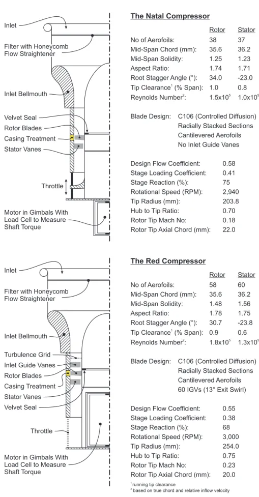
The two compressors used for the present experimental work were axial-flow, low-speed, single-stage, vertical-axis machines located at the Whittle Laboratory. The ‘Natal’ and ‘Red’ compressors are both models of subsonic stages in an aero-engine compressor. Figure3.1 shows partial cross-sections of both compressors, with selected design parameters. Their design is discussed in more detail below.
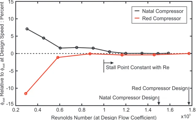
Inlet and Flow Conditioning Air enters through an inlet at the top of the compressors. It then passes through a honeycomb flow straightener, a plenum and an inlet contraction to reduce large disturbances in the flow. The air then enters the parallel working section, where there is further flow conditioning. This consists of boundary layer trips to give realis-tic boundary layers and (in the Red compressor) a turbulence grid to generate the required turbulence levels. In the Red compressor, the turbulence grid generates a free-stream tur-bulence intensity of 2.5% at the rotor inflow. The Natal compressor is run in a closed room, so the rotor inflow turbulence level is 2.2% without a turbulence grid. These values of tur-bulence intensity are lower than the 4 to 6% found in embedded multi-stage rotor inflows (Camp and Shin,1995;Cumpsty,1989a), butSchlichting and Das(1969) show that they are sufficient to cause transition at the leading edge of the rotor blades outboard of mid-span. The blade roughness, noise and vibration will also encourage transition. Experiments were also performed to show that both compressors were operating at Reynolds numbers greater than those at which viscous effects such as laminar boundary layer separation affect the stalling behaviour and overall compressor performance (see Section3.4).
Working Section The working section in the Red compressor contains rows of inlet guide vanes (IGVs), rotor blades and stator vanes. The IGV and rotor blade rows are axially spaced by 130%cx,r at the casing, and the rotor and stator rows are spaced by 140%cx,r. The working section in the Natal compressor contains rows of rotor blades and stator vanes spaced by 125%cx,r (no IGVs). The large rotor-stator gaps reduce the coupling between the stator and rotor, reducing the complexity of the results. In both compressors, the stator vanes are cantilevered from the casing, so the hub adjacent to the vane tips rotates with the rotor. The tip clearances are shown in Figure3.1. On both compressors, the casing is made of stacked rings that can be changed to install casing treatments (see Figure3.1).
Both compressors have controlled diffusion blading designed by Rolls-Royce for the C106 compressor. The Red compressor has the same geometry as the C106 compressor, so the blades fit perfectly. The span and hub-to-tip ratio of the Natal and C106 compressors are similar, but the radius of the Natal compressor is smaller than the C106. The blades are thus
slightly under-twisted, but the incidence mis-match is small (less than 1◦). To fit the Natal compressor, the C106 blades and vanes were shortened by 1.7 mm and re-staggered to give the correct mid-span incidence (using velocity triangles). Small gaps at the rotor and stator roots were then filled with silicone sealant to prevent leakage flow.
Exhaust Downstream of the working sections there is a settling length to decouple the working section from the throttle. The throttle in the Natal compressor is a flat plate, orthogonal to the compressor axis, which is moved up and down by a gear system to control the flow rate. The throttle in the Red compressor consists of two close-fitting annular sheets of metal containing three identical apertures, which are moved relative to each other (like shutters) to control the flow.
3.2
Measurement Equipment
This section describes the equipment used to measure, record and process data.
3.2.1 Pressure Measurements
In the present work, ‘steady’ pressures are those that vary with frequencies much lower than the shaft speed. Steady pressures were used to measure the compressor performance and the output from pneumatic traverse probes. By contrast, unsteady pressures vary with frequencies similar to the blade passing frequency. Unsteady pressures were used to mea-sure stall inception and the blade-to-blade casing static presmea-sure field.
Steady pressures were measured with Honeywell 1 psi pressure transducers (using plastic tubing for connections to tappings or probes). These were periodically re-calibrated using the same Furness Controls micromanometer with a range of 0-1.9 kPa. The transducer zero offset was recorded before every run and subtracted from the data before the calibration was applied (once the compressor and logging system was warmed up, zero-level drift was less than±2 Pa). The combined error in pressure measurement (including zero level drift, calibration and quantisation errors) was±3 Pa, or±0.4% of a typical inflow dynamic head. Unsteady pressures were measured with Kulite 5 psi high-frequency pressure transducers. The 1.5 mm diameter transducers were covered with a perforated screen and mounted flush with the casing wall. They were calibrated using the same Furness Controls micromanome-ter. The transducer zero offset was recorded before every run and subtracted from the data
before the calibration was applied. The output from the transducers was logged at 60 kHz and filtered at 30 kHz (well below the resonant frequency of 150 kHz) giving 20 and 30 data points per blade passage in the Red and Natal compressors respectively. The time-averaged pressures measured by the high-frequency transducers were subject to temperature drift, so when this data was required (e.g. for blade-to-blade measurements) the steady-state pres-sure was meapres-sured (as above) and combined with the unsteady prespres-sure data.
3.2.2 Unsteady Velocity Measurements
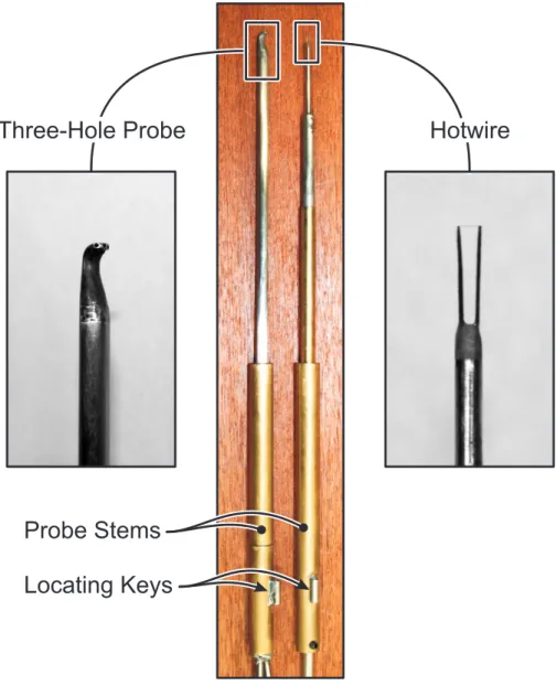
Unsteady velocity measurements were used for recording turbulence parameters and blade-to-blade flow angle and velocity. A single element, normal, hotwire probe was used. This was yawed (rotated about the probe stem) to obtain measurements from which flow angles could be calculated (see Section 3.3). The hotwire was calibrated at the start and end of each day’s testing using a steady-flow wind tunnel and the data was fitted to a fourth order polynomial (Jorgensen,2005). The uncertainty in the velocity measurements due to the cal-ibration drift was less than±3% of typical free-stream values. The Bearman correction was always used to correct the hotwire output for changes in atmospheric temperature. The out-put from the hotwire was logged at 100 kHz and filtered at 30 kHz to avoid aliasing, giving 35 and 50 data points per blade passage in the Red and Natal compressors respectively.
3.2.3 Shaft Torque and Speed
These measurements were used for calculating the input power and blade speed. The motors driving both compressors were mounted in a freely-rotating gimballed frame so that the torque reaction acted against a load cell. This was calibrated before each set of experiments using dead weights attached to a torque arm. The zero offset was recorded before every run and subtracted from the data before the calibration was applied. The zero-level drift, measured before and after each experiment, was never more than ±0.5% of the torque at full load. The torque calibration measurements never varied by more than
±0.5%. Rotational speed was measured using a light-gate on the rotor and processed using a trigger box, which also provided the shaft angle trigger for data logging.
3.2.4 Atmospheric Conditions
The atmospheric temperature was measured using a mercury thermometer near the com-pressors. The atmospheric pressure was measured using a standard mercury barometer.
3.2.5 Data Acquisition and Analysis
Data was acquired using a National Instruments data acquisition card with a 16-bit resolu-tion. This high resolution made the voltage quantisation levels small (0.15 mV for a typical 0-10 V measurement range). Sixteen sequential logging channels were available, sharing a maximum logging frequency of 1.2 MHz (i.e. one channel could be logged at 1.2 MHz, 10 channels could be logged at 120 kHz etc). The logging system was controlled by Lab-View. This controlled the data acquisition, wrote the raw data to files (for later processing), performed real-time data analysis (to monitor the experiments) and controlled the stepper motors (to move probes). The data was then processed using Matlab and Tecplot.
3.3
Experimental Techniques
This section describes the techniques used to record the experimental measurements.
3.3.1 Performance Characteristics
The flow coefficient (φ) is based on the average velocity of the inlet flow, which was found by calibrating the inlet. The stagnation pressure of the inlet flow was measured using pitot tubes. There were four pneumatically averaged pitot tubes in the Red compressor inlet and one in the Natal compressor. The stagnation pressure was corrected, using a loss coefficient, to give the average value downstream of the inlet. The loss coefficient was found using three-hole probe traverses downstream of the inlet, and was averaged over the compressor flow range. The static pressure was measured using casing tappings downstream of the contraction. There were eight pneumatically averaged tappings in the Red compressor inlet and four in the Natal compressor. The static pressure was corrected in the same manner as the stagnation pressure. The axial velocity and flow coefficient were calculated from the corrected pressures. The uncorrected axial velocity measurement error was±0.3% at the design point, but the use of corrections reduced the absolute accuracy of these measurements to±1.5% (due to inaccuracies from the traverse data). The repeatability between builds was better than±0.15% (verified by repeated experiments).
The total-to-static pressure rise coefficient (ψ) is based on the stagnation pressure of the rotor inflow and the static pressure at the casing of the stator outflow. The rotor inflow stagnation pressure was gained from the stagnation pressure measured with the inlet pitot tubes by using corrections based on loss coefficients (as described above) to give the average
stagnation pressure at the rotor inflow (i.e. downstream of the turbulence grid and IGVs in the Red compressor). The outflow static pressure was measured downstream of the stator by eight pneumatically averaged casing tappings in the Red compressor and four in the Natal compressor. The measurement error was±0.8% at the design point, reduced to
±1.2% by the correction inaccuracy. Repeatability between builds was ±0.5% (verified by repeated experiments).
To measure the characteristics, data was logged in sequential periods of 0.1 s at 100 kHz and each period was averaged to form a point on the characteristic. The compressor was throt-tled slowly (design point to stall taking two minutes) so that the operation of the compressor was quasi-steady. Compared to measuring discrete operating points, this continuous log-ging process is faster, allows more accurate measurement of the stall point and records any kinks or steps in the characteristics.
When the efficiency (η) was required, the shaft torque was also measured. The contin-uous logging process was still used, but the measurements were averaged over a longer period (0.4 and 0.5 s in the Red and Natal compressors respectively) to reduce the impact of drive system resonances. The compressor was thus throttled at a slower rate to ensure quasi-steady operation (design point to stall taking five minutes). The efficiency was cal-culated from the shaft torque and static pressure rise over the rotor and stator as shown in Equation 3.1. The static-to-static pressure rise can be used because both compressors have repeating, incompressible stages. Repeated experiments showed that the efficiency was repeatable within±0.1% provided the compressor was warmed up properly, electrical interference was monitored, and the air was steady and at a roughly constant temperature.
η= m˙∆Po
ρ(ωτ) =
˙ m∆Ps
ρ(ωτ) (for a repeating, incompressible stage) (3.1)
Total-to-static pressure rise and efficiency characteristics of the Red and Natal compressors are shown in Figure3.2. Data is included for each compressor fitted with a smooth and treated casing wall for reference (see Chapters7and8).
3.3.2 Parametric Tests
Parametric tests are used throughout this work to measure the relative performance of different casing treatments. In all these tests, two characteristics were measured with a smooth casing wall, then three with a treated casing wall, then another two with the smooth wall again. If the stalling flow coefficient or maximum efficiency of the four smooth wall,
or three treated wall, characteristics disagreed by more than the accuracies quoted below, the entire dataset was re-taken. This technique allowed the stall margin improvement (SMI) and pressure rise improvement (PRI) to be measured within 0.5% and the design point flow improvement (DPFI) and maximum efficiency improvement (MEI) to be measured within 0.1%. Once the compressor and logging system was properly warmed up, however, discarding a set of data was rarely necessary.
In Chapters 5, 6 and 8, various casing groove designs are tested at different axial loca-tions. This was achieved, without changing the rotor-stator spacing, by placing circular shims (i.e. very thin casing rings) under the treated casings. This did not change compres-sor performance, but the differential testing outlined above was maintained for each shim configuration.
3.3.3 Pneumatic and Hotwire Probe Traverses
This section discusses the traverse gear, probes and techniques used to record traverse data.
The Traverse Gear
The same probes and traverse gear were used on both compressors. The traverse gear had three degrees of freedom that were all driven by computer-controlled stepper-motors. The probes were fixed in a yawing mount with a resolution of 0.3◦ per step. This was mounted on X and Y linear tables with resolutions of 6.5µm per step. The whole traverse gear could be moved axially (using sliding mountings) to allow access at any axial location.
The probe was inserted into the flow through a slot in the casing, which was lined with foam to prevent leakage. If the traverse slot was not in use, the foam lining was removed and the slot was blanked off. The probes themselves were located in the yawing mount by a key on the probe stem (see Figure3.3). The probes were nulled to the accuracy of the yaw traverse gear before every set of experiments using a small calibration tube attached to an industrial vacuum cleaner. The radial probe location was set by lightly touching the hub with the probe and then withdrawing it so the closest measurement point was 0.8 mm (1.3% span) away from the hub wall. Home switches on the traverse gear were used to re-set the probe before each subsequent traverse.
During traverses, the probe was moved radially from the hub to the casing. When the probe yaw angle was changed (see below), the controlling software and stepper motors automatically corrected any corresponding changes to the lateral location of the probe head.