1
CHAPTER 1
INTRODUCTION
1.1 IntroductionHigh demand of the usage of public transportations leads to many companies built to satisfy the demands. One of the famous and demanding public transportation is the express buses. This public transportation commonly is a big help when someone is travelling far away alone. Some passengers find it more convenient travelling with the express buses rather than driving alone that leads to so many possibilities of incidents such as dozing off while driving and car crashes.
Some passengers who travel with express buses that take a long time to reach the destination often overslept and miss their destination. This is due to the current system of tracking passengers only caters the part of boarding and not the part where passengers have to get off at their destination. As the consequence of this situation, they might have to consume more money and time to go back to the intended destination and it is not very convenient.
This project intends to helps ease the process of travelling with express buses starting from the purchasing of tickets until the tracking of passengers boarding and getting off from the bus. The technology of QR-code will be used in developing this project as to implement the recent technology used and of course it is widely used and easy to implement.
2 1.2 Problem Statement
Problem statement is the description of problems that arise currently and needed to be solved by the end of the project testing and evaluation. The problems arises that resulted to this project are:
• Passengers might overslept and miss their destination, lost time and money, miss class-student scope.
• Passengers have to go to the ticket counter to purchase tickets and it is not very convenient as it takes much time and effort.
• Passengers might lose the printed tickets purchased from the counter.
• Traditional method of tracking passengers on board only done manually, it does not cover the part where passengers get off the bus.
1.3 Objectives
The main goal of this project is to produce an application that can help ease the process of purchasing tickets and tracking the boarding and getting off of the passengers from the bus. Therefore, the objectives to reach the goal are as follows:
• To design suitable interfaces and frameworks to produce integrated e-ticketing and also to track passengers who board and get off the bus.
• To develop an Android application that supports express bus integrated e-ticketing and also can track passengers who board and get down from the bus on each trip. • To evaluate the application proposed in solving passengers boarding and drivers
3 1.4 Project Scopes
Project scopes often help in determining the focus of a project and making the development more organized and systematic. For this project, the scopes are divided into two parts that are user and system. For user scope, there are Driver and Passenger. The system scope of this project is basically what each user can do when using this project. The details will be shown below:
1. Drivers:
View route details Track passengers 2. Passengers:
User registration Check trip
Buying e-tickets with QR-code
1.5 Limitation of Work
This system has a few limitations of work, which are:
Implementation of QR-code requires usage of smartphones No GPS usage for detecting location of driver/ passengers
4 1.6 Thesis Structure
This thesis consists of 4 chapters. The first chapter, which is Introduction, explains briefly about Bus Passenger Tracker App which includes the project background, problem statements, objectives, scopes of this project and limitation of work. The second chapter, Literature Review, consists of summaries of readings and researches of recent project related to this project such as attendance system and the usage of QR-code in solving problems. Next, the chapter of Methodology discusses the techniques used in developing this project. This chapter will also covers the Gantt chart, system requirements and system designs. The system designs consist of another four subtopics which are Frameworks, Process Model, Data Model and Interface Design. The Process Model includes the Context Diagram, Data Flow Diagram and flowcharts of the system. In Data Model, there are Entity Relationship Diagram and database scheme. Lastly, Chapter 4 will conclude the overall thesis and produce conclusion.
5
CHAPTER 2
LITERATURE REVIEW
2.1 IntroductionLiterature Review discusses the researches and analysis of already existing systems and implementation of possible techniques and method to use in this project. This is done to help determine the best possible techniques and methods so that the feasibility of the project can be determined. In this project, the topics related are the attendance system, QR-code implementation in academic problems and e-ticketing. As these topics related closely and solely in this project, the researchers are made as to make it references to develop the Bus Passenger Tracker App.
2.2 Project and Research
2.2.1 Analysis on attendance system using Android and mobile phones
Automated Attendance Monitoring System using Android Platform: This paper proposes that the attendance of students to lectures is taken through Android platform. The advantages that I found are students get to mark their attendance with a single click, lecturers can generate report on a single click and faculty members get to track student’s record. On the contrary, the disadvantage is that students can falsify their attendance since there is no location detection on their mobile.
Mobile Phone Based Attendance System(Chawhan, Girhale, & Mankar, 2013): This paper proposes that lecturers can take attendance of the students using mobile phone and get rid of the paper-based attendance. Some advantages that I found from this project is that it is time-saving, combined records and automated calculations, 24x7 information available, more secured and might be the future of e-schools. But, there is also the disadvantage of which this
6
project only locates the location of the lecturers whether they are in the classroom or not, and not locate the students whereabouts.
2.2.2 Analysis on usage of QR-code in academic problems
QR Code Approach for Examination Process: This paper proposes that examination is done through the smartphone by scanning QR-code given on the examination paper. The advantages that I found in this project are QR-code that integrates with smartphones, higher processing time and real-time feedback. On the other hand, the disadvantage that I found is that this project only caters examination of question type objectives. Besides that, students can only access the system when connected to the Wi-Fi range of their campus.
QR codes and academic libraries – Reaching mobile users: This paper proposes that every library maximizes the usage of QR-code in all their activities and processes. The implementation of QR-code is proven to be more useful and easier to use. This should help librarians and students themselves to use all the facilities provided at the libraries. But this project requires all students to have a smartphone since the QR-code implementation requires the camera of a smartphone to scan and get the information needed from a particular process.
2.2.3 Analysis on existing applications that imply attendance and e-ticketing using QR-code
Pocket Attendance: This application concentrates on organizing attendance, helps one to keep track of attendance and saves time of lecturers asking for the attendance. Other features that this app covers are students can set reminders and manage extra classes. The advantages that I found from this application are the facility to add extra classes and reminders, backs up data and restores it on reinstalling on switching to another Android phone and colour coded views enhance usability.
7
Employee Attendance Tracker: This application manages and tracks employees work schedule, shift timings, vacation leaves and overall attendance management. By using Wi-Fi in the office location, attendance can accurately be captured and noted automatically. Since employee can only checks in by using the company registered Wi-Fi, attendance on behalf of other employee is forbidden. Besides that, this application also provides graphical representation of work hours and attendance status and calculate pre-taxon basis of the working hours.
TBS-BTS: This mobile application provides passengers and users real-time bus arrival, departure and schedule, GPS navigation function and Land Public Transport guide and Terminal guide providing how-to information when purchasing bus tickets via application, ticketing counter or online. This application is proven to help users plan their trip well and direct users to the main lobby entrance when anything happens unexpectedly.
8 2.3 Overview of Literature Review
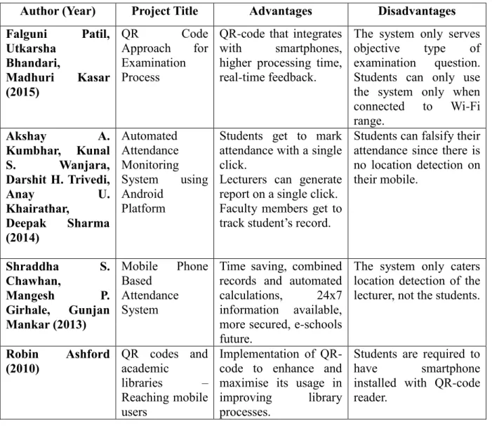
Table 2.1: Comparison of Existing Systems
Author (Year) Project Title Advantages Disadvantages
Falguni Patil, Utkarsha Bhandari, Madhuri Kasar (2015) QR Code Approach for Examination Process
QR-code that integrates with smartphones, higher processing time, real-time feedback.
The system only serves objective type of examination question. Students can only use the system only when connected to Wi-Fi range. Akshay A. Kumbhar, Kunal S. Wanjara, Darshit H. Trivedi, Anay U. Khairathar, Deepak Sharma (2014) Automated Attendance Monitoring System using Android Platform
Students get to mark attendance with a single click.
Lecturers can generate report on a single click. Faculty members get to track student’s record.
Students can falsify their attendance since there is no location detection on their mobile. Shraddha S. Chawhan, Mangesh P. Girhale, Gunjan Mankar (2013) Mobile Phone Based Attendance System
Time saving, combined records and automated calculations, 24x7 information available, more secured, e-schools future.
The system only caters location detection of the lecturer, not the students.
Robin Ashford (2010) QR codes and academic libraries – Reaching mobile users Implementation of QR-code to enhance and maximise its usage in improving library processes.
Students are required to have smartphone installed with QR-code reader.
9
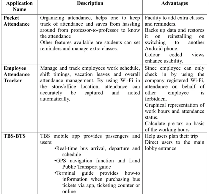
Table 2.2: Comparison of Existing Mobile Applications Application
Name
Description Advantages
Pocket Attendance
Organizing attendance, helps one to keep track of attendance and saves from hassling around from professor-to-professor to know the attendance
Other features available are students can set reminders and manage extra classes.
Facility to add extra classes and reminders.
Backs up data and restores it on reinstalling on switching to another Android phone.
Colour coded views enhance usability.
Employee Attendance Tracker
Manage and track employees work schedule, shift timings, vacation leaves and overall attendance management. By using Wi-Fi in the store/office location, attendance can accurately be captured and noted automatically.
Since employee can only check in by using the company registered Wi-Fi, attendance on behalf of other employee is forbidden.
Graphical representation of work hours and attendance status.
Calculate pre-tax on basis of the working hours
TBS-BTS TBS mobile app provides passengers and
users:
• Real-time bus arrival, departure and schedule
• GPS navigation function and Land Public Transport guide
• Terminal guide provides how-to information when purchasing bus tickets via app, ticketing counter or online
Help users plan their trip Direct users to the main lobby entrance
10
CHAPTER 3
METHODOLOGY
3.1 IntroductionThis chapter discusses the methodology of this system which includes the model used for developing the system, Gantt chart and system requirement. The development model and Gantt chart are known as the basic step to plan and execute the project systematically and makes sure the progress is on track. Therefore the --- model has been chosen. Each phase will be elaborated later in the chapter. To help understanding the system better, this chapter also explains the system designs which are Context Diagram and Data Flow Diagram and database design which are Entity Relationship Diagram and database scheme.
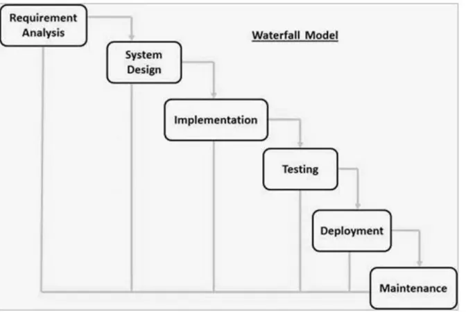
3.2 Waterfall Methodology Model
Waterfall Methodology Model works well for small projects where requirements are very well understood. It is also referred to as a linear-sequential life cycle model. It is very simple to understand and use. In “the Waterfall” approach, the whole process is divided into six separate phases. Each phase has specific deliverables and a review process. The review process is to determine if the project is on the right path and whether or not the project is to be continued or discarded. Each of these phases will have to be completed before the next phase can begin. In this model, the phases do not overlap. Based on the reasons stated above, I chose to use this methodology since it is closely related and can be easily implemented to develop my proposed project entitled Bus Passenger Tracker Application on Mobile Phone.
11 The phases involved in the Waterfall Methodology are:
Requirement Gathering and Analysis System Design
Implementation
Integration and Testing Deployment of System Maintenance
12 3.2.1 Requirement Gathering and Analysis
All possible requirements of the system to be developed are captured in this phase and documented in a requirement specification document. In this project, requirements are captured by doing researches on previous works and existing systems. Literature review is done to get more information and requirements to be fulfilled. It is also done by comparing techniques, algorithms and methods to implement in this project. As I mentioned above, I would like to propose a Mobile application therefore some researches on existing Mobile apps are also being done to get the requirements needed in the system. At the end of this phase, objectives, scopes and limitation of works are determined.
3.2.2 System Design
The requirement specifications from first phase are studied and the system design is prepared. This system design helps in specifying hardware and software requirements and helps in defining the overall system architecture of the Mobile app. At the end of this phase, the Context Diagram (CD) and Data Flow Diagram (DFD) are specified to get better understanding on how the data flows in the project system. Entity-Relationship Diagram (ERD) and database scheme are also determined to capture how data is kept in the database. Lastly, the interface sketches are determined to get a better view on the client-side requirements.
3.2.3 Implementation
With inputs from the system design, the project is then developed using Android Studio, MySQL and Xampp Server. Xampp server is the localhost used to be the server. All development of the interfaces is done in Android Studio as to get the product of Android application and MySQL is the database used for this project.
13 3.2.4 Testing
All the units developed in the implementation phase are tested to detect any failures and errors in the project. If there is any, the testing is repeated until the problems are solved.
3.2.5 Deployment of System
Once the testing is done, the project is deployed in the customer environment or released into the market. It is done in order to make sure the project meets the requirements determined at the beginning of the project development phase.
3.2.6 Maintenance
This stage is Maintenance is done to deliver changes in the customer environment. When customer comes up with feedbacks, implementation process could be improved. This will help to measure the effectiveness of the project developed and launched in customer environment. With direct feedbacks from them, any problems or glitches arises would be handled easily and efficiently during this phase. This phase is an ongoing phase to ensure the system is in good hands and meets customer’s requirements and needs.
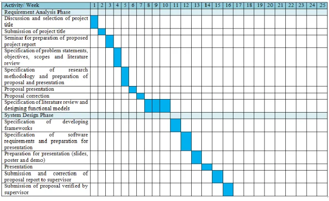
14 3.3 Gantt Chart
Figure 3.2: Gantt Chart for semester II 2016/2017
Figure 3.3: Gantt Chart for semester III 2016/2017
3.4 System Requirement 3.4.1 Hardware Laptop Printer Pendrive Android phone
15 3.4.2 Software Android Studio Xampp Java JDK Google Chrome
Microsoft Office Word 2010 Microsoft Office Powerpoint 2010
3.5 System Design 3.5.1 Framework Design
16 3.5.2 Process Model
3.5.2.1 Context Diagram
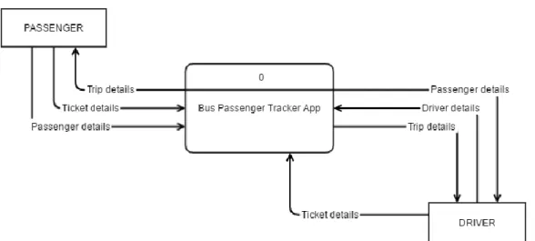
Figure 3.5: Context Diagram
As shown above, there are two entities involved in the Bus Passenger Tracker App which are Passenger and Driver. The data flow coming from the Passenger shows the data that Passenger provides to the system in order to complete the process of registering, checking trips and purchasing tickets. The trip details will be given to the Passenger once they bought the tickets.
For the Driver, registering process requires Driver’s details from the Driver into the system. Other than that, in order to complete the process of getting trip details, Driver will be provided with trip details and passenger details. This is to ensure the number of passengers who is supposed to board and get off from the bus. Lastly, to manage Passengers, Driver needs to provide the system of the tickets of Passengers.
17 3.5.2.2 Data Flow Diagram Level 0
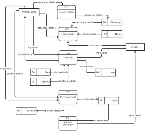
Figure 3.6: Data Flow Diagram level 0
Figure above shows the data flow diagram of level 0 with five processes and seven data stores. The two entities which are Passengers and Drivers will both be involved in two processes which are login details and check trip. As for individual entity, Passenger involves in the process register details and purchase ticket. For Driver entity, processes involved is manage passenger.
Each data store saves certain details based on the processes involved. For data store Passenger, D1, the processes that involve are register details and login from the entity
18
Passenger. Driver data store, D2, saves the details from login details process from the Driver entity.
For data store Trip, D3, the process that involves are check trip from the Passenger and Driver. Next, data store Stop, D4, which saves the details of stops in a certain trip. The process involved is check trip. For data store Tripstop, D5, it saves the details of trips and stops that involves in the process check trip from entity Passenger and Driver.
On the other hand, for data store Ticket, D6, is the data store that involved in the most important processes in this system which are purchase ticket from entity Passenger and manage passenger from entity Driver. As consequence, data store Payment, D7, saves all details that is provided in the process purchase ticket from the entity Passenger.
19 3.5.2.3 Data Flow Diagram Level 1
3.5.2.3.1 Check Trip Process
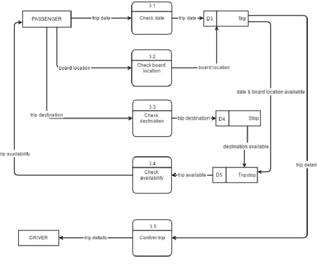
Figure 3.7: Data Flow Diagram level 1 for Check Trip process
Figure above shows the processes and data stores involve under the process check trip in data flow diagram level 0. There are five processes and three data stores involved. The processes are check date, check board location, check destination, check availability and confirm trip. On the other hand, the data stores are Trip, D4, Stop, D6, and Tripstop, D7.
20 3.5.2.3.2 Purchase Ticket Process
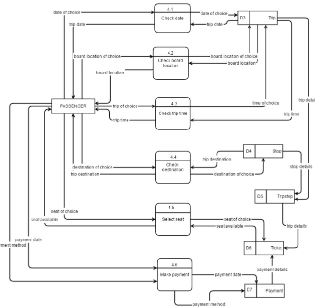
Figure 3.8: Data Flow Diagram level 1 for Purchase Ticket process
Figure above shows the processes and data stores involve under the process purchase ticket in data flow diagram level 0. There are six processes and five data stores involved. The processes are check date, check board location, check trip time, check destination, select seat and make payment. On the other hand, the data stores are Trip, D3, Stop, D4, Tripstop, D5, Ticket, D6, and Payment, D7.
21 3.5.2.4 Passenger
3.5.2.4.1 Login
Figure 3.9: Flow Chart of Passenger Login
Passengers login to get into the system.
1. Passenger type in username and password 2. Passenger clicks on the Login button.
3. The system verifies passenger’s username and password from the database.
4. If passenger details match, passenger can access the system. If not, passenger has to register first.
End Login
22 3.5.2.4.2 Register
Figure 3.10: Flow Chart of Passenger Register
Passengers register first before they can login to the system. 1. Passenger click on the Register button.
2. Passenger fill in the details required to register such as name, phone number and password.
3. The system checks if passenger already exists in database.
4. If no passenger details match, it will be saved in the database as new passenger. If yes, passengers need to login not register.
End Login Register Register? Start Yes No
23 3.5.2.4.3 Check Trip
Figure 3.11: Flow Chart of Passenger Check Trip
Passengers check trip after logs in to the system.
1. Passenger enters location they want to board and get off from the bus and date of the trip.
2. Passenger clicks on the Search button.
3. The system checks the availability of the details from the database.
4. If the trip is available, the system will display the trip details including seat numbers that are available, driver on duty and bus plate number.
Login Trip available? Trip details End Start Yes No
24 3.5.2.4.4 Purchase Ticket
Figure 3.12: Flow Chart of Passenger Purchase Ticket
Passengers purchase ticket after checking the availability of the trip wanted.
1. If passenger decides to buy the ticket for the trip, he/she clicks on the Buy Ticket button.
2. Passenger selects the seat for the trip. Login Purchase ticket? Trip available? Make payment Trip details End Start Yes No No Yes
25 3. Passenger chooses payment method. 4. Passenger clicks on the Confirm button.
5. The system will save the details of the ticket and provide passenger with a QR-code containing the purchase details.
3.5.2.5 Driver 3.5.2.5.1 Login
Figure 3.13: Flow Chart of Driver Login
Drivers login to get into the system.
1. Driver type in username and password 2. Driver clicks on the Login button.
3. The system verifies driver’s username and password from the database. 4. If driver details match, driver can access the system.
End Login
26 3.5.2.5.2 Select Trip
Figure 3.14: Flow Chart of Driver Select Trip
Drivers select trip once they login to the system. 1. Driver chooses the trip he/she is on board.
2. The system will show the trip details including the total passengers that will board and get off from the bus from each destination.
End Login
Select trip
Trip details Start
27 3.5.2.5.3 Manage Passengers
Figure 3.15: Flow Chart of Driver Manage Passenger
Drivers manage passengers during every trip.
1. Driver confirms the trip details he/she will handle such as the total passengers should board and get off from each destination they stop.
Login
All passengers arrived?
Passengers’ details Scan QR-code End Select trip Trip details Start Yes No
28
2. Driver chooses whether the activity is boarding or getting off, and clicks on the button.
3. Driver scans each passenger’s ticket to verify passengers.
4. If passengers are all aboard, driver clicks on the Done button. If not, driver clicks on the Scan New button.
5. If passengers’ details match from the database, the passenger is good to board the bus. If not, a notification will be displayed to inform the driver about the mistakes of the passenger.
29 3.5.3 Data Model
3.5.3.1 Entity Relationship Diagram
30 3.5.3.2 Database Scheme
Table 3.1: Entity Driver Attribute Name Attribute Type Attribute Size Key Description
driverID Varchar 10 Primary Key Refers to the identification number used to assign to each driver.
Example: DR0001
driverName Varchar 25 None Refers to the name of each driver.
Example: Kamil
driverPassword Varchar 10 None Refers to the password for each driver.
Example: kam1234
driverPhoneNo Integer 15 None Refers to the phone number of the driver. Example: 0185123665 Attribute Name Attribute Type Attribute Size Key Description
psgID Varchar 10 Primary Key Refers to the identification number used to assign to each passenger.
Example: PS0001
psgName Varchar 25 None Refers to the name of each
passenger.
Example: Mohamad
psgPassword Varchar 10 None Refers to the password for each passenger.
Example: moh2345
psgPhoneNo Integer 15 None Refers to the phone number of the passenger.
Example: 0193328771 Table 3.2: Entity Passenger 1
Table 3.3: Entity Stop Attribute Name Attribute Type Attribute Size Key Description
stopID Varchar 10 Primary Key Identification number used to assign to each stop. Example: ST0001
stopDestination Varchar 30 None Refers to the destination name of each stop.
31
Table 3.4: Entity Ticket Attribute Name Attribute Type Attribute Size Key Description
ticketID Varchar 10 Primary Key Identification number used to assign to each ticket purchased by passenger. Example: TC0001
ticketDate Date None Refers to the date of ticket
purchase.
Example: 2017-11-02
ticketSeatNo Varchar 5 None Refers to the seat number of purchased ticket in the bus. Example: 12
ticketPrice Decimal 3, 2 None Refers to the price of the ticket purchased.
Example: 50.00
tripstopID Varchar 10 Foreign Key Refers to the identification number used to assign to each stop destination of each trip.
Example: TS0001
psgID Varchar 10 Foreign Key Refers to the identification number used to assign to each passenger.
Example: PS0001
paymentID Varchar 10 Foreign Key Refers to the identification number used to assign to each payment made.
Example: PAY0001
Table 3.5: Entity Payment
Attribute Name Attribute Type Attribute Size Key Description
paymentID Varchar 10 Primary Key Refers to the identification number used to assign to each payment made.
Example: PAY0001
paymentDate Date None Refers to the date of payment
made.
Example: 2017-05-02
paymentMethod Varchar 20 None Refers to the method of payment chosen by passenger. Example: Credit Card
32
Table 3.6: Entity Trip Attribute Name Attribute Type Attribute Size Key Description
tripID Varchar 10 Primary Key Refers to the identification number used to assign to each trip.
Example: TR0001
tripTime Time None Refers to the time of the trip
scheduled.
Example: 21:30:00
tripFrom Varchar 30 None Refers to the location of where the passenger wanted to board the bus.
Example: Muar
tripDestination Varchar 30 None Refers to the destination that the passenger wanted to get off. Example: Jertih
tripBusPlateN o
Varchar 10 None Refers to the number of the bus plate of the trip.
Example: WCB4455
driverID Varchar 10 Foreign Key Refers to the identification number used to assign to each driver.
Example: DR0001
Table 3.7: Entity Tripstop Attribute Name Attribute Type Attribute Size Key Description
tripStopID Varchar 10 Primary Key Refers to the identification number used to assign to each stop destination of each trip. Example: TS0001
tripID Varchar 10 Foreign Key Refers to the identification number used to assign to each trip.
Example: TR0001
stopID Varchar 10 Foreign Key Identification number used to assign to each stop.
33 3.5.4 Interface Design
3.5.4.1 Home Screen
Figure 3.17: Interface design for Home screen 3.5.4.2 Passenger
3.5.4.2.1 Login
34 3.5.4.2.2 Register
Figure 3.19: Interface design for Register screen
3.5.4.2.2 Check Trip
Figure 3.20: Interface design for Check Trip screens
35 3.5.4.2.2 Purchase Ticket
Figure 3.21: Interface design for Purchase Ticket screens 3.5.4.3 Driver
3.5.4.3.1 Login
36 3.5.4.3.2 Register
Figure 3.23: Interface design for Register screen 3.5.4.3.3 Trip Menu
37
CHAPTER 4
CONCLUSION
4.1 IntroductionThis chapter discusses the conclusion and expected result to solve problems arises that leads to the development of this Bus Passenger Tracker App.
4.2 Expected Result
This application is expected to be a Mobile app and could help Drivers mainly to manage passengers in terms of tracking them of the activity boarding and getting off at their destination. Besides that, this application is targeted to Passengers so that it help ease them in terms of purchasing tickets instead of going to the counter they could just buy it from their Mobile phone. I also hope that the implementation of QR-code in this application would work well with the whole system flow.
4.3 Conclusion
After much discussion and considerations, the scope of this application is narrowed down and I hope that the development of this application will help solve problems related to the users from the public transport area especially of express bus services. The main problem that rises is that passengers might have fell asleep and miss their destination. As for the Drivers, they might miss the tracking of passengers who should get down at a certain stop. Therefore, Bus Passenger Tracker App is proposed and hoped to be developed.
38
REFERENCE OR BIBLIOGRAPHY
Research PapersSIVAKAMI, N. (2016). COMPARATIVE STUDY OF BARCODE, QR-CODE AND RFID
SYSTEM IN LIBRARY ENVIRONMENT. International Journal of Academic
Research in Library & Information Science, 2(2).
Patil, F., Karvenagar, M. M. C. O. E., Maharashtra-India, P., Bhandari, U., Kasar, M., &
Maharashtra-India, P. QR Code Approach for Examination Process.
Kumbhar, A. A., Wanjara, K. S., Trivedi, D. H., Khairatkar, A. U., & Sharma, D. (2014).
Automated attendance monitoring system using android platform. International
Journal of Current Engineering and Technology, 4(2), 1096-1099.
Chawhan, S. S., Girhale, M. P., & Mankar, G. (2013). Mobile Phone Based Attendance
System. IOSR Journal of Computer Engineering, 10(3), 48-50.
Ashford, R. (2010). QR codes and academic libraries Reaching mobile users. College &
Research Libraries News, 71(10), 526-530.
Mobile Application on Google Play Store TBS-BTS:
https://play.google.com/store/apps/details?id=tbsapp.tbsbts
Employee Attendance Tracker:
39 Pocket Attendance: