Abstractions for Software Architecture
and Tools to Support Them
Mary Shaw, Robert DeLine, Daniel V. Klein,
Theodore L. Ross, David M. Young, Gregory Zelesnik
Computer Science Department
Carnegie Mellon University
Pittsburgh PA
and various other current affiliations
1Version of March 8, 1995
Abstract
Architectures for software use rich abstractions and idioms to describe system components, the nature of interactions among the components, and the patterns that guide the composition of components into systems. These abstractions are higher-level than the elements usually supported by programming languages and tools. They capture packaging and interaction is-sues as well as computational functionality. Well-established (if informal) patterns guide ar-chitectural design of systems. We sketch a model for defining architectures and present an implementation of the basic level of that model. Our purpose is to support the abstractions used in practice by software designers. The implementation provides a testbed for experi-ments with a variety of system construction mechanisms. It distinguishes among different types of components and different ways these components can interact. It supports abstract interactions such as data flow and scheduling on the same footing as simple procedure call. It can express and check appropriate compatibility restrictions and configuration constraints. It accepts existing code as components, incurring no runtime overhead after initialization. It allows easy incorporation of specifications and associated analysis tools developed elsewhere. The implementation provides a base for extending the notation and validating the model. Keywords: Software architecture, architecture description language, software system organization, architectural abstraction, software engineering
Table of Contents
1
1 . Introduction
3
2 . Model and Notation
8
2.1. Components and Connectors 9
2.2. Abstraction and Encapsulation 1 1
2.3. Types and Type Checking 1 2
2.4. Accommodating Analysis Tools 1 3
3 . UniCon: Language for Universal Connector Support
1 3
3.1. Semantics 1 4
3.1.1. Components 15
3.1.1.1. Built-in Component Types 18
3.1.1.2. Implementation of Primitive Components 21 3.1.1.3. Implementation of Composite Components 22
3.1.2. Connectors 23
3.1.2.1. Built-in Connector Types 25
3.1.2.2. Implementation of Primitive Connectors 27
3.2. Graphical Notation 2 8 3.3. Textual Notation 2 9 3.3.1. Major Constructs 29 3.3.2. Primitive Components 30 3.3.3. Composite Components 31 3.3.4. Primitive Connectors 33 3.3.5. Property Lists 34
3.4. Populating the Space of Elements 3 4
3.5. Incorporating Analysis Tools 3 5
4 . Implementation
3 9
4.1. Procedure Call and Global Data Access 3 9
4.2. Unix Pipes and Files 4 0
4.3. Remote Procedure Call 4 1
4.4. Real-Time Scheduling 4 2
5 . Experience and Analysis
4 3
5.1. Experience 4 3
5.2. Performance 4 5
5.3. Conclusion 4 6
Appendix:
4 8
1 .
Introduction
Software engineers often describe the “architectures” of their systems. These descriptions address high-level aspects of the systems such as the overall organization, the decomposition into compo-nents, the assignment of functionality to compocompo-nents, and the way the components interact. These architectural descriptions often use box-and-line diagrams and phrases such as “pipe-and-filter system” and “client-server model”.
While architectural descriptions use high-level abstractions, the corresponding implementations are written in conventional programming languages. However, composing a system from subsystems is a substantially different activity from programming the underlying algorithms and data structures. Hardware designers confront the same situation; they recognize a number of distinct design levels, each with its own design issues, models, notations, componentry, and analysis techniques [Bell & Newell 71]. In the same way, different levels of software design require different kinds of com-ponents, different ways of composing comcom-ponents, different design issues, and different kinds of reasoning. The vocabulary gap between requirements and programming is substantial. Filling the gap requires better models and notations for the intermediate step. This is the goal of the emerging field of software architecture.
The architecture of a software system defines that system in terms of components and of interactions among those components. In addition to specifying the structure and topology of the system, the architecture shows the intended correspondence between the system requirements and elements of the constructed system. It can additionally address system-level properties such as capacity, throughput, consistency, and component compatibility. Architectural models clarify structural and semantic differences among components and interactions. Architectural definitions can be composed to define larger systems. Elements are defined independently so they can be re-used in different contexts. The architecture establishes specifications for individual elements to be written in a conventional pro-gramming language. A number of commonly-used patterns, or idioms, are in widespread informal use; these architectural styles can be captured as general templates for families of related systems. This holds particular promise for domain-specific systems. [Garlan & Shaw 93, Mettala & Graham 92, Perry & Wolf 92]
Our primary considerations here are supporting architectural abstractions, localizing and codifying the ways components interact, and distinguishing among the various packagings of components that require different forms of interaction. Our focus is largely pragmatic. Our first concern has been to identify, classify, and support a variety of components and their connections. We will refine the notation and develop a formal base over time.
A sound basis for software architecture promises benefits for both development and maintenance. Design should benefit from improved abstractions, notations, and analysis. Architectural definitions should help provide good specifications for programming activities. Since the architectural def-inition also serves as the specification for system build, the specifications and code will be less likely to diverge. Maintenance should benefit in two ways. First, about half of maintenance effort is dedi-cated to understanding the system in preparation for making changes; explicit definition of the ar-chitecture should reduce this cost. Second, system arar-chitectures degrade over time; carrying the architectural definition into maintenance should reduce this tendency toward degradation.
Additional development benefits should accrue through better information to guide software reuse. Reuse is currently impeded by differences in component packaging. For example, a given
func-tionality might be packaged as a procedure, a communicating process, an object, or a filter; it might interact with other components by calls, message-passing, method invocation, or shared data. These differences in packaging are recognized only informally and are not supported by programming languages and tools; neither formal nor informal guidance shows when and how to use them. As a result, it is often unclear whether components with compatible functionality will actually be able to interact properly. Documenting a system’s structure and properties in a rigorous way has obvious advantages for maintenance. Much of the time spent on maintenance goes to understanding the existing code; this effort should be reduced substantially if the original design structure is captured clearly and explicitly. In addition, retaining the designer’s intentions about system organization should help maintainers preserve the system’s design integrity.
A growing community of researchers is focusing on software architecture. There has been long-standing interest in particular classes of architectures such as objects (focused by the OOPSLA conference), pipelines (focused by the USENIX conference), and client-server systems (a subject of intense attention in the commercial data processing arena). Early attention to the variety of idiomatic patterns of system organization and the possibility of organizing this knowledge systematically [Shaw 88, Perry & Wolf 92, Boehm & Scherlis 92, Garlan & Shaw 93] have led to enough activity to sustain workshops on architectural design [Barstow & Wolf 93], software design with strong participation from architecture [Lamb 95], patterns for design [PLoP 94], and interface definition languages [Wing 94]. Software architecture emerged as a key theme at a recent workshop on directions in software engineering [Habermann & Tichy 92]. A major effort to gain design power for specific kinds of problems addresses domain-specific software architectures (DSSAs) in several specific domains [Mettala & Graham 92, Hayes-Roth & Tracz 93]. Formalizations are beginning to emerge [Allen & Garlan 94a,b]. As a natural consequence, languages for describing architectures are emerging [Dean & Cordy 93, Rapide 93].
The need for a notation to describe how subsystems written in typical programming languages connect to form larger systems is not a new concern. In 1975, DeRemer and Kron [DeRemer & Kron 76] argued that creating program modules and connecting them together to form larger struc-tures were distinct design efforts; they created the first module interconnection language (MIL) to support the connection effort. In an MIL notation, modules import and export resources, which are named elements such as type definitions, constants, variables, and functions. Compilers for MILs ensure system integrity with intermodule type checking: they check that if one module uses a resource that another provides, the types of the resources match; that if a module declares it provides a resource, it actually does; that if a module uses a resource, it has access to that resource; and so on. Since DeRemer and Kron’s MIL, MILs have been developed for specific languages, like Mesa [Mitchell et al 79] and Ada [Campos & Estrin 78], and have provided a base from which to support software construction [Thomas 76], version control [Cooprider 79], system families [Tichy 79], and dynamic configuration [Magee et al 89]. Enough examples are available to develop models of the design space [Perry 87, Prieto-Diaz & Neighbors 86].
These early module interconnection languages require considerable prior agreement between the developers of different modules. For example, they assume that simple name matching can be used to infer inter-module interaction, that all modules are written in the same language, that all modules are available during system construction, and that module interfaces describe the other modules with which they interact. Newer work has begun to soften these restrictions. In the Darwin language, modules can be dynamically instantiated and bound at runtime [Magee et al 93]. Polygen [Callahan & Purtilo 91] augments a module interconnection language with an inference engine that deduces from a user-defined set of rules how (or whether) a system can be integrated from set of modules.
These modules can be implemented in multiple programming languages, and the machinery needed to connect them can be richer than the usual procedure linkage, for example, a software bus [Purtilo 90]. This kind of system requires expanding the notion of a MIL to include specifics about a module's implementation, such as its programming language, its hardware/operating system platform, and the communication media needed to access it; the resulting richer notation has been termed a module interconnection formalism (MIF). To build truly composable systems we must allow flexible, high-level connections between existing systems in ways not foreseen by their original developers. Essentially independently, developers of “open” software products have designed interchange rep-resentations such as PICT (line drawings), RTF (formatted text), SYLK (spreadsheet layouts), and MIF (formatted text) to allow distinct products to interact by data interchange. Although these were originally static, newer developments such as CORBA, OLE, and OpenDoc (all for objects) support dynamic sharing.
Systems often exhibit an overall style that follows a well-recognized, though informal, idiomatic pattern. Garlan and Shaw survey half a dozen of these patterns and illustrate their use in case studies [Garlan & Shaw 93]. They identify pipes and filters, data abstractions or objects, implicit invocation, hierarchical layers, repositories, and interpreters as a useful (though incomplete) set of well-known patterns, or styles, of system organization. These styles differ both in the kinds of components they use and in the way those components interact with each other. As advocates of various of these architectures explain, adherence to the rules of the style enhances both software development and
subsequent maintenance.2 The rules of the style usually restrict how to package components—e.g.,
as procedures, objects, or filters. As a result, components may not be usable in all styles; code may not reusable because its interface makes incompatible assumptions. In Unix, for example, the func-tionality of “sort” is available both in the form of a filter and in the form of a procedure.
The remainder of this paper is organized as follows: Section 2 introduces our model of software ar-chitecture and its notation; Section 3 describes UniCon, an initial language for implementing the model; Section 4 highlights its implementation; Section 5 describes our experience with UniCon.
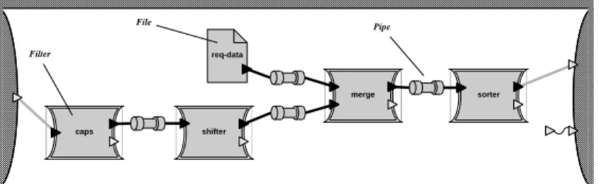
caps shifter req-data merge sorter File Filter Pipe
Figure 1. Pipe-and-filter example: the KWIC indexer.
We will use three examples throughout the paper. Although architecture diagrams often do not make visual distinctions among the interactions they depict, here we use different markings for different types of connections. The first example, shown in Figure 1, is a Unix-style pipe-and-filter system built from both filters and files, with the wrinkle that the pipeline merges two streams—a configura-tion that is difficult or impossible to describe in most shells. The system implements a KWIC (keyword in context) indexer; we have used a very similar task as a class exercise in a software ar-chitecture class [Garlan & Shaw 94]. The challenge of this example is to make complex topologies as easy to describe as simple ones.
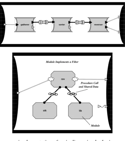
gatherer sorter reverser
rev
stk lib
Procedure Call and Shared Data
Module Module Implements a Filter
Figure 2. Heterogeneous implementation of a pipeline using both pipes and procedures. The
upper diagram is the high-level view of the system, a simple pipeline. The lower diagram shows
the implementation of the right-most component in the upper diagram.
The second example, shown in Figure 2, combines a pipe-and-filter architecture with a conventional procedural implementation of one of the filters. The challenge of this example is to compose architectural descriptions and to establish the correspondence between the abstraction of a pipeline and its implementation as calls on system procedures.
client server
Remote Procedure Call Schedulable Process
Real-Time Scheduler
Figure 3. Real-time client-server system with two schedulable tasks sharing a
computing resource. The tasks also interact via remote procedure call.
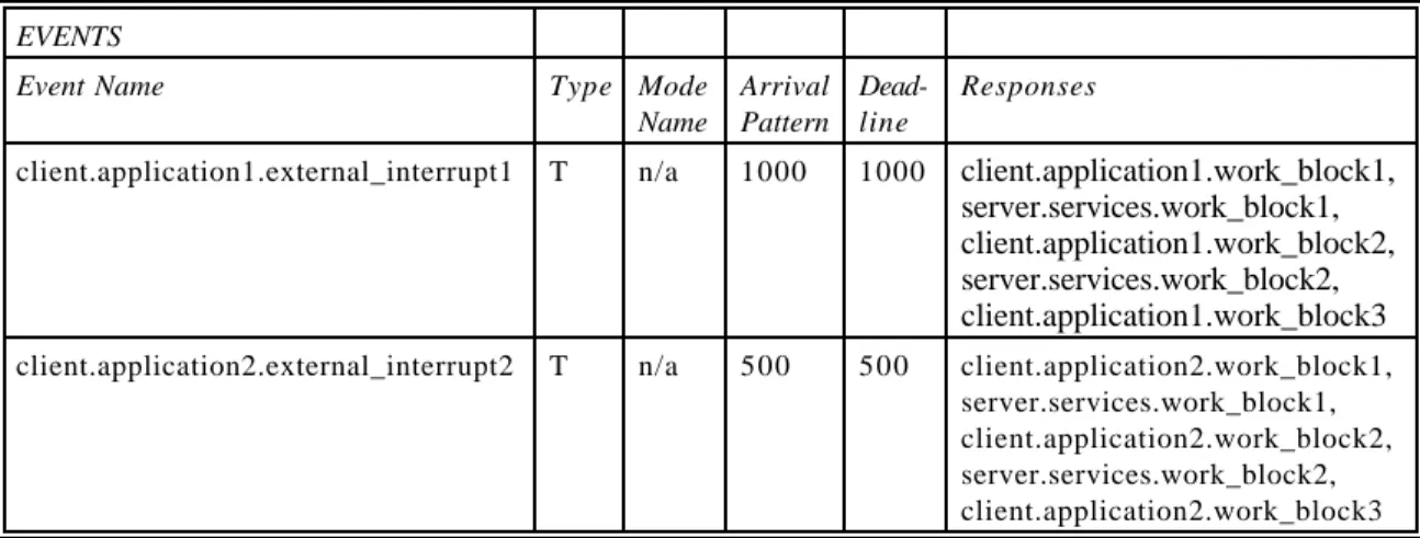
The third example, shown in Figure 3, involves coordinating time tasks. A simple periodic real-time system has a number of tasks that must run on specified schedules. More challenging scheduling problems arise when tasks interact. We use an example with two schedulable tasks that
interact through remote procedure calls. Based on a system timer, the client must periodically per-form computations which involve calling upon services provided by the server; correctness requires that these events take place at specific times. The challenge of this example is to incorporate an external analysis tool that determines the legality of the configuration (especially to make guarantees about schedulability) and to convert the code for the tasks into schedulable processes that run on a real-time operating system.
2 .
Model and Notation
This section describes an informal model for an architectural description language. The language is intended to aid designers in first defining software architectures using abstractions they find useful and then making a smooth transition to code. Our long-term objective is to fully elaborate this model and to support it with notation and tools. Currently, we are more strongly motivated by practical utility of the model than by formal foundations. At present, the model provides a frame-work for understanding our initial implementation, which is described in Section 3.
The model addresses several issues in novel ways:
• It supports abstraction idioms commonly used by designers—for example, explicitly
distinguishing different types of elements and providing type-specific analysis support.
• It specifies packaging properties as well as functional properties of components—for
example, distinguishing clearly between functionality delivered in the form of a filter from functionality delivered in the form of a procedure.
• It provides an explicit, localized home, called a connector, for information about the rules
for component interactions, such as protocols, interchange representations, and specifications of data formats for communication.
• It defines an abstraction function to map from code or lower-level constructs to higher-level
constructs. This is similar to Hoare’s technique for abstract data types [Hoare 72].
• It is open with respect to externally-developed construction and analysis tools. It supports
collection and delivery of relevant information to tool and return of results from the tool. Software system composition involves different tasks from writing modules: the system designer defines roles and relationships rather than algorithms and data structures. These concerns are suf-ficiently different to require a separate language. The architectural language must support system configuration, independence of entities (hence reusability), abstraction, and analysis of properties ranging from functionality to security and reliability [Shaw & Garlan 93]. The model must be supported by a notation.
2.1.
Components and Connectors
Systems are composed from identifiable components and connectors of various distinct types. The components interact in identifiable, distinct ways. Components roughly correspond to compilation units of conventional programming languages and other user-level objects such as files. Connectors mediate interactions among components; that is, they establish the rules that govern component in-teraction and specify any auxiliary implementation mechanism required. Connectors do not in gen-eral correspond individually to compilation units; they manifest themselves as table entries, buffers, instructions to a linker, dynamic data structures, sequences of system calls embedded in code, initialization parameters, servers that support multiple independent connections, and the like. During system design, it is important to work with good abstractions for interaction without concern for
whether their implementations are localized. It is helpful to think of the connector as defining a set of roles that specific named entities of the components must play.
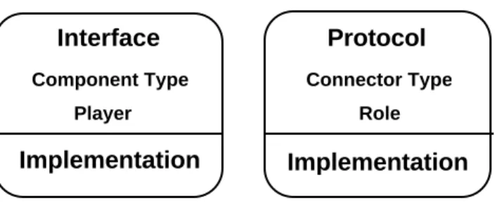
Our model thus describes software systems in terms of two kinds of distinct, identifiable elements: components and connectors. Each of the two elements has a type, a specification, and an imple-mentation. The specification defines the units of association used in system composition; the im-plementation can be primitive or composite. Figure 4 suggests the essential character of the model.
Specification Implementation Component Interface Implementation Connector Protocol Implementation
Type Component Type Connector Type
Unit of association Player Role
Element
Figure 4: Gross structure of an architecture language.
Components are the locus of computation and state. Each component has an interface specification that defines its properties. These properties include the component's type or subtype (e.g. filter, process, server, data storage), functionality, guarantees about global invariants, performance char-acteristics, and so on. The specific named entities visible in a component’s interface are its players. The interface includes the signature, functionality, and interaction properties of its players.
Connectors are the locus of definition for relations among components. They mediate interactions but are not “things” to be “hooked up;” rather, they provide the rules for hooking-up. Each con-nector has a protocol specification that defines its properties. These properties include its type or subtype (e.g. remote procedure call, pipeline, broadcast, shared data representation, document ex-change standard, event), rules about the types of interfaces it works with, assurances about the in-teraction, commitments about the interaction such as ordering or performance, and so on. The specific named entities visible in a connector’s protocol are roles to be satisfied. The interface in-cludes rules about the players that can match each role, together with other interaction properties. Components may be either primitive or composite. Primitive components may be implemented as code in a conventional programming language, shell scripts of the operating system, software veloped in an application such as a spreadsheet, or other means external to the architectural de-scription language. Composite components define configurations in a notation independent of conventional programming languages. This notation must be able to identify the constituent com-ponents and connectors, match the players of comcom-ponents with roles of connectors, and check that the resulting compositions satisfy the specifications of both the components’ interfaces and the connectors’ protocols.
Similarly, connectors may be either primitive or composite. They are of many kinds: shared data representations, remote procedure calls, data flow, document exchange standards, standardized network protocols, etc. The connectors derived directly from programming languages are typically asymmetric with two complementary roles: a procedure has a definer and multiple callers; data has an owner and multiple users; a simple data stream has one producer and one consumer. However, other, more abstract connectors may be symmetric, and their roles may be more numerous and more specific: in broadcast communication, all participants may be alike; in some event systems any
component may raise or respond to any event. The usual import/export or provides/requires relation is too restrictive to express the relations used in practice—it fails to expose important distinctions. If rich, abstract connectors are to be defined, the architectural notation must be able to express complex interaction properties. These might be as diverse as
• guarantees about delivery of packets in a communication system;
• ordering restrictions on events using traces or path expressions;
• incremental production/consumption rules about pipelines;
• the distinction between the roles of clients and servers;
• parameter matching and binding rules for conventional procedure calls;
• restrictions on parameter types that can be used for remote procedure calls; and so on.
Primitive connectors may be implemented in a number of ways: as built-in mechanisms of pro-gramming languages (e.g., procedure calls or shared data); as system functions of the operating system (e.g., certain kinds of message passing); as library code in conventional programming lan-guages (e.g., X/Motif); as shared data (e.g., Fortran COMMON or Jovial COMPOOL); as entries in task or routing tables; as a combination of library procedures and a single independent process for the connector (e.g., certain kinds of communication services); as interchange formats for static data (e.g., RTF); as initialization parameters (e.g., event period and process priority in a real-time operating system) and probably in a variety of other ways. Composite connectors may also appear in these diverse forms; we need (but do not yet have) ways to define them as well.
The example of Figure 2, heterogeneous implementation of a pipeline, uses different types of com-ponents and connectors. It also shows a composite implementation of one of the filters.
The remainder of this section deals with three issues of particular interest for general-purpose archi-tectural tools: abstraction and encapsulation (Section 2.2), the appropriate analog for types (Section 2.3), and the ability to provide access to externally-developed tools (Section 2.4).
2.2.
Abstraction and Encapsulation
For a composite element, the implementation part consists of
• a parts list (components and connectors)
• composition instructions (association between roles and players)
• abstraction mapping (relation between internal players and players of the composite)
• other related specifications (detailed properties of the parts and compositions).
This localizes and encapsulates information about the system structure rather than distributing it around the system in import/export statements. Since composition information is localized, global properties such as restrictions on topology or types of elements may be checked. Since the ab-straction mapping is explicit, we have the opportunity to allocate responsibility for the code correctly implementing higher-level connectors. Further, the composition instructions make the matching of players and roles explicit, so we can break free of name matching as the sole means of making connections, as shown in Section 3.3.3, Program 4.
Common system-composition idioms, such as pipeline, client-server, or blackboard, can be defined as idiomatic patterns, or styles, of components and connectors. These patterns describe the types of
components and connectors that can be used and may constrain the interconnection topologies. Indeed, some such styles (e.g., pipe-and-filter) are described primarily in terms of the prescribed form for communication, data sharing, or other interaction. In practice, the rules for these styles are usually implicit. The combination of localized definitions and higher-level elements makes it possible to formalize rules for styles [Abowd et al 93, Allen & Garlan 94a].
Abstract data types rely on an abstraction function to show the correspondence between the internal representation of a type and the abstract view that the user (and the specification) takes [Hoare 72]. For software architectures, abstractions are required to implement higher-level components in terms of lower-level ones. When a component or connector is not directly implemented by a programming language, its definition must explain how the abstract properties will be implemented. This might take the form of a manual or informal guidance. Even better, it could be a code template, an automated generator, or a formalization. No matter how it is represented, the definition must set out the programmer’s responsibility. When a number of components are connected to form a larger component, the players of the defined unit may be more abstract than the players of the implementation. In that case, the definition must explicitly indicate the correspondence among one or more external player (abstraction), one or more players of the constituent components, and the implementation rule. This is the abstraction mapping of the component. Similarly, abstraction mappings will be required for composite connectors. This differs from data abstraction chiefly in that it maps not only data to an abstract value but rather data plus functions to a set of abstract player types.
2.3.
Types and Type Checking
A problem similar to type checking in a programming language arises at four points in an architec-tural language. Two of these appear in the preceding discussion: the types of components and of connectors and their use in showing adherence to a style. As with any type system, types for com-ponents and connectors express the designer’s intent about how to use the element properly and are most useful when the language checks them. The types for connectors and components are not merely enumerations of unrelated items; some are closely related to others. Architectural types de-scribe expected capabilities and limit both what can appear in the construct’s specification and the legitimate ways to use the construct. Examination of real systems shows that type hierarchies of this sort are useful. For example, there are many kinds of memories (components) and many kinds of event systems (connectors). Defining type structures for these elements requires the creation of tax-onomies to catalog and structure the type variations. This is part of establishing a full model for architectural composition.
The third place where type checking appears is at the actual point of associating a component’s players with a connector’s roles. Each of the named entities in the interfaces and protocols must have enough type information and other specification to determine whether the connector definition allows the components to be associated as requested. Furthermore, a component may be used dif-ferently by different kinds of connectors. For example, a client might be indifferent to whether its servers are dedicated, shared, or distributed. An abstract pipe may be able to connect both filters and files (but not processes that share data directly). We must therefore support flexible associations between players and roles. For connectors such as procedure call that correspond directly to language constructs, this corresponds to the checks a linker may make. However, for richer, more abstract connectors the checks are more sophisticated.
The fourth opportunity for type-like checking arises when more than one architectural style is used in designing a single system. This problem also resembles that of reconciling multiple views. A comparison of architectures for a single problem [Shaw 95] explores this issue.
Components and connectors must be reusable in different settings, so it’s important to deal reason-ably with associations that are slightly mismatched. Common examples include mismatches between the order and types of a library procedure’s arguments and those of the procedure intended to call it; remapping data formats to support sharing; and the subtle differences between remote procedure calls and local procedure calls. If component’s packaging fails to match the packaging needed in use, mechanical adaptation may be possible. Our current implementation makes initial steps toward supporting adaptation in the face of mismatch.
2.4.
Accommodating Analysis Tools
Architectural descriptions should be “open” with respect to analysis tools. We must accommodate techniques that are applied at the systems level of design. These analysis tools will often be devel-oped independent of the model. They may address such properties as functional correctness, per-formance, and timing (e.g., allowable order of operations, real-time guarantees). The architectural description language should be able to interact with any analysis technique that works with infor-mation in the architectural specifications. It should be able to record the system-level specifications required by external tools as uninterpreted expressions, deliver information to the tools, receive re-sults from the tools, and incorporate those rere-sults in the architectural description.
Perhaps the most natural kind of system-level analysis is that of functional specification, which might use pre- and post-conditions to check procedure calls, for example. Perry suggested this as part of his software interconnection model [Perry 87]. Rather than building a theorem prover into the system, the system could collect the assertions from a procedure’s definer and a potential caller and invoke an external theorem prover to decide whether to allow the call. This will provide a much stronger check than either name matching or signature comparison.
A second example is rigorous analysis of the real-time properties of a system. For certain classes of systems, correctness depends on the time at which computations are completed, not just on whether the computations themselves are correct. The designer of a system must account for the computation times of individual modules as well as the complex interactions within the composition of modules. As described in Section 3.5, our implementation now supports rate monotonic analysis (RMA), which is a body of techniques for analyzing the schedulability of preemptive, fixed-priority systems. The Software Engineering Institute at Carnegie Mellon has developed a handbook for this family of analysis techniques [Klein et al 93].
3 .
UniCon: Language for Universal Connector Support
In order to gain experience with the practical details of an architectural description language, we have implemented a simplified initial system. The system, called UniCon, emphasizes the structural aspects of software architecture. It is higher-level and more general than existing mechanisms for system composition, but it is low-level compared to the model of Section 2. Specifically, the objectives of this implementation were the following:
• Address real problems of system description and composition; provide a prototype of a
• Provide uniform access to a wide range of connection mechanisms. Select connectors that are available in the local computing environment so we can concentrate on providing them, not inventing them; however, select with diversity in mind.
• Help software designers to discriminate among different types of components and different
types of connectors and to check the legitimacy of proposed configurations.
• Support both graphical and textual notations with interchange between the representations.
• Support analysis tools and specification notations developed by others. Preserve
com-patibility with programming tools in common use.
• Accept existing components. Use components written in ordinary programming languages,
including those not written for use with this tool.
• Keep added run-time costs to a minimum. Ideally all UniCon-specific elements disappear by
the time the executing system is initialized.
To speed the process of gaining experience, some simplifications were made to the model when implementing UniCon, namely:
• UniCon supports composite components but not composite connectors.
• Abstractions for components and connectors are built in, but new ones cannot yet be
defined. These built-in elements sample a diverse space, but the set is in no sense complete and a unifying taxonomy is not yet provided.
• The only primitive components at present are compilation units. Although the
implementa-tion is largely language-indifferent, C is the language supported at present.
• The syntax has not been refined for conciseness yet. It can be a bit wordy, especially when
making intermodule connections of procedures and data with no change of name.
This section begins by presenting the semantics of UniCon (Section 3.1). As an aid to intuition, this section anticipates the syntax discussion by providing a sample of the textual form of the KWIC example from Figure 1. The following two sections describe graphical syntax (Section 3.2) and textual syntax (Section 3.3); these are equivalent. We then describe the way existing code is incorporated as primitive components (Section 3.4) and the technique for using external analysis tools (Section 3.5).
3.1.
Semantics
Following the model presented in Section 2, UniCon is based on two complementary kinds of constructs: the component and the connector. Their structures are symmetric, except that composite connectors are not yet supported. Each has:
• a Name
• a specification (called an Interface for a component, a Protocol for a connector)
• a component or connector Type
• a set of global assertions in the form of a Property List
• a collection of association units: Players for components, Roles for connectors. Specific
details about these are specified in Property Lists.
• an Implementation
Each of these definitions can be understood solely in terms of its specification, and the properties of a system should be derivable from the specification of its components and connectors. This is closely
related to Lam and Shankar’s properties separability and composability [Lam & Shankar 94]. Each provides a template that is instantiated when it is used. Information about distinctions among components, connectors, players, and roles is used for an analog of type checking. The definition of language semantics is organized around this structure. Section 3.1.1 describes components, Section 3.1.2 describes connectors, and Section 3.1.3 describes type checking.
3 . 1 . 1 . Components
Components define computational capabilities. A component consists of an interface that specifies the capabilities the component exports and an implementation, which may be primitive or composite. The interface of a component must be consistent with its implementation. In the case of a primitive implementation, such as a source file or executable, this is the responsibility of the programmer. In the case of a composite implementation, the interface must be consistent with the interfaces of its member components and the protocols of its connectors; its semantics should be derivable from the interfaces of its constituents.
The interface defines the computational commitments the component can make and constraints on the way the component is to be used. The interface provides the guarantees that will hold of the behavior and performance of the component. It should be possible to use the component by refer-ence to the interface alone. The interface must include
• the component type
• assertions and constraints that apply to the entire component
• the players defined by the component, which each consist of a name and type and optional
attributes like signature, functional specifications, constraints on use, or information required specifically by a component type (e.g., port bindings of Unix file descriptors).
A component type expresses the designer's intention about the general class of functionality to be provided by the component; it restricts the numbers, types, and specifications of the Players defined by the component. The players, which form the bulk of the interface, are the visible semantic units through which the component can interact, request and provide services, or be influenced by external state or events. The interactions are mediated by the roles of connectors. The detailed specifications of the players appear in the form of property lists, which are lists of attributes and their associated values. Program 1 shows an example of the textual description of both a primitive and a composite component, which will be referenced throughout this section. Component types and their associated players are discussed below in Section 3.1.1.1.
To provide some specific intuition for the semantics, we will use the pipeline implementation of KWIC presented in Figure 1. This example’s pipeline involves four filters, one file, four pipes, and the two streams that are Players in the composed system. Three of the filters in this example have the canonical interface for a simple filter, specifying stdin, stdout, and stderr; merge, of course, has two inputs. For these filters the specification further indicates that the data on the stream is line-oriented. Program 1 shows the textual notation for two components from the KWIC example, which will be referenced throughout this section.
Component KWIC from Program 1 is an example of a system. A system is a component, usually a composite component, that is capable of independent operation in the context of a computer and its operating and runtime systems. The external specification of the system is the interface of the com-ponent. The system remains eligible for use as a component; indeed, the essence of systems inte-gration is finding ways to treat as subsystems today those things that were systems last week. A system
may interact with users and other systems. A system is closed in the sense that all the players of its
interface are bound to its execution environment; it implements a function that is discrete and
complete in the mind of its designer. This is the result of an architectural definition.
COMPONENT sort INTERFACE IS
TYPE Filter
PLAYER input IS StreamIn SIGNATURE ("line") PORTBINDING (stdin) END input
PLAYER output IS StreamOut SIGNATURE ("line") PORTBINDING (stdout) END output
PLAYER error IS StreamOut SIGNATURE ("line") PORTBINDING (stderr) END error END INTERFACE COMPONENT KWIC INTERFACE IS TYPE Filter
PLAYER input IS StreamIn SIGNATURE ("line") PORTBINDING (stdin) END input
PLAYER output IS StreamOut SIGNATURE ("line") PORTBINDING (stdout) END output
PLAYER error IS StreamOut SIGNATURE ("line") PORTBINDING (stderr) END error
END INTERFACE IMPLEMENTATION IS
VARIANT sort IN "sort" IMPLTYPE (Executable) INITACTUALS ("-f") END sort END IMPLEMENTATION END sort IMPLEMENTATION IS
/* First instantiate the parts to use */ USES caps INTERFACE upcase
USES shifter INTERFACE cshift USES req-data INTERFACE const-data USES merge INTERFACE converge USES sorter INTERFACE sort USES P PROTOCOL Unix-pipe USES Q PROTOCOL Unix-pipe USES R PROTOCOL Unix-pipe
/* Associate players of some parts to players of interface. By default, all stderrs are bound to the external stderr */
BIND input TO caps.input BIND output TO sorter.output
/* Describe the way KWIC is built from parts by directly associating players with roles */
CONNECT caps.output TO P.source CONNECT shifter.input TO P.sink CONNECT shifter.output TO Q.source CONNECT req-data.read TO R.source CONNECT merge.in1 TO R.sink CONNECT merge.in2 TO Q.sink
/* Syntactic sugar for full connections */ ESTABLISH Unix-pipe WITH
merge.output AS source sorter.input AS sink END Unix-pipe
END IMPLEMENTATION END KWIC
Program 1. A primitive and a composite component.
A component’s implementation may be either primitive or composite. Primitive implementations provide one or more ways to locate a definition in some programming language and are discussed below in Section 3.1.1.2. Composite implementations instantiate a set of components and configure them with connectors and are discussed in Section 3.1.1.3.
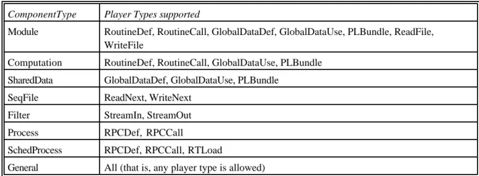
ComponentType Player Types supported
Module RoutineDef, RoutineCall, GlobalDataDef, GlobalDataUse, PLBundle, ReadFile, WriteFile
Computation RoutineDef, RoutineCall, GlobalDataUse, PLBundle SharedData GlobalDataDef, GlobalDataUse, PLBundle
SeqFile ReadNext, WriteNext Filter StreamIn, StreamOut
Process RPCDef, RPCCall
SchedProcess RPCDef, RPCCall, RTLoad
General All (that is, any player type is allowed)
Table 1. Built-in component types and their players.
3.1.1.1.
Built-in Component Types
Component types and player types are currently defined by enumeration, but extensions may be supported some day. Table 1 lists the component types currently supported and the players allowed for each. This set of component types was selected opportunistically: we wanted to reflect components and connectors used in practice and to cover as wide a variety as possible. Each of these is described in detail below.
• Component type Module corresponds to a compilation unit in a typical programming
language. The RoutineDef players correspond to exported procedures and functions. The
RoutineCall players correspond to imported procedures and functions. Similarly, GlobalDataDef and GlobalDataUse players correspond to import and export of named
data. The ReadFile and WriteFile players provide an input/output capability.3 These
players correspond directly to language constructs or system calls. However, modules frequently define one or more coherent collections of players; when designers think about the architecture of the system, they think about the use of a collection of players rather than about all the individuals. UniCon captures this with an abstract player, PLBundle, that corresponds to a set of individual players related to procedure calls or data use. Modules are intended to provide definitions that will be linked in a single name space.
• Component type Computation is a specialization of Module whose interface is restricted to
defining procedures, functions, and bundles thereof and using procedures, functions, and data defined elsewhere. It is intended to capture purely computational units that are collections of procedure definitions and calls. Similarly, component type SharedData is a specialization of Module whose interface is restricted to defining and referencing data.
• Component type SeqFile corresponds to sequential files in which lines, characters, or records
(as specified by the RecordFormat attribute) are read sequentially from the front (ReadNext) and written sequentially at the end (WriteNext).
• Component type Filter corresponds to Unix filters in which input arrives in streams and
output is produced in streams (StreamIn and StreamOut). The syntax of the stream (the structure imposed on elements in the stream) may be specified by the Signature attribute.
• Component type Process corresponds to an independently scheduled process at the
operat-ing system level. It differs from Filter in that it interacts via remote procedure calls (RPCDef
and RPCCall) rather than data flow.4 SchedProcess is a special type of Process that admits
player RTLoad that provides the information required for real-time scheduling using attributes SegmentSet, Trigger, SegmentDef, and TriggerDef.
• A General component type allows any player types, thus allowing the definition of arbitrary
components; it does not support analysis or checking. Using general components when it is possible to use more specific types defeats the purpose of component typing.
Attribute Req/Opt Merge Rule
Applies to Components
Value / Default / Syntax
InstFormals optional merge all Formal parameter list for instantiation of component. Default is no instantiation parameters. Syntax depends on rules of implementation language.
Variant optional replace all Used during instantiation of the component to select among variant implementations. Default is the first implementation provided. Syntax is name of a variant.
RecordFormat optional replace SeqFile Format of records in the file. Default is lines separated by <CR>. Syntax depends on rules of implementation language. Library optional replace Computation,
Module, SeqFile, SharedData
Changes default value of MinAssocs to 0 (i.e., allows unused players). Also provides hint to builder to generate library archive rather than simple executable form.
EntryPoint optional replace Module, Computation, Process, SchedProc
Point at which to start execution. Default is main program of module. Syntax is procedure name.
Priority optional replace SchedProc Priority at which real-time operating system should run the process. Default is highest. Syntax is integer.
Processor optional replace All Processor on which the component will be executable. Default is local processor. Syntax is processor name.
SegmentDef required replace SchedProc Definition of a segment of code in the implementation of a real-time component. Syntax is name followed by ‘;’ followed by execution time in seconds. No default
TriggerDef optional replace SchedProc Definition of external stimulus that activates a segment. Syntax is name followed by ‘;’ followed by period of stimulus in seconds. No default.
RPCTypesIn optional merge Process, SchedProc
Auxiliary information required to derive language-independent type information for RPC generator.
RPCTypedef optional replace Process, SchedProc
Auxiliary information required to derive language-independent type information for RPC generator.
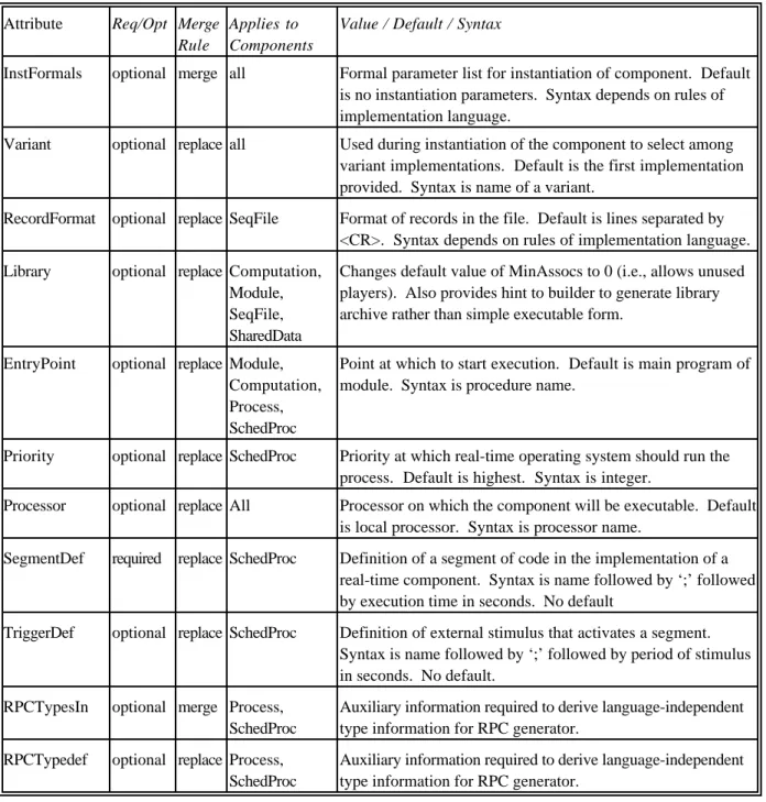
Table 2. Attributes that apply to components.
Attributes in property lists provide further specification of a component. Each attribute is relevant to one or more component types and may be required or optional; it must specify what to do if multiple values are specified for the attribute, for example, in different property lists. The possibilities are currently to use the most recent (replace), to construct a list of all values (merge), and to refuse multiple definitions (error). Certain attributes pertain to a component as a whole. For example, in cases where it is possible to provide instantiation parameters to an entire component, those are
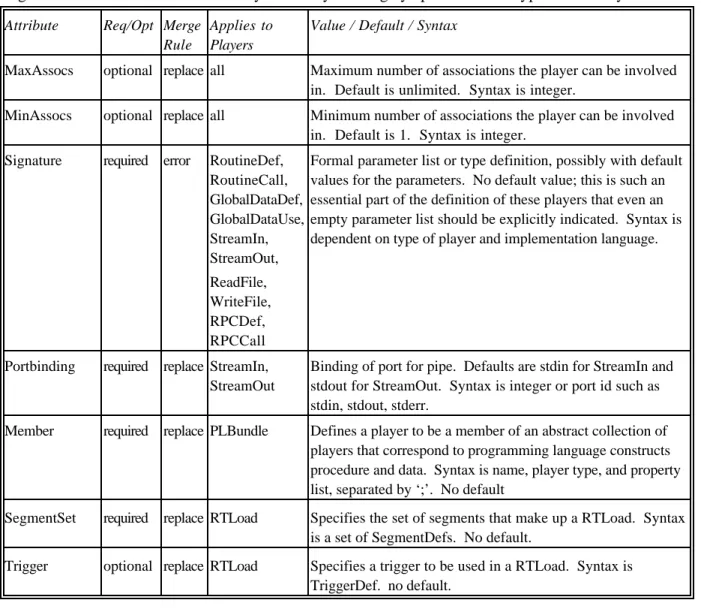
provided with the property list for the component itself. Table 2 lists component attributes, and Table 3 gives the attributes defined for Players. They are largely specific to the type of the Player.
Attribute Req/Opt Merge
Rule
Applies to Players
Value / Default / Syntax
MaxAssocs optional replace all Maximum number of associations the player can be involved in. Default is unlimited. Syntax is integer.
MinAssocs optional replace all Minimum number of associations the player can be involved in. Default is 1. Syntax is integer.
Signature required error RoutineDef, RoutineCall, GlobalDataDef, GlobalDataUse, StreamIn, StreamOut, ReadFile, WriteFile, RPCDef, RPCCall
Formal parameter list or type definition, possibly with default values for the parameters. No default value; this is such an essential part of the definition of these players that even an empty parameter list should be explicitly indicated. Syntax is dependent on type of player and implementation language.
Portbinding required replace StreamIn, StreamOut
Binding of port for pipe. Defaults are stdin for StreamIn and stdout for StreamOut. Syntax is integer or port id such as stdin, stdout, stderr.
Member required replace PLBundle Defines a player to be a member of an abstract collection of players that correspond to programming language constructs procedure and data. Syntax is name, player type, and property list, separated by ‘;’. No default
SegmentSet required replace RTLoad Specifies the set of segments that make up a RTLoad. Syntax is a set of SegmentDefs. No default.
Trigger optional replace RTLoad Specifies a trigger to be used in a RTLoad. Syntax is TriggerDef. no default.
Table 3. Attributes that apply to Players.
3.1.1.2.
Implementation of Primitive Components
Primitive components are implemented directly in the code of some programming language or data stored in files. They are made available to UniCon by providing an appropriate specification as a wrapper. Code may be represented as source, object, or executable; other representations will be added as required.
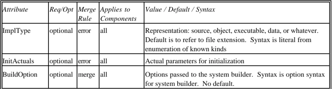
Since multiple representations for a component may be available (for example, both source and object code), UniCon allows multiple representations, called variants, to be specified. When a primitive component is instantiated, the Variant attribute can be used to select the preferred variant. This capability can be exploited, for example, to provide variants with different performance prop-erties or variants with special support for debugging or monitoring. Table 4 shows the attributes defined for primitive implementations of components.
The KWIC indexer example is constructed from primitive filter components, like the Sort component shown in Program 1. The interfaces of the component filters are very similar to the interface for the
whole system. The implementations are primitive, and since they correspond directly to executable Unix filters, they have only one variant.
Attribute Req/Opt Merge
Rule
Applies to Components
Value / Default / Syntax
ImplType optional error all Representation: source, object, executable, data, or whatever. Default is to refer to file extension. Syntax is literal from enumeration of known kinds
InitActuals optional error all Actual parameters for initialization
BuildOption optional merge all Options passed to the system builder. Syntax is option syntax for system builder. No default.
Table 4. Attributes defined for primitive components.
3.1.1.3.
Implementation of Composite Components
Composite components provide the capability of building up progressively larger subsystems from components of (potentially different) types. A composite implementation must provide three kinds of information:
• The parts: Instantiations of the components and connectors from which the composite
component is constructed.
• The configuration: Specification of how the instantiations of connectors link the
instantiations of components, i.e. the associations5 between players and roles.
• The abstraction: Specification of how the players of the interface will be associated with
players of the implementation.
Since more than one instance of an element (component or connector) definition may be used in a single implementation, these definitions are templates to be instantiated for each use. Each instan-tiation may provide a property list that further constrains the attributes of the element. The merge
rule of the attribute determines the interpretation when multiple values are provided for an attribute.
The configuration of the composite implementation is defined by explicitly connecting players and roles. Each match is checked by comparing the type of the player against the Accepts attribute of the component, ensuring that maximum and minimum connection counts are satisfied.
The interface of the component being defined specifies the players that the component must provide; these are the ExternalPlayers. In the implementation, players are provided when components are instantiated; these are the InternalPlayers. The abstraction step defines ExternalPlayers in terms of
InternalPlayers. Two cases arise:
• In the simple case, one of the constituent components defines an InternalPlayer of the same
type and specification as the ExternalPlayer. In this case, simple name binding suffices to export the player through the interface.
• The more complex case arises when an ExternalPlayer is of a type not directly supported by
the programming language. In this case the ExternalPlayer must be implemented by more concrete InternalPlayers of the implementation. This is the case, for example, when a StreamIn is implemented with calls on library routines that read standard input. It will be-come increasingly common as we add more abstract players that are realized as calls on sev-eral specific procedures according to set protocols. The definition of such an abstract connector must specify the functionality that the implementation must provide. In this case,
the binding must indicate the name of the ExternalPlayer in the interface and show how InternalPlayers satisfy the required functionality. The special attribute MapsTo identifies the InternalPlayer(s).
Warnings about ExternalPlayers and roles that are not associated with InternalPlayers are given as appropriate. Setting the MinAssocs attribute of a Player to 0 indicates that it is normal for the Player to be unassociated. A Library attribute will soon be provided to indicate that many players will normally remain unassociated.
In the implementation of KWIC in Program 1, four filters and a file are used to build a system that is itself a filter. The definition of pipe used here corresponds to unix: as indicated in Table 5, it supports the players of sequential files as well as filters. The implementation is composite and has three parts. First, it instantiates the parts to be used. Next, it binds the StreamIn of the first filter (caps) to the StreamIn of the interface and the StreamOut of the last filter (sorter) to the StreamOut of the interface. (This is an example of the simple case where ExternalPlayers are bound to InternalPlayers of the same type.) Finally, it configures the system by indicating which inputs and outputs are connected by which pipes. The example shows two ways to do this: by individually associating players to roles of explicitly instantiated pipe connectors and by a single statement that implicitly instantiates the pipe and makes all connections at once. The former allows the connections to be grouped by the designer’s choice; the latter assures the reader that no other roles of the connector are connected elsewhere. The mechanical character of the example provides ample motivation for using the graphical interface described in Section 3.2.
3 . 1 . 2 . Connectors
Connectors mediate interactions among components. A connector consists of a protocol that spec-ifies the class of interactions the connector provides and an implementation. Connectors define the protocols and mechanics of interaction together with any additional mechanisms required to carry out the interaction: auxiliary data structures, initialization routines, and so on. The connector def-inition is also the location for specifications of required behavior such as interchange representations and the internal manifestation (e.g. sequence of procedure calls) of the connector in the code of a component. At present, all connectors are primitive and their implementations are therefore individually crafted within the UniCon implementation.
The protocol defines the allowable interactions among a collection of components and provides guarantees about those interactions. To do this it defines roles, or the responsibilities of various par-ties that set requirements for the players of components whose interactions are to be governed by the connector. The author of the component is responsible for ensuring that these responsibilities are satisfied by the implementation. The protocol must include:
• the connector type
• assertions that constrain the entire connector (for example, rules about timing or ordering);
these are the commitments about the interaction that the protocol supports
• the roles that participate in the protocol; each consists of a name and type and optional
attributes like signature, functional specifications, or constraints on their use.
A connector type expresses the designer's intention about the general class of connection to be provided by the connector; it restricts the numbers, types, and specifications of the Roles provided by the connector. In particular, some roles may require players, some may be optional but constrained if present, and some may be restricted to match certain player types. A good example from a programming language would be the generator as defined in Alphard [Shaw 81].
The roles are the visible semantic units through which the connector mediates the interactions among components. Their types are primitive typing units. They are used to identify the players that must cooperate in a successful interaction. Roles identify the kinds of interactions a connector can establish—the kinds of components it can work with and the player types it can handle. When a role appears in a protocol, it must specify a name and role type and may optionally specify other at-tributes; some of these attributes may be required in particular instances. The detailed specifications of the roles appear in the form of property lists, or lists of attributes and their associated values. Roles form the bulk of the protocol.
CONNECTOR Unix-pipe PROTOCOL IS
TYPE Pipe
ROLE source IS source MAXCONNS (1) END source ROLE sink IS sink
MAXCONNS (1) END sink END PROTOCOL IMPLEMENTATION IS BUILTIN END IMPLEMENTATION END Unix-pipe
Program 2. A primitive connector.
At present, only primitive implementations of connectors are supported. Program 2 gives the textual definition of the pipe connector for the KWIC example. These connectors only have primitive bodies, so there is no issue of matching. The bodies are at present defined in an ad hoc manner. Primitive connectors are not further interpreted at the architecture level except through their proto-cols. This might be as simple as a rule that procedure calls must match procedures in the fashion allowed by the programming language or as complex as a network protocol supported by several independent communication servers.
3.1.2.1.
Built-in Connector Types
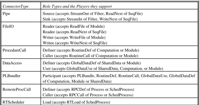
Connector types and role types are now defined by enumeration, but extensions may someday be supported. Table 5 lists the connector types currently supported, the roles allowed for each, and the players that the roles can support. As for component types, we chose them opportunistically. For connectors, especially, we wanted to deal with the practical details of actual implementations.
Some of these are more closely related than others (the same is true for components). FileIO and Pipe are abstractions over the same Unix mechanisms. The language would benefit from type tax-onomies that show these relations. In this case, for example, it would not be necessary to identify all three component types for which GlobalDataUse may be a player. Moreover, General could be treated as the root of a taxonomy rather than as a special case.
Connector type Pipe provides the Unix abstraction of pipe. Depending on whether it establishes an interaction between pipes or files, it chooses the correct implementation mechanism. When a system is constructed of many pipes, filters, and files, UniCon creates an initialization routine that starts up the filters with all the proper port bindings; it handles arbitrary topologies correctly. The KWIC example of Figure 1 is based on pipes. Specifically, it uses Unix-pipes, which are of type Pipe. These particular pipes are restricted to a single association, so an attribute is provided to override the default. The protocol specifies two roles, corresponding to the two ends of the pipe.
ConnectorType Role Types and the Players they support
Pipe Source (accepts StreamOut of Filter, ReadNext of SeqFile) Sink (accepts StreamIn of Filter, WriteNext of SeqFile) FileIO Reader (accepts ReadFile of Module)
Readee (accepts ReadNext of SeqFile) Writer (accepts WriteFile of Module) Writee (accepts WriteNext of SeqFile)
ProcedureCall Definer (accepts RoutineDef of Computation or Module) Caller (accepts RoutineCall of Computation or Module) DataAccess Definer (accepts GlobalDataDef of SharedData or Module)
User (accepts GlobalDataUse of SharedData, Computation, or Module)
PLBundler Participant (accepts PLBundle, RoutineDef, RoutineCall, GlobalDataUse, GlobalDataDef of Computation, Module or SharedData)
RemoteProcCall Definer (accepts RPCDef of Process or SchedProcess) Caller (accepts RPCCall of Process or SchedProcess) RTScheduler Load (accepts RTLoad of SchedProcess)
Table 5. Built-in connector types and their roles.
Connector type FileIO sets up sequential file reading and writing.
Connector types ProcedureCall and DataAccess provide the architectural abstractions that correspond the usual inter-module connections supported by programming languages. In addition to making these connectors visible at the architecture level, they do type checking of the defines/uses relation on the basis of signatures rather than the spelling of identifier names.
Connector type PLBundler supports the abstraction for connecting a collection of procedure or data definitions with their calls or uses. It abstracts from ProcedureCall and DataAccess in the same way that PLBundle abstracts from the corresponding player definitions.
Connector type RemoteProcCall corresponds to the RPC facility supplied by the operating system. It relieves the user of the need to work explicitly with complex libraries and generator processes.
Connector type RTScheduler mediates competition for processor resources among a set of real-time processes. It requires an operating system with appropriate real-time capabilities. When rate-monotonic scheduling is selected, UniCon invokes a schedulability analysis to check the real-time correctness of the set of processes to be scheduled. This facility is described in Section 3.5
Further specification of each connector is achieved by providing values for certain attributes. These attribute-value associations are made by property lists. Each attribute is relevant to one or more connector types. It may be required or optional. It must specify what to do if multiple values are specified for the attribute, for example in different property lists. The possibilities are currently to use the most recent (replace), to construct a list of all values (merge), and to refuse definitions after the first (error).
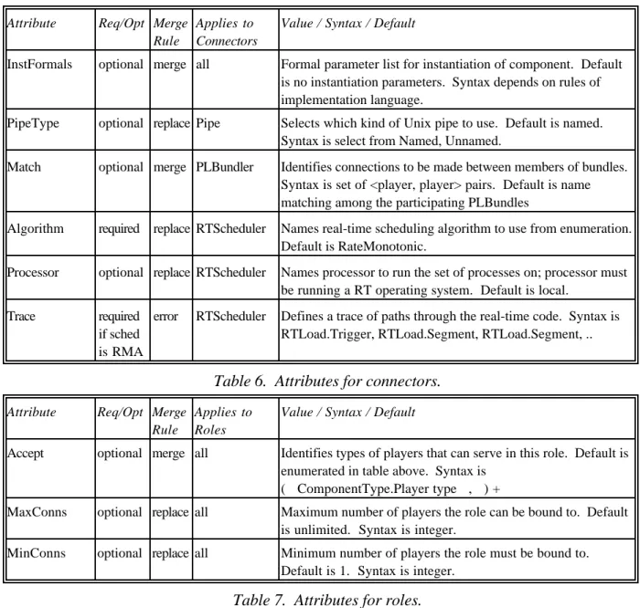
Certain attributes pertain to the connector as a whole. For example, a design decision such as which type of Unix pipe or which real-time scheduling algorithm to use applies to the entire connector. Table 6 shows the attributes of entire connectors. Table 7 lists the attributes defined for Roles. The attributes are largely specific to the type of the Role.
Attribute Req/Opt Merge Rule
Applies to Connectors
Value / Syntax / Default
InstFormals optional merge all Formal parameter list for instantiation of component. Default is no instantiation parameters. Syntax depends on rules of implementation language.
PipeType optional replace Pipe Selects which kind of Unix pipe to use. Default is named. Syntax is select from Named, Unnamed.
Match optional merge PLBundler Identifies connections to be made between members of bundles. Syntax is set of <player, player> pairs. Default is name matching among the participating PLBundles
Algorithm required replace RTScheduler Names real-time scheduling algorithm to use from enumeration. Default is RateMonotonic.
Processor optional replace RTScheduler Names processor to run the set of processes on; processor must be running a RT operating system. Default is local.
Trace required if sched is RMA
error RTScheduler Defines a trace of paths through the real-time code. Syntax is RTLoad.Trigger, RTLoad.Segment, RTLoad.Segment, ..
Table 6. Attributes for connectors.
Attribute Req/Opt Merge
Rule
Applies to Roles
Value / Syntax / Default
Accept optional merge all Identifies types of players that can serve in this role. Default is enumerated in table above. Syntax is
( ComponentType.Player type , ) +
MaxConns optional replace all Maximum number of players the role can be bound to. Default is unlimited. Syntax is integer.
MinConns optional replace all Minimum number of players the role must be bound to. Default is 1. Syntax is integer.
Table 7. Attributes for roles.
3.1.2.2.
Implementation of Primitive Connectors
The implementation details about these connectors are provided in Section 4. Unlike components, the connectors do not correspond to discrete items to be linked in or referenced. In the current system, ProcedureCall and DataAccess connectors use the mechanisms (e.g., the linker) of the un-derlying language and leave no residue at execution time; if renaming is done by a composition, it is handled with compile-time macros.
Pipe and FileIO connectors use Unix ports, pipes, and files; an initialization procedure sets up the appropriate topology and starts the processes.
For the RemoteProcCall connector, UniCon automatically generates, compiles, and links the “glue code” for the processes doing the RPCs. This glue code collects the arguments of the remote pro-cedures and converts them to messages that are passed between processes.
For the RTScheduler connector, UniCon collects the Trigger and Segment specifications from the RTLoad players and passes them to the Rate Monotonic analysis tool for analysis of the trace
in-formation. To establish the connection, UniCon adds Real-Time Mach scheduling information to the processes to make them schedulable in the operating system and makes them available on the target machine for initialization.
For all processes running under Mach or Real-Time Mach, UniCon turns the code specified in the implementations of the Process or SchedProcess component into heavyweight processes. This is not required for Unix processes since they are already heavyweight processes.
3.2.
Graphical Notation
In practice, designers rely heavily on diagrams for describing system architectures. Therefore a graphical form of the notation is essential. The graphical notation for UniCon and its user interface allow specifications to be built incrementally. Figures 1, 2, and 3 were produced with the graphical interface, except that the annotations were added manually.
Our emphasis is on defining composite components. Each component corresponds to a window in which the parts, configuration, and abstraction of a composite component are laid out. The frame of a component’s definition window is shaded to suggest the type of the component that is being implemented. The designer instantiates components and connectors from a menu of defined types and positions them. Smaller icons on the edges of the components and ends of the connectors rep-resent players. More identifying information is supplied dynamically as the designer’s focus moves from one element to another. Each element has an associated detailed definition that can be opened and manipulated during design.
As far as is possible, different types of components, players, and connectors are distinguished iconically. The graphical editor invokes the checking facilities of the language processor to check as much as possible while the diagram is being developed, so errors are largely prevented rather than corrected after the fact. Figure 2-b contains two features of particular note: The clouds on the edges of the rev component indicate that an abstraction binding is being used, and the chain links on the connectors between rev and the two supporting components show use of definition bundles rather than explicit connections of individual procedures.
The tool does take an initial step toward resolving type mismatches as discussed in Section 2.3. When a connection of RoutineCall and RoutineDef with mismatched signatures is proposed, the editor selects a connector of type TranslatingProcedureCall. Though not yet fully implemented, this mechanism will allow the connection and provide the designer with a code template that translates the calling signature to the declared signature. The designer must fill in the code to correctly perform the translation. When the graphical composition is complete, the tool generates a correct and complete textual representation.
3.3.
Textual Notation
UniCon also supports a conventional textual form. Since the language is still fluid, we have chosen a very simple syntax that relies on property lists to provide information. More elaborate concrete syntax will be selected when we relax some of the restrictions noted at the beginning of Section 3 and move on to a successor language. The collected syntax appears in Appendix A.
The textual notation is interconvertible with the graphical notation. On an initial conversion from text to graphics the screen position attributes will be missing, so manual positioning will be required. Any conversion from graphics to text will yield property lists that include screen position attributes; these are parsed but ignored by the tool.