PROCEEDINGS OF ECOS 2016 - THE 29TH INTERNATIONAL CONFERENCE ON EFFICIENCY, COST, OPTIMIZATION, SIMULATION AND ENVIRONMENTAL IMPACT OF ENERGY SYSTEMS JUNE 19-23, 2016, PORTOROŽ, SLOVENIA
In-building waste water heat recovery: an urban
scale method for energy saving assessments
Alexandre Bertrand a,c, Riad Aggoune b and François Maréchal c
a Luxembourg Institute for Science and Technology - LIST, ERIN, Belvaux, Luxembourg,
alexandre.bertrand@list.lu (corresponding author)
b LIST, ITIS; Belval, Luxembourg, riad.aggoune@list.lu
c Swiss Federal Institute of Technology of Lausanne - EPFL, Sion, Switzerland,
francois.marechal@epfl.ch Abstract:
Residential domestic hot water (DHW) energy consumption represented 16% of the EU household heating demand in 2013. Due to the improvement of the building envelop, it is expected to increase significantly, with values between 20% to 32% in single family buildings, and between 35% to almost 50% in multifamily buildings. Currently, this energy is lost to the environment after its use, but it can be recovered by waste water heat recovery (WWHR) systems inside buildings (in-building solution). However, the potential of such solutions has not been assessed in detail for different types of buildings or at urban scale. Also, the characterisation of waste water streams has barely been addressed.
A method quantifying the energy saving potential at urban scale of in-building WWHR systems in residential buildings is therefore proposed. The characterisation of residential waste water streams as to mass flow and temperature level is also addressed. The method is applied to a real case-study, where the impacts of shower and grey water heat exchangers are assessed. Grey water heat recovery for hot water preheating yields up to 18% and 27% fuel savings for passive single family houses and multifamily buildings, respectively. With the detailed characterisation of the waste water streams, the quantification of the energy savings through heat recovery is improved. The energy savings achieved by in-building WWHR systems can be more precisely compared with other optimisation measures. The outcomes of urban energy assessments concerning waste water heat recovery are also improved, as the results at building level are aggregated to the considered geographical scope. The proposed method therefore complements current urban energy assessments with a detailed analysis of in-building waste water heat recovery systems.
Keywords:
In-building heat recovery, Residential waste water characterisation, Urban energy assessment.
1. Introduction
In 2014, the European Union [1] decided to reduce its greenhouse gas emissions by 40% and to improve its energy efficiency by 27% for 2030. 26.8% of the EU28 final energy consumption in 2013 originated from the household sector, coming only second to transport (31.6%), with a total of 3’441 TWh [2]. Residential domestic hot water (DHW) consumption represents, with 442 TWh, about 16% of the EU household heating demand [3], energy generally lost to the environment. With the improvement of the building envelop, DHW is about to play an increasingly important role, with a contribution to total heating demand between 20 to 32% in highly-insulated single family buildings, and between 35 to almost 50% in multifamily buildings [4, 5].
One possibility to reduce DHW-related energy consumption is to recover the heat from the various waste water (WW) streams inside the building (in-building solution). The energy saving and cost impacts of shower heat exchangers (HE) have already been assessed [6, 7, 8, 9] as well as the combinations of shower heat exchanger with heat pump [10, 11, 12, 13] or with solar energy [10]. A review on heat recovery from residential waste water streams combined with heat pumps was recently conducted by Hepbasli et al. [14]. However, specific data on mass flow and temperature level of the various residential WW streams is, in general, not given [5]. Detailed waste water stream characterisation methods according to inhabitant and household number or end-use
occurrence have also not been explored, although this could significantly improve the quality of the assessments of waste water heat recovery (WWHR) systems. In addition, the majority of these previous works did not assess the energy saving or cost impacts of their configurations under varying building characteristics. Meggers and Leibundgut [5] and Slys et al. [15] did consider varying inhabitant number for the energy saving and costs assessments of shower HE systems but did not address other parameters like building type or varying heating demand according to building age. The relevance of these HE systems, both in terms of financial and energy saving impacts, might however change according to the specificities of the building. Finally, the assessment of in-building WWHR at the level of in-building blocks, districts or a city has been little explored. The very few publications [16, 17] applied a simplified top down approach, i.e. used a ‘flat-rate’ energy saving value or the result from one building type, respectively. More specific results would be obtained by generating the outcomes for the single buildings, then aggregating the separate savings to the required geographical scale.
Considering these shortcomings, the objective of this work is to propose a novel method for the energy saving assessment of residential, in-building, WWHR configurations at urban scale (building block, street, district or city), considering building specificities. The characterisation of various residential waste water streams in function of inhabitant and household number as well as end-use occurrence is also addressed. The geoallocation of the streams, which allows a spatial differentiation of the results and therefore the detection of areas with specific potentials as well as the aggregation and representation of the data according to building blocks, streets or districts, is indirectly covered with the characterisation method.
The main contribution of the exposed method is therefore to improve the accuracy of energy assessment methods of in-building waste water heat recovery systems.
The proposed method is described in section 2. The particular focus of this work is on shower and hot grey (waste water not loaded with urine and faeces) water heat exchangers for the preheating of fresh water (FW). The various potential configurations are assessed as to their related energy savings using pinch analysis. The method is then deployed in a real case-study to the city of Esch-sur-Alzette (Luxembourg) in section 3. Section 4 discusses advantages, shortcomings and contributions of the presented work, while conclusions are drawn in section 5.
2. Method
The characterisation methodology of hot grey water (GW) streams is deployed in section 2.1. The assessment of shower and grey water heat exchanger configurations, considering potential energy savings and implementation constraints, is given in section 2.2. Calculation methods to determine the energy savings of these configurations are presented in section 2.3.
2.1 Domestic grey water streams characterisation
Domestic hot water usage and the corresponding grey water streams must first be characterised. Each end-use is defined by mass flow, duration and frequency of use per capita. It is also important to defined the typical temperature level and, if possible, geographical position. Bertrand et al. [4] conducted a review of European DHW end-use models covering these parameters, proposed a method to geoallocate these streams, and characterised those as a function of the inhabitant and household numbers in a given urban area.
Concerning waste water streams, characterisation data is generally very scarce [5]. Assuming the water losses during use phase can be neglected, part of the DHW data described in [4] can be used to calculate by mass balance the waste water flow, duration and frequency of GW streams. Lau et al. [17] proposed an equation characterising grey water temperatures, considering hot and fresh water temperature. However, no method on how to quantify the temperature loss coefficient is provided. The data given below is therefore obtained from literature, from own observations, or by proposing various assumptions. The data is described for the main waste water streams occurring in
the bathroom (shower, bathtub, sink use for personal hygiene), kitchen (manual dishwashing or dishwasher, sink use for hand washing) and the laundry (washing machine).
2.1.1 Bathroom
Concerning bathroom streams, complementary data is mostly required for waste water temperature levels.
Focusing on shower streams, Wong et al. provides an equation correlating the drain temperature with the outdoor temperature in Hong Kong [7]. However, considering that the city has a humid sub-tropical climate, with outdoor temperatures in winter reaching 15°C, this correlation may not be applicable to other climates. Especially in colder climates, it can be expected that, for reason of comfort, the bathroom temperatures remain constant independently of outdoor conditions. Therefore, literature data on temperature differences between shower head and tray, although scarce, are summarised in Table 1.
Table 1. Shower head and drain temperature differences.
Source [-] Date of publication [-] Country [-] Temperature difference [K] Eslami-Nejad and Bernier [6] 2009 Canada 4
Mui et al. [7] 2010 China 2 – 5 Guo et al. [8] 2012 China 5 – 8 Passivhaus Institut [18] 2014 Germany 5 Jiang et al. [13] 2015 China 6 – 8
Concerning baths, no waste water temperature data is indicated in the literature. However, in order to obtain at least an order of magnitude of the temperature decrease before and after bathing, a difference between 0.5 and 1.5 K was measured, under different conditions, in a bathtub using a mercury thermometer (Table 2).
Table 2. Bathtub water temperatures.
Bath duration [min] Room temperature [°C] Start temperature [°C] End temperature [°C] Temperature difference [K] 20 21 37.0 36.0 1 23 22 43.0 42.5 0.5 26 22 40.5 39.0 1.5 29 22 38.0 36.5 1.5 35 22 39.0 38.0 1
For the bathroom sink, the drain temperature can be assumed to be equal to that of the DHW stream, as the distance and retention time in the sink are too small to induce a relevant temperature decrease.
2.1.2 Kitchen
Concerning the kitchen grey water streams, the water volume and use frequency as well as water temperature of dishwashers must be characterised.
Not all of the dishwasher water is rejected at high temperature [19]. In the case of the prewash phase, the water retains its initial temperature. Household water consumption statistics can therefore not be used to characterise the hot waste water volume of this type of equipment. De Paepe [20] indicates various waste water temperature levels varying between 34 and 61°C for the different washing phases (washing, hot rinsing, cold rinsing, etc.). However, this publication may be outdated, as the authors mention a water consumption of approximately 33 l per washing cycle, which is more than twice the water use indicated in other works, e.g. [21]. Lee and Jeong [22] provide the energy profile of the dishwasher waste water in function of time, while various other authors show the internal dishwasher temperature profiles, with washing temperatures varying
between 55 and 60°C [23, 24, 25, 26]. Unfortunately, information as to the related waste water volume is not provided.
Saker et al. [19], however, proposes fresh water and temperature profiles for an A rated, 12 places dishwasher from Blomberg/Beko, which allows the characterisation of the volume and temperature of the hot waste water streams of the various phases (Table 3). The water volumes indicated below are averaged values from the ranges indicated by the authors, to simplify the heat recovery calculations. It is assumed that the prewash water is rejected at ambient temperature to the sewer. The temperature of the washing phase is in line with the findings of Richter [27], who observes that 52% of users prefer to select cleaning temperatures at 65°C and higher. The condensing water obtained from the final drying phase is not considered, as the energy rejected is negligible compared to the other phases [22].
Table 3. Dishwasher waste water streams characterisation, according to Saker et al. [19].
Phase [-] Waste water quantity[kg] Waste water temperature [°C]
Wash 5 65
Cold rinse 3.5 50
Hot rinse 4 45
Concerning the kitchen sink, short uses (e.g. for hand washing) can be assumed as inducing no temperature losses due to the small duration time. For hand dish washing, considering that the plates enter the water at room temperature and that the water is retained in the sink, a certain temperature decrease needs to be considered. As no data is available, a difference of 5 K is assumed for the calculations below.
2.1.3 Laundry
The only waste water streams allocated to the laundry are those related to the washing machine. Data on ownership rate, wash cycle number, water consumption per wash cycle and most frequent wash temperature for several countries and continents (40°C in Western Europe) are given by Pakula and Stamminger [28]. However, similarly to the dishwasher, not all of the water used by a washing machine is heated up [19]. The use of national household water consumption statistics to quantify the hot waste water volumes should therefore be avoided. Persson [29] provides a temperature profile inside the machine, but the related waste water quantities are not given. Lau et al. [17] indicate a hot water (HW) temperature of 49°C for this type of equipment. Saker et al. [19] provides fresh water and temperature profiles for a mid-range, A rated, 7 kg washing machine manufactured by Blomberg/Beko. Of the total 65 l water use, about 10 l are heated and rejected to the sewer at a temperature around 37°C. The remaining water is not heated.
2.2 Configuration assessment
This section covers the energy saving potential of shower (2.2.1) and building (2.2.2) waste water heat exchangers, considering different configurations. In terms of energy consumption, the shower is, by far, the main DHW stream in households [30] and specific heat exchangers for this end-use are already on the market. Grey water heat recovery systems, including storage units, are also available. The potential for heat recovery is analysed using pinch analysis. This method, developed by Linnhoff [31], assesses the potential between cold streams to be heated up (fresh water) and hot streams to be cooled down (waste water from the shower and other hot end-uses). The results are represented in a power / temperature diagram, with the cold composite curve (CCC) as blue, bottom, curve and the hot composite curve (HCC) as red, top, curve. The point where both curves meet is the pinch point. The overlapping segment of the two curves indicates the heat recovery potential, while the non-overlapping segments represent the remaining cooling (left segment) and heating (right segment) requirements for the cold and hot streams, respectively. It should be noted that the diagrams below represent the corrected temperatures, meaning that the CCC is shifted upwards and the HCC shifted downwards, each by half of the minimum temperature difference
dTmin considered. The values expressed below in percentage are the ratio of heat recovery power (overlapping segment) to the total heating power requirements (cold composite curve).
2.2.1 Shower heat recovery configurations 2.2.1.1 Pinch analysis
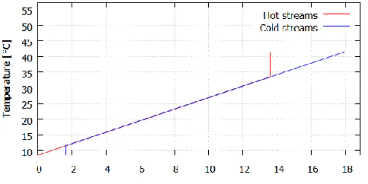
Fresh water and sewer temperatures of 10°C, shower head and tray temperatures of 40°C and 35°C, respectively, and a mass flow of 0.13 kg/s are used here for the shower pinch analysis, unless stated otherwise. In order to consider a highly efficient heat exchanger, a minimum temperature difference dTmin of 3 K is considered. The heating load amounts to 16.3kW.
As first assessment, a balanced flow, where both fresh and waste water have the same mass flow of 0.13 kg/s, is considered. The shower power demand would be covered to 74% by heat recovery (Fig. 1), and the waste water would exit at 11.5°C (temperature at the bottom left point where the two curves do not overlap anymore). The fresh water temperature would reach 32°C only instead of the required 40°C, thus necessitating the addition of hot water. However, this is not feasible as the maximum mass flow is already reached. Therefore, the value of 74% heat recovery is a theoretical maximal potential theoretically achievable for a shower heat exchanger, with the specific parameters given above.
Fig. 1. Pinch analysis - balanced conditions.
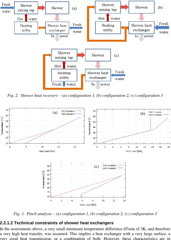
In practice, three shower heat recovery configurations are conceivable [32]. The first system (configuration 1, Fig. 2 (a)) consists in using the shower waste water to preheat the part of the shower mass flow that is directed to the heating utility for the hot water production. Fig. 3 (a) shows the HCC and CCC for the same conditions as above, but with a cold water flow of 0.09 kg/s heated up to 55°C instead (see section 2.3.1.1 for the calculation of the unbalanced hot water mass flow). 49% of the required heating power can be covered by heat recovery, with the waste water going to the sewer at 19°C.
Another possibility (configuration 2, Fig. 2 (b)) is to preheat the full shower mass flow of 0.13 kg/s, and to split it between a preheated ‘cold’ water stream and a preheated water stream going to the boiler for hot water production. In this case, the heat recovery potential reaches 74% (Fig. 3 (b)). As the full fresh water mass flow circulates through the heat exchanger, the heat transfer is maximised. The waste water would exit at 11.5°C.
The next configuration (configuration 3, Fig. 2 (c)) consists in preheating only the part of the shower mass flow that normally comes in as cold water. With a higher ‘cold’ water temperature, the hot water demand is therefore reduced. Similarly to configuration 1, this configuration is constrained by the mixing at the tap, as the mass flow and temperature after mixing must match the shower flow and temperature requirements. This implies that the fresh water in the heat exchanger has a lower mass flow than the shower stream, and that the waste water is led to the sewer at a temperature of 19°C. The heat recovery covers 48% of the heating power (Fig. 3 (c)).
Fig. 2. Shower heat recovery – (a) configuration 1, (b) configuration 2, (c) configuration 3
Fig. 3. Pinch analysis – (a) configuration 1, (b) configuration 2, (c) configuration 3
2.2.1.2 Technical constraints of shower heat exchangers
In the assessments above, a very small minimum temperature difference dTmin of 3K, and therefore a very high heat transfer, was assumed. This implies a heat exchanger with a very large surface, a very good heat transmission, or a combination of both. However, these characteristics are in practice constrained by costs (important payback time for large HE) and space availability. The minimum temperature difference of shower heat exchangers available on the market is much higher, so that the actual heat recovery potential is lower than the ones obtained from the pinch analysis.
(b) (a) (c) (b) (a) (c)
Shower heat exchanger are either mounted vertically as replacement of waste water piping, or horizontally in or very close to the shower tray. Although vertical HE yield a high heat recovery efficiency and can be used for configuration 1 and 2, they require one to two meters of space below the shower tray, which might not be given as retrofit solution for multifamily buildings or single family houses with showers at the ground floor [9]. A horizontal heat exchanger has low space requirements and is easily installed when combined with a shower basin [33]. However, due to their small surface, they have a lower heat recovery efficiency. They are mostly intended for configuration 3, where preheated fresh water is mixed with hot water, as their use with configuration 1 or 2 would require a cold water connection to a heating utility close by (decentral heating unit), which is not always given.
Considering these constraints, it is suggested to select a configuration from section 2.2.1.1 according to the type of heat exchanger, which is constrained by the building type. While horizontal heat exchangers are not constrained in terms of space, vertical heat exchangers should not be considered for multifamily buildings, unless more detailed information as the building structure and layout are available.
2.2.2 Grey water heat recovery
The pinch analysis for grey water heat recovery is conducted below considering a single family building with 2.98 inhabitants equipped with a bathtub and a dishwasher (average number of inhabitants per household and end-uses occurrence rates from the case-study below). The description of the streams is given in detail in the case study section 3.1.1. To perform a first theoretical assessment of the heat recovery potential, the pinch analysis is conducted by summing the daily energy values of the DHW and WW streams and averaging these sums over one hour to obtain the related thermal load. To remain consistent with section 2.2.1.1, a dTmin value of 3K is applied.
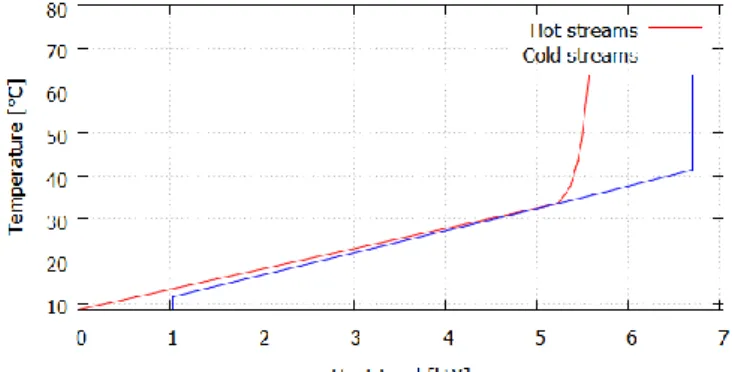
Fig. 4 represents the HCC and CCC of the simplest heat recovery configuration, where direct heat transfer occurs between the specific DHW and WW streams. Heat recovery would cover 80% of the power demand, with the remaining waste water being rejected at 13°C. However, this outcome is only a theoretical potential, as the DHW demand and WW rejection do not occur simultaneously. A storage system must therefore be considered for either the waste water streams or for the hot water production.
Fig. 4. Pinch analysis- transfer between domestic hot water and waste water streams.
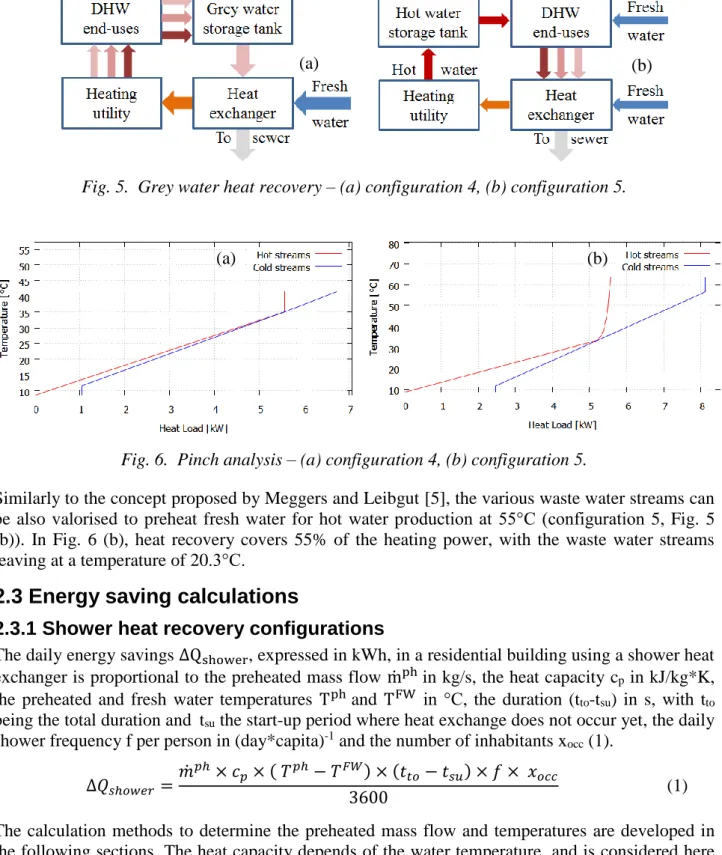
Using a waste water storage tank (configuration 4, Fig. 5 (a)) for fresh water preheating, the thermal power can be reduced by 80%, with the waste water mixed to a temperature of 37°C (see section 2.3.2.1 for the tank temperature calculation) before being rejected to the sewer at a temperature of 14°C (Fig. 6 (a)). While yielding a high efficiency, this configuration is difficult to actually implement, as it implies a direct and specific connection between utility and DHW end-uses, which would drastically increase installation and equipment costs.
Fig. 5. Grey water heat recovery – (a) configuration 4, (b) configuration 5.
Fig. 6. Pinch analysis – (a) configuration 4, (b) configuration 5.
Similarly to the concept proposed by Meggers and Leibgut [5], the various waste water streams can be also valorised to preheat fresh water for hot water production at 55°C (configuration 5, Fig. 5 (b)). In Fig. 6 (b), heat recovery covers 55% of the heating power, with the waste water streams leaving at a temperature of 20.3°C.
2.3 Energy saving calculations
2.3.1 Shower heat recovery configurations
The daily energy savings ∆Qshower, expressed in kWh, in a residential building using a shower heat exchanger is proportional to the preheated mass flow ṁphin kg/s, the heat capacity cp in kJ/kg*K,
the preheated and fresh water temperatures Tphand TFW in °C, the duration (tto-tsu) in s, with tto
being the total duration and tsu the start-up period where heat exchange does not occur yet, the daily
shower frequency f per person in (day*capita)-1 and the number of inhabitants xocc (1).
∆𝑄𝑠ℎ𝑜𝑤𝑒𝑟 = 𝑚̇𝑝ℎ× 𝑐𝑝× ( 𝑇𝑝ℎ− 𝑇𝐹𝑊) × (𝑡𝑡𝑜− 𝑡𝑠𝑢) × 𝑓 × 𝑥𝑜𝑐𝑐
3600 (1)
The calculation methods to determine the preheated mass flow and temperatures are developed in the following sections. The heat capacity depends of the water temperature, and is considered here to be 4.18 kJ/kg*K. Fresh water temperature depends on the location. Values for shower duration and frequency in various EU countries can be found in [4].
The start-up time tsu of both inline horizontal and vertical heat exchangers has been measured to be
5 seconds [34]. In order to consider the circulation through the shower pipe and head as well as the shower tray, additional 10 seconds can be assumed for the horizontal configuration, leading to a start-up phase tsu of 15 seconds. For vertical HE, a start-up phase of 90 seconds is used [35].
(b) (a)
(b) (a)
2.3.1.1 Configuration 1
For configuration 1, the preheated mass flow ṁph corresponds to the hot water mass flow ṁHW which is obtained by considering mass (2) and energy (3) conservation equations, with the temperatures expressed in K (4). 𝑚̇𝑠ℎ𝑜𝑤𝑒𝑟 = 𝑚̇𝐻𝑊+ 𝑚̇𝑝ℎ (2) 𝑇𝑠ℎ𝑜𝑤𝑒𝑟× 𝑚̇𝑠ℎ𝑜𝑤𝑒𝑟= 𝑇𝐻𝑊× 𝑚̇𝐻𝑊+ 𝑇𝑝ℎ× 𝑚̇𝑝ℎ (3) 𝑚̇𝐻𝑊 = 𝑚̇ 𝑠ℎ𝑜𝑤𝑒𝑟× ( 𝑇𝑠ℎ𝑜𝑤𝑒𝑟− 𝑇𝑝ℎ) ( 𝑇𝐻𝑊− 𝑇𝑝ℎ) (4)
For unbalanced flows, the preheated fresh water temperature Tph must be calculated iteratively, based on the fresh water mass flow and using the relations between mass flow, temperature difference and heat transfer coefficient U in W/m2*K, heat exchanger surface A in m2 and the logarithmic mean temperature difference dTm, expressed in K (5).
𝑄̇𝐻𝐸 = 𝑚̇𝐹𝑊 × 𝑐
𝑝× ( 𝑇𝑝ℎ− 𝑇𝐹𝑊) = 𝑈 × 𝐴 × 𝑑𝑇𝑚 (5)
The heat exchanger surface A can either be calculated or obtained from the manufacturer. For the calculation of the logarithmic mean temperature difference dTm and the heat transfer coefficient U, it is referred to the literature for the calculation procedure (e.g. [36]), as the detailed description would be out of scope of the current urban-scale work.
2.3.1.2 Configuration 2
Concerning the configuration 2, the preheated mass flow equals the shower mass flow. For balanced flows, the preheated water temperature Tph can be recalculated from the efficiency data provided by certification institutions, e.g. KIWA in the Netherlands (www.kiwa.nl) or Passivhaus Institut in Germany (www.passiv.de).
2.3.1.3 Configuration 3
For configuration 3, the preheated mass flow corresponds to the (cold) fresh water that is mixed in the shower tap with the hot water. It is calculated considering the mass (2) and energy (3) conservation equations, as function of the shower mass flow and the system temperatures (6).
𝑚̇𝑝ℎ = 𝑚̇
𝑠ℎ𝑜𝑤𝑒𝑟×
( 𝑇𝐻𝑊− 𝑇
𝑠ℎ𝑜𝑤𝑒𝑟)
( 𝑇𝐻𝑊− 𝑇𝑝ℎ) (6)
The preheated water temperature Tph is obtained from subtracting the minimum temperature difference dTmin of the considered heat exchanger from the shower waste water temperature.
2.3.2 Grey water heat recovery
The heat recovery potential from grey water can be determined using the problem table method, an algorithmic form of the pinch analysis. As raised in section 2.2.2, the storage of either WW or hot water must be considered, as the simultaneous occurrence of the various DHW and WW streams is not given.
2.3.2.1 Configuration 4
The daily average tank temperature is obtained with the energy conservation equation similar to (3), considering the sum of the product between temperature and mass of the various grey water streams and the tank mass (7).
𝑇𝑡𝑎𝑛𝑘 =∑ (𝑇𝐺𝑊 𝐺𝑊× 𝑚𝐺𝑊)
The grey water thermal power is calculated with the tank energy content potentially rejected at sewer temperature, over a period of one hour (8).
𝑄̇𝑡𝑎𝑛𝑘 =𝑚𝑡𝑎𝑛𝑘× 𝑐𝑝× (𝑇𝑡𝑎𝑛𝑘− 𝑇𝑠𝑒𝑤𝑒𝑟)
3600 (8)
Similarly, the power Q̇eof the various DHW end-uses e is obtained by aggregating the daily energy requirements considering the occupant or household numbers of the building for the same period of time. Eq. (9) is given as example for DHW end-uses related to inhabitant behaviour (e.g. shower).
𝑄̇𝑒 = ∑𝑥_𝑜𝑐𝑐(𝑚𝑒)× 𝑐𝑝× (𝑇𝑒− 𝑇
𝐹𝑊)
3600 (9)
2.3.2.2 Configuration 5
The daily hot water power demand is related to the sum of the hot water mass volumes 𝑚̇𝑒𝐻𝑊 of each DHW streams e, considering the use duration de and frequency fe, as well as the fresh and hot
water temperatures TFW and THW (10).
𝑄̇𝐻𝑊 =∑(𝑚̇𝑒𝐻𝑊× 𝑑𝑒× 𝑓𝑒) × 𝑐𝑝× (𝑇𝐻𝑊− 𝑇𝐹𝑊)
3600 (10)
The hot water mass flow ṁeHW, considering mass and energy conservation equations, is proportional
to the temperatures of the end-use Te, hot water THW and fresh water TFW as well as the end-use
mass flow 𝑚̇𝑒 (11).
𝑚̇𝑒𝐻𝑊 = 𝑚̇ 𝑒 ×
( 𝑇𝑒− 𝑇𝐹𝑊)
( 𝑇𝐻𝑊− 𝑇𝐹𝑊) (11)
The thermal power of the various waste water streams are calculated with (9).
3. Case-study
Two scenarios assessing the energy savings of shower and grey water heat recovery systems in the residential buildings of the city of Esch-sur-Alzette are presented in this case-study. In addition, the potential for low energy and passive buildings is specifically addressed, by considering an average inhabitant number of 2.98 for a single family building and 12 for a multifamily building, with an average household number of 1 and 5.48, respectively. In scenario 1, single family buildings are equipped with a vertical heat exchanger to preheat fresh water for both shower and hot water preparation (configuration 2). A horizontal shower heat exchanger is selected for multifamily buildings to preheat the cold fresh water, mixed with hot water in the shower tap (configuration 3). In scenario 2, grey water is recovered for hot water production and storage (configuration 5), as the majority of the heating systems are considered to be equipped with a hot water storage tank [37]. The domestic hot water requirements, based on GIS data converted into a PostgreSQL database [38], have been characterised in a former work [4]. It is assumed that 100% of the households are equipped with a washing machine.
The domestic hot and grey water streams are described in section 3.1.1, while in section 3.1.2 and 3.1.3 the specificities of the two scenarios are given for the showers and grey water heat recovery systems, respectively. The results are presented in section 3.2.
3.1 Calculations
3.1.1 Hot waste water parameters
The fresh water and hot water temperatures are considered to be 10°C and 55°C, respectively. The waste water streams are characterised according to section 2.1. A temperature decrease of 5 K for manual dishwashing and for showers is assumed. Use frequencies of dishwashers and washing
machines are taken from [21] and [28], respectively. The waste water mass of the streams of these two utilities are considered to be rejected within one minute [19]. The input data is summarised in Table 4.
Table 4. Domestic hot and grey water streams characterisation.
Stream [-] Appliance [-] Use level [-] End-use temp. [°C] Drain temp. [°C] Mass flow [kg/s] Duration [s/capita* day] Frequency [1/capita*day] [1/hhold*day] Hand wash Kitchen sink Household 35 35 0.08 15 3.15 Dish washing Kitchen sink Household 55 50 0.13 48 3.15 Washing and shaving Bathroom sink Inhabitant 35 35 0.04 40 1.35
Shower Shower Inhabitant 40 35 0.13 510 0.70 Bath Bath Inhabitant 40 39 0.20 600 0.044 Wash Dish
washer
Inhabitant n.a. 65 0.08 (5kg)
60 0.3
Cold rinse Dish washer
Inhabitant n.a. 50 0.06 (3.5kg)
60 0.3
Hot rinse Dish washer Inhabitant n.a. 45 0.07 (4kg) 60 0.3 Cloth washing Washing machine Household n.a. 37 0.17 (10kg) 60 0.45
n.a. – not applicable
3.1.2 Scenario 1 - shower heat recovery
The horizontal shower heat exchangers applied to multifamily buildings in scenario 1 are of type Ecoshower 900/ DSS shower drain channel WWHR model 900/4, which has an efficiency of 54% under stead-state conditions [34]. With a pipe length of 6.8m and an external diameter of 0.016 m (data from Wagner Solar GmbH), the power under unbalanced conditions is 4,86 kW. The fresh water exits the heat exchanger at a temperature of 27°C with a mass flow of 0.07 kg/s. For the vertical heat exchanger of the single family buildings, an efficiency of 66% for a 2 m pipe system is considered [34]. The water is preheated to a temperature of 26.5°C.
3.1.3 Scenario 2 - grey water heat recovery
Concerning scenario 2, the problem table algorithm is applied to each residential building of the database, in order to calculate the heat recovery potential. A minimum temperature difference of 5K is used for this scenario.
3.2 Results
3.2.1 Energy savings at city level
The yearly total heating demand of the residential sector of Esch-sur-Alzette amounts to 189 GWh, of which 23.8 GWh is for domestic hot water demand [4]. By aggregating the energy savings of each residential building, obtained from (1) for scenario 1 and the heat recovery potential from the problem table method for scenario 2, the absolute and relative savings at city scale for the two scenarios can be determined (Table 5).
Table 5. Scenario 1 and 2 energy savings at city scale.
Scenario Absolute energy savings [GWh]
Relative energy savings, related to total heating demand [%]
Relative energy savings, related to DHW demand [%]
1 7.0 3.7% 29.4%
2 12.0 6.3% 50.6%
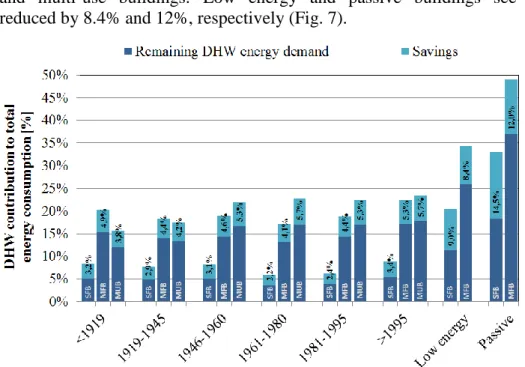
3.2.2 Energy savings according to building type and period of construction
The relative energy savings (light blue) and remaining DHW energy requirements (dark blue), related to the total fuel consumption for heating of the various residential building types (single family building – SFB, multifamily building - MFB and multi-use building – MUB) and construction period for the two scenarios are represented in Fig. 8-9. The percentages indicated are the savings, relative to the total fuel consumption, obtained from the implementation of the WWHR configurations.
The use of a vertical heat exchanger reduces the heating consumption of single family buildings between 2.2 and 3.4%, and between 9 and 14.5% for low energy and passive buildings. With a horizontal shower heat exchanger, energy savings between 3.8 and 5.7% can be reached in multifamily and multi-use buildings. Low energy and passive buildings see their energy consumption reduced by 8.4% and 12%, respectively (Fig. 7).
Fig. 7. Scenario 1: Shower heat recovery - relative energy savings.
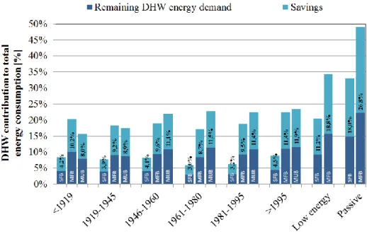
With grey water heat recovery for hot water preheating, savings between 3.0 and 4.5% in single family buildings and between 8.0 and 11.9% for multifamily and multi-use buildings are obtained. Applying this solution to low energy and passive buildings leads to savings between 11 and 18% for single family buildings and between 19 and 27% for multifamily buildings (Fig. 8).
4. Discussion
A new, detailed, method assessing at urban scale the energy savings from in-building waste water heat recovery in residential buildings is proposed.
One of the main strengths of the deployed work is the characterisation and geoallocation of the major waste water streams as to mass flow and temperature level, in function of inhabitant and household numbers. In addition, energy saving assessments are conducted by considering several building-specific parameters, e.g. end-use occurrence, building type, which highlights the particular relevance (or not) of WWHR solutions for specific buildings. Finally, energy saving impacts of
WWHR configurations can be calculated at building block, district or city by the aggregation of the data obtained at building level.
Fig. 8. Scenario 2: Grey water heat recovery - relative energy savings.
One limitation of the exposed work consists in the low availability and level of technical, geographical and socio-economic details of the input data. In addition, knowledge of the occurrence of retrofitting constraints, which influences configuration selection, is limited. Due to the scale of the problem, the proposed calculation method is also simplified and do not reflect transient conditions encountered in storage systems, thermal losses by distribution or efficiency drop of the heat exchangers over time, which further reduce the energy saving potential.
Concerning data availability, further information on mass flows and temperature levels in function of building type and economic level of the household must therefore be acquired. With socio-economic data available, the application of Geographically Weighted Regression would further improve the quality of the assessment as the geoallocation of certain end-uses would better reflect reality. Also, sensitivity analysis shall be applied to the method in order to quantify the uncertainty of the outcomes. In addition, the constraints limiting the implementation of the considered waste water heat recovery systems must be better described as to their occurrence rate and the type of building concerned, in order to improve the selection of WWHR systems. Finally, more detailed calculation methods must be developed for the considered urban scale, although resolution time might then become an issue.
The main significance of the present work is the detailed energy saving assessment, considering building specificities and various waste water streams, of residential WWHR potential at urban scale. The exposed method leads to several main contributions in the field of urban energy analysis and optimisation.
At building level, residential waste water streams are more specifically characterised by considering inhabitant and household numbers as well as various domestic hot water end-uses. The potential assessment for waste water heat recovery, independently of the configuration (in-building, in-sewer or at waste water treatment plants) is therefore qualitatively improved, which, under similar assumptions, allows a better comparison with other energy saving measures. In addition, the integrated optimal selection of heating utility configurations, as proposed by e.g [39] and [40], is extended with the characterisation of the waste water streams as additional heat source. This alternative is of particular relevance for buildings where surface or geothermal heat exchangers are constrained , e.g. by space.
At urban scale, energy assessments at building block, district or city levels are qualitatively improved and spatially more differentiated, as the outcomes are obtained by aggregating the specific results of each single buildings. Urban energy optimisation assessments, focusing so far on thermal insulation and heating utility selection, can be expanded to include waste water heat recovery as additional optimisation measure. By relating the impact of these different measures to the total heating demand, the ranking and selection of optimisation scenario by decision takers are improved.
Future developments should focus on the qualitative and quantitative improvement of waste water streams and constraints data. Also, the proposed method should be expanded to include cost aspects as well as in-sewer and waste water treatment plant heat recovery configurations. In addition, the method should be assessed as to its uncertainty, considering the limited amount of input data. Finally, considering the large number of potential configurations and design parameters, it is suggested to develop a multi-objective selection method as optimisation problem, using e.g. Mixed Integer Linear Programming, to detect optimal heat recovery, storage and heating utility configurations.
5. Conclusions
With the detailed characterisation of various waste water streams, the quantification of energy savings through heat recovery in buildings is improved qualitatively. The energy savings achievable by in-building WWHR systems can be more precisely compared with other optimisation measures by system planners. The results of urban energy assessments concerning waste water heat recovery are also improved, as the results at building level can be aggregated to a specific geographical scope. The proposed method therefore complements current urban energy assessments with a very detailed analysis of in-building waste water heat recovery systems. With the detailed assessment of energy saving measures, the present work contributes to the EU energy efficiency improvement and greenhouse gas emission reduction targets.
Acknowledgments
This work is supported by the Luxembourgish National Research Fund, grant agreements AFR “OptiHeat”. The authors would like to thank the municipality of Esch-sur-Alzette, the energy provider Sudstroum and the national statistic agency Statec for their support concerning the case-study, as well as Fabian Schröer from Wagner Solar GmbH for his input on shower heat recovery systems. Alessio Mastrucci from LIST as well as Nils Schüler and Jean-Loup Robineau from EPFL are kindly acknowledged for their valuable inputs.
Nomenclature
Letter symbols
A heat exchanger surface, m2
cp heat capacity, kJ/(kg*K)
CCC cold composite curve,
d duration of use, s
DHW domestic hot water,
dTm logarithmic mean temperature difference, K
dTmin minimum temperature difference, K
EU european union,
f frequency of use, (capita*day)-1 FW fresh water,
GW grey waste water,
HCC hot composite curve,
HE heat exchanger,
HW hot water,
𝑚̇ mass flow rate, kg/s
MFB multifamily building,
MUB multi-use building,
𝑄̇ power, kW
Q energy, kWh
SFB single family building,
T temperature, °C t time, s
U heat transfer coefficient, W/(m2*K)
WW waste water,
WWHR waste water heat recovery,
xocc number of building occupants,
Greek symbols
∆ savings
Subscripts and superscripts
e DHW end-use
ph preheated
su start-up
to total
References
[1] European Commission, “Energy efficiency and its contribution to energy security and the 2030 framework for climate and energy policy - com(2014) 520 final,” 2014. [Online]. Available: http://ec.europa.eu/energy/efficiency/events/doc/2014_eec_communication_adopted.pdf
[2] European Commission, “Statistical pocketbook 2015,” 2015. [Online]. Available: https://-ec.europa.eu/energy/sites/ener/files/documents/PocketBook_ENERGY_2015%20PDF%20final.pdf [3] Enerdata. (2016) Odyssee database on energy efficiency data & indicators. Last accessed: 08/02/2016. [Online]. Available:
http://www.indicators.odyssee-mure.eu/energy-efficiency-database.html
[4] A. Bertrand, A. Mastrucci, N. Schueler, R. Aggoune, and F. Marechal, “Characterisation of domestic hot water end-uses for integrated urban thermal energy assessment and optimisation,”
Applied Energy, 2016, Available: http://dx.doi.org/10.1016/j.apenergy.2016.02.107.
[5] F. Meggers and H. Leibundgut, “The potential of wastewater heat and exergy: Decentralized high-temperature recovery with a heat pump,” Energy and Buildings, vol. 43, no. 4, pp. 879 – 886, 2011. [Online]. Available: http://www.sciencedirect.com/science/article/pii/S0378778810004287 [6] P. Eslami-nejad and M. Bernier, “Impact of grey water heat recovery on the electrical demand of domestic hot water heaters,” in 11th International Building Performance Simulation Association Conference, Glasgow, Scotland, July 27-30, 2009, 2009.
[7] L. Wong, K. Mui, and Y. Guan, “Shower water heat recovery in high-rise residential buildings of hong kong,” Applied Energy, vol. 87, no. 2, pp. 703 – 709, 2010. [Online]. Available: http://www.sciencedirect.com/science/article/pii/S0306261909003225
[8] Y. X. Guo, Y. L. Cai, S. Q. Liang, and W. Chen, “Experimental study on a shower waste water heat recovery device in buildings,” Applied Mechanics and Materials, vol. 226-228, pp. 2402–2406, November 2012.
[9] A. McNabola and K. Shields, “Efficient drain water heat recovery in horizontal domestic shower drains,” Energy and Buildings, vol. 59, pp. 44 – 49, 2013. [Online]. Available:
http://www.sciencedirect.com/science/article/pii/S0378778812006755
[10] L. Liu, L. Fu, and Y. Jiang, “Application of an exhaust heat recovery system for domestic hot water,” Energy, vol. 35, no. 3, pp. 1476 – 1481, 2010. [Online]. Available:
http://www.sciencedirect.com/science/article/pii/S0360544209005246
[11] W. Chen, S. Liang, Y. Guo, K. Cheng, X. Gui, and D. Tang, “Investigation on the thermal performance and optimization of a heat pump water heater assisted by shower waste water,” Energy and Buildings, vol. 64, pp. 172 – 181, 2013. [Online]. Available:
http://www.sciencedirect.com/science/article/pii/S0378778813002740
[12] J. Wallin and J. Claesson, “Analyzing the efficiency of a heat pump assisted drain water heat recovery system that uses a vertical inline heat exchanger,” Sustainable Energy Technologies and Assessments, vol. 8, pp. 109 – 119, 2014. [Online]. Available:
http://www.sciencedirect.com/science/article/pii/S2213138814000733
[13] J. Dong, Z. Zhang, Y. Yao, Y. Jiang, and B. Lei, “Experimental performance evaluation of a novel heat pump water heater assisted with shower drain water,” Applied Energy, vol. 154, pp. 842 – 850, 2015. [Online]. Available:
http://www.sciencedirect.com/science/article/pii/S0306261915006546
[14] A. Hepbasli, E. Biyik, O. Ekren, H. Gunerhan, and M. Araz, “A key review of wastewater source heat pump (wwshp) systems,” Energy Conversion and Management, vol. 88, pp. 700 – 722, 2014. [Online]. Available: http://www.sciencedirect.com/science/article/pii/S0196890414007900 [15] S. Kordana, D. Slys, and J. Dziopak, “Rationalization of water and energy consumption in shower systems of single-family dwelling houses,” Journal of Cleaner Production, vol. 82, pp. 58 – 69, 2014. [Online]. Available:
http://www.sciencedirect.com/science/article/pii/S0959652614006660
[16] C. M. Leidl and W. D. Lubitz, “Comparing domestic water heating technologies,”
Technology in Society, vol. 31, no. 3, pp. 244 – 256, 2009. [Online]. Available: http://www.sciencedirect.com/science/article/pii/S0160791X09000591
[17] L. Ni, S. Lau, H. Li, T. Zhang, J. Stansbury, J. Shi, and J. Neal, “Feasibility study of a localized residential grey water energy-recovery system,” Applied Thermal Engineering, vol. 39, pp. 53 – 62, 2012. [Online]. Available:
http://www.sciencedirect.com/science/article/pii/S1359431112000403
[18] Passivhaus Institut, “Kriterien und algorithmen für die zertifizierte passivhaus-komponente duschwasserwärmerückgewinnung,” Passivhaus Institut, Tech. Rep., 2014, in German, last accessed: 09/12/2015. [Online]. Available:
http://www.passiv.de/downloads/03_zertifizierungskriterien_ww_wrg_de.pdf
[19] D. Saker, M. Vahdati, P. Coker, and S. Millward, “Assessing the benefits of domestic hot fill washing appliances,” Energy and Buildings, vol. 93, pp. 282 – 294, 2015. [Online]. Available: http://www.sciencedirect.com/science/article/pii/S0378778815001322
[20] M. D. Paepe, E. Theuns, S. Lenaers, and J. V. Loon, “Heat recovery system for dishwashers,” Applied Thermal Engineering, vol. 23, no. 6, pp. 743 – 756, 2003. [Online]. Available: http://www.sciencedirect.com/science/article/pii/S1359431103000164
[21] E. J. M. Blokker, J. H. G. Vreeburg, and J. C. Van Dijk, “Simulating residential water demand with a stochastic end-use model.” Journal of Water Resources Planning & Management, vol. 136, no. 1, pp. 19 – 26, 2010.
[22] S. W. Jeong and D. H. Lee, “Drying performance of a dishwasher with internal air circulation,” Korean Journal of Chemical Engineering, vol. 31, no. 9, pp. 1518–1521, 2014. [Online]. Available: http://dx.doi.org/10.1007/s11814-014-0194-0
[23] D. Hoak, D. Parker, and A. Hermelink, “How energy efficient are modern dishwashers,” in
American Council for an Energy Efficient Economy 2008 - Summer Study on Energy Efficiency in Buildings, Washington, U.S.A., August 2008, August 2008, last accessed: 18/01/2016. [Online]. Available: http://www.fsec.ucf.edu/en/publications/pdf/FSEC-CR-1772-08.pdf
[24] A. Hauer and F. Fischer, “Open adsorption system for an energy efficient dishwasher,”
Chemie Ingenieur Technik, vol. 83, no. 1-2, pp. 61–66, 2011. [Online]. Available: http://dx.doi.org/10.1002/cite.201000197
[25] U. Persson and S. Werner, “District heating in sequential energy supply,” Applied Energy, vol. 95, no. 0, pp. 123 – 131, 2012. [Online]. Available:
http://www.sciencedirect.com/science/article/pii/S0306261912001158
[26] P. Bengtsson, J. Berghel, and R. Renstroem, “A household dishwasher heated by a heat pump system using an energy storage unit with water as the heat source,” International Journal of Refrigeration, vol. 49, pp. 19 – 27, 2015. [Online]. Available:
http://www.sciencedirect.com/science/article/pii/S0140700714002849
[27] C. P. Richter, “Usage of dishwashers: observation of consumer habits in the domestic environment,” International Journal of Consumer Studies, vol. 35, no. 2, pp. 180–186, 2011. [Online]. Available: http://dx.doi.org/10.1111/j.1470-6431.2010.00973.x
[28] C. Pakula and R. Stamminger, “Electricity and water consumption for laundry washing by washing machine worldwide,” Energy Efficiency, vol. 3, no. 4, pp. 365–382, 11 2010.
[29] T. Persson, “Dishwasher and washing machine heated by a hot water circulation loop,”
Applied Thermal Engineering, vol. 27, no. 1, pp. 120 – 128, 2007. [Online]. Available: http://www.sciencedirect.com/science/article/pii/S1359431106001694
[30] J. Elias-Maxil, J. P. van der Hoek, J. Hofman, and L. Rietveld, “Energy in the urban water cycle: Actions to reduce the total expenditure of fossil fuels with emphasis on heat reclamation from urban water,” Renewable and Sustainable Energy Reviews, vol. 30, pp. 808 – 820, 2014. [Online]. Available: http://www.sciencedirect.com/science/article/pii/S1364032113007065
[31] B. Linnhoff and J. R. Flower, “Synthesis of heat exchanger networks: I. systematic generation of energy optimal networks,” AIChE Journal, vol. 24, no. 4, pp. 633–642, 1978. [Online]. Available: http://dx.doi.org/10.1002/aic.690240411
[32] D. Slys and S. Kordana, “Financial analysis of the implementation of a drain water heat recovery unit in residential housing,” Energy and Buildings, vol. 71, pp. 1 – 11, 2014. [Online]. Available: http://www.sciencedirect.com/science/article/pii/S0378778813008062
[33] J. Schnieders, “D5.1.12 drain water heat recovery in retrofits,” Passive House Institute, Tech. Rep., 2015, last accessed: 18/04/2016. [Online]. Available:
http://europhit.eu/sites/europhit.eu/files/Design%20briefs/EuroPHit_D5.1.12_DWHR_PHI_b.pdf [34] Passivhaus Institut. (2016, 12) Component database - drain water heat recovery. Passivhaus Institut. Last accessed: 18/04/2016. [Online]. Available:
http://database.passivehouse.com/en/components/drain_water_heat_recovery
[35] K. Tanha, A. S. Fung, and R. Kumar, “Performance of two domestic solar water heaters with drain water heat recovery units: Simulation and experimental investigation,” Applied Thermal Engineering, vol. 90, pp. 444 – 459, 2015. [Online]. Available:
[36] VDI Gesellschaft, VDI-Wärmeatlas, 10th ed. Springer Berlin Heidelberg, 2006.
[37] E.-R. Schramek, Ed., Taschenbuch für Heizung und Klimatechnik 07/08, 73rd ed. Oldenbourg Industrieverlag München, 2007.
[38] PostgreSQL, PostgreSQL: an open source object-relational database system, 2015. [Online]. Available: http://www.postgresql.org
[39] C. Weber, “Multi-objective design and optimization of district energy systems including polygeneration energy conversion technologies,” Ph.D. dissertation, EPFL, Lausanne, Switzerland, 2008. [Online]. Available: http://biblion.epfl.ch/EPFL/theses/2008/4018/EPFL_TH4018.pdf
[40] S. Fazlollahi, G. Becker, and F. Maréchal, “Multi-objectives, multi-period optimization of district energy systems: Iii. distribution networks,” Computers & Chemical Engineering, vol. 66, no. 0, pp. 82 – 97, 2014, selected papers from ESCAPE-23 (European Symposium on Computer Aided Process Engineering - 23), 9-12 June 2013, Lappeenranta, Finland. [Online]. Available: http://www.sciencedirect.com/science/article/pii/S0098135414000507