저작자표시-비영리-변경금지 2.0 대한민국 이용자는 아래의 조건을 따르는 경우에 한하여 자유롭게 l 이 저작물을 복제, 배포, 전송, 전시, 공연 및 방송할 수 있습니다. 다음과 같은 조건을 따라야 합니다: l 귀하는, 이 저작물의 재이용이나 배포의 경우, 이 저작물에 적용된 이용허락조건 을 명확하게 나타내어야 합니다. l 저작권자로부터 별도의 허가를 받으면 이러한 조건들은 적용되지 않습니다. 저작권법에 따른 이용자의 권리는 위의 내용에 의하여 영향을 받지 않습니다. 이것은 이용허락규약(Legal Code)을 이해하기 쉽게 요약한 것입니다. Disclaimer 저작자표시. 귀하는 원저작자를 표시하여야 합니다. 비영리. 귀하는 이 저작물을 영리 목적으로 이용할 수 없습니다. 변경금지. 귀하는 이 저작물을 개작, 변형 또는 가공할 수 없습니다.
1
Master's Thesis
Effect of Lithium Bis(oxalato)borate
Additive on Electrochemical Performance
of Li
1.17
Ni
0.17
Mn
0.5
Co
0.17
O
2
Cathode
for Lithium-Ion Batteries
Sung Jun Lee
Department of Energy Engineering
(Battery Science and Technology)
Graduate School of UNIST
2016
2
Effect of Lithium Bis(oxalato)borate
Additive on Electrochemical Performance
of Li
1.17
Ni
0.17
Mn
0.5
Co
0.17
O
2
Cathode
for Lithium-Ion Batteries
Sung Jun Lee
Department of Energy Engineering
(Battery Science and Technology)
3
Effect of Lithium Bis(oxalato)borate
Additive on Electrochemical Performance
of Li
1.17
Ni
0.17
Mn
0.5
Co
0.17
O
2
Cathode
for Lithium-Ion Batteries
A thesis/dissertation
submitted to the Graduate School of UNIST
in partial fulfillment of the
requirements for the degree of
Master of Science
Sung Jun Lee
1. 13. 2016
Approved by
Advisor
Nam-Soon Choi
4
Effect of Lithium Bis(oxalato)borate
Additive on Electrochemical Performance
of Li
1.17
Ni
0.17
Mn
0.5
Co
0.17
O
2
Cathode
for Lithium-Ion Batteries
Sung Jun Lee
This certifies that the thesis/dissertation of Sung JunLee is approved.
6
Abstract
Lithium ion batteries have been used for many devices such as cellular phone, digital camera, laptop computer, and tablet PC. Recently, the demands for high energy density and capacity has increased but commercialized lithium ion batteries have difficulties. The commercialized lithium cobalt oxide material has practical capacity is approximately 145 mAh g-1. It is relative low capacity compared to graphite anode. So cathode electrode need high loading density, but the process for high loading is not easy. Lithium nickel cobalt manganese oxide was investigated to get a high capacity and reduce the use of cobalt component. Reversible specific capacity of Lithium nickel cobalt manganese oxide can increase in 200 mAh g-1 but lithium nickel cobalt manganese oxide have to be charged up to high voltage with concomitant electrolyte decomposition.
Even though difficulty of voltage fading and capacity decay exist, over-lithiated layered oxide cathode materials (OLO, Lithium-rich cathode) are investigated as prospective candidates. Over-lithiated layered oxide cathode materials can deliver a discharge capacity above 200 mAh g-1 under the conditions of charging above 4.5 V vs. Li/Li+. but oxidative decomposition of organic electrolytes happening above 4.5 V vs. Li/Li+ is inevitable.
Many efforts have been researched to improve limitation of over-lithiated layered oxide cathode. Surface modification with Al2O3 have been studied for many cathode active materials to scavenge a
trace of acidic HF species in electrolyte. However, it was confirmed that Al2O3 coating layer was
covert to AlF3 and unstable. Because of the unstable Al2O3 coating layer on the cathode, AlF3 coating
was attempted to stabilize surface of cathode. AlF3 coating layer act as inactive site and reduce
unstable surface on the cathode. Inactive AlF3 coating layer inhibit electrolyte decomposition on the
interface of cathode and electrolyte.
Surface modification with reduced graphene oxide and chemical activation with hydrazine was proposed to improve electrochemical performance of over-lithiated layered oxide cathode. This method reduced excessive initial charge capacity for activation of the Li2MnO3 component and initial
irreversible capacity. Also, stabilizing the Li2MnO3 surface suppresses transformation from layered to
spinel structure.
Tris(pentafluorophenyl)borane (TPFPB) was used as additive for over-lithiated layered oxide cathode. Because TPFPB additive dissolve insulating salts LiF/Li2O formed by electrolyte
decomposition, thin SEI layer on the cathode is maintained during the cycle.
7
on 5 V LiNi0.5Mn1.5O4 spinel cathode. Therefore, in this study, LiBOB was used as additive for
8
Contents
CHAPTER I
1. Introduction
1.1. Lithium ion battery ---9 1.2. Cathode active materials of lithium ion battery ---11 2. Over-lithiated layered oxide (OLO) cathode materials
2.1. Introduction ---13 2.2. Problems of over-lithiated layered oxide cathode materials
2.2.1. Effect of temperature and current density ---15 2.2.2. Voltage fading by phase transformation ---17 2.2.3. Capacity fading under the condition of high voltage ---19
CHAPTER II. Additive for improving electrochemical performances of over-lithiated layered oxide cathode in lithium-ion batteries
1. Introduction
1.1. Research trends ---21 1.2. Research objective ---30 2. Experiment
2.1. Preparation of electrolyte and electrode ---31 2.2. Electrochemical coin cell test ---33 2.3. Analysis ---34 3. Results and discussion
3.1. Electrochemical cell test and surface analysis for conditioning cycle of Li/Li1.17Ni0.17Mn0.5 Co-0.17O2cells ---35
3.2. Electrochemical cell test and surface analysis for cycling of Li/Li1.17Ni0.17Mn0.5Co0.17O2cells
---41 3.3. Electrochemical cell test for cycling and storage test of graphite/Li1.17Ni0.17Mn0.5Co0.17O2 cells
---55 4. Conclusion ---59
9
List of figure
Figure 1-1. Graphene/LiMO2 lithium ion battery system during the discharge.
Figure 1-2. Phase diagram for explanation of the electrochemical reaction pathways of over-lithiated layered oxide cathode.
Figure 1-3. Schematic illustration showing the 2-D spinel-like configuration in a delithiated Li2MnO3-like region of a xLi2MnO3·(1-x)LiMO2 electrode structure (M = Mn, Ni, Co).
Figure 1-4. (a) Voltage profiles of the Li/Li1.2Ni0.13Co0.13Mn0.54O2 cells (first cycle) in 1M LiPF6
(EC/DMC) at a rate of 0.05 C. (b) Voltage profiles of the Li/Li1.2Ni0.13Co0.13Mn0.54O2
cells at various rates in the voltage range of 2.0-4.8 V at room temperature or 60℃.
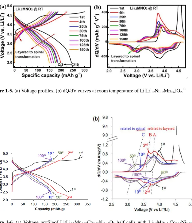
Figure 1-5. (a) Voltage profiles, (d) dQ/dV curves at room temperature of Li[Li0.2Ni0.2Mn0.6]O2.
Figure 1-6. (a) Voltage profilesof Li/Li1.2Mn0.54Co0.13Ni0.13O2 half cells with Li1.2Mn0.54Co0.13Ni0.13O2
prepared at 1000℃. (b) Corresponding dQ/dV curve.
Figure 1-7. Schematics of transformation from the layered to the cubic rock-salt structure during the cycling.
10
Figure 2-1.High resolution TOF-SIMS results of cycled Al2O3-coated Li[Li0.05Ni0.4Co0.15Mn0.4]O2
electrode at 60℃.
Figure 2-2. Possible reaction mechanisms for Al2O3 converted to AlF3 with a trace of HF in
electrolyte.
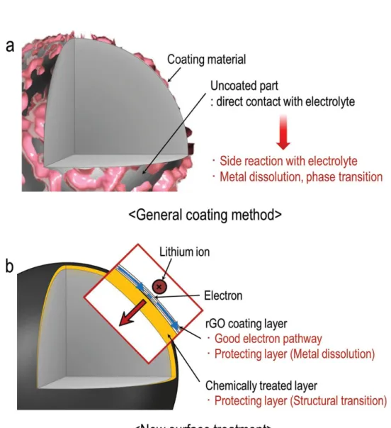
Figure 2-3.Schematics of (a) coated surface morphologies prepared from general sol-gel method, and (b) constructing hybrid surface layers consisting of rGO and chemical activation layer.
Figure 2-4. Scheme of the functioning mechanism of TPFPB. (a) Thick surface film formation in baseline electrolyte; (b) thin surface film formation in TPFPB added electrolyte.
Figure 2-5. Schematic of the formation of LiBOB-derived surface film on the cathode.
Figure 2-6. Voltage profiles of Li1.17Ni0.17Mn0.5Co0.17O2 cathodes during (a) first conditioning cycle in
a voltage range between 2.0 and 4.8 V and (b) second conditioning cycle in a voltage range between 2.0 and 4.6 V at a rate of C/10.
Figure 2-7. C 1s and O 1s XPS spectra of Li1.17Ni0.17Mn0.5Co0.17O2 cathodes after the first
conditioning cycle in electrolytes with and without 1% LiBOB.
Figure 2-8. P 2p and F 1s XPS spectra of Li1.17Ni0.17Mn0.5Co0.17O2 cathodes after the first conditioning
cycle in electrolytes with and without 1% LiBOB.
Figure 2-9.DSC heating curves of delithiated Li1.17-xNi0.17Mn0.5Co0.17O2cathodes charged up to 4.6V
after the first conditioning cycle.
Figure 2-10. Electrochemical performance of Li1.17Ni0.17Mn0.5Co0.17O2 cathodes at 30℃: (a) cycling
stability when cycled between 2.5 and 4.6 V at a rate of C/2, (b) Coulombic efficiency when cycled between 2.5 and 4.6 V at a rate of C/2 in the Ref and LiBOB-added electrolyte, (c) AC impedance spectra of Li1.17Ni0.17Mn0.5Co0.17O2 cathodes after 100
cycles in electrolytes with and without 1% LiBOB.
Figure 2-11. Comparison of the average voltage of cycled Li1.17Ni0.17Mn0.5Co0.17O2 cathodes at 30℃.
Figure 2-12. Rate capability of Li1.17Ni0.17Mn0.5Co0.17O2 cathodes at different C rates.
Figure 2-13. SEM images of Li1.17Ni0.17Mn0.5Co0.17O2 cathodes before cycling, after the first
11
30℃.
Figure 2-14. Co 2p, O 1s, and F 1s XPS spectra of Li1.17Ni0.17Mn0.5Co0.17O2 cathodes after 100 cycles
in electrolytes with and without 1% LiBOB at 30℃.
Figure 2-15. Schematic drawing for proposed functions of LiBOB-derived SEI.
Figure 2-16. Electrochemical performance of Li1.17Ni0.17Mn0.5Co0.17O2 cathodes at 60℃: (a) cycling
stability, (b) Coulombic efficiency when cycled between 2.5 and 4.6 V at a rate of C/2 in the Ref and LiBOB-added electrolyte.
Figure 2-17. Discharge capacity retention of graphite/Li1.17Ni0.17Mn0.5Co0.17O2 full cells when cycled
between 2.5 and 4.6 V at a rate of C/2.
Figure 2-18. (a) Voltage profiles of graphite/Li1.17Ni0.17Mn0.5Co0.17O2 full cells during after the first
conditioning cycle between 2.0 and 4.8 V and when charged up to 4.6 V with a constant current (CC) rate of C/10 followed by a constant voltage (CV) condition, (b) OCV variations of graphite/Li1.17Ni0.17Mn0.5Co0.17O2 full cells that were charged in electrolytes
12
List of table
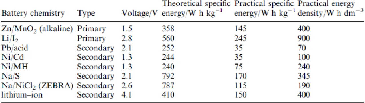
Table 1.Properties for the various battery systems.
Table 2.Properties of various cathode materials
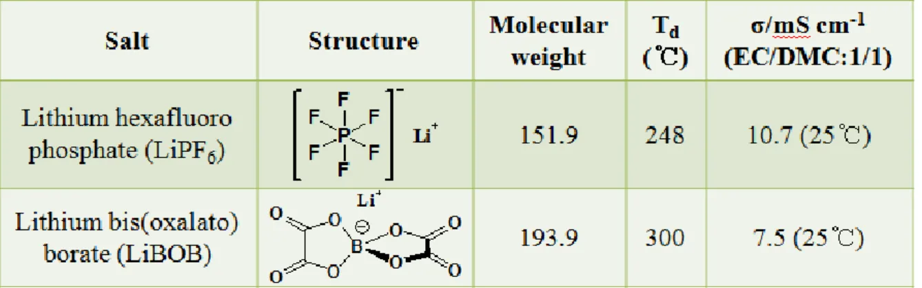
Table 3. Properties of lithium salt used in experiment.
13
CHAPTER I
1. Introduction
1.1. Lithium ion battery
Lithium ion battery is energy storage system that transforms saved chemical energy into electric energy. Lithium ion battery have a high energy density compared to different batteries (Table 1).1 Operating mechanism of lithium ion battery is based on oxidation/reduction reaction of lithium cation on the anode and cathode. Because lithium has most small molecular weight except for hydrogen, lithium can deliver high specific capacity and energy density. Therefore, lithium ion battery have served as power sources for a number of portable device. However lithium ion battery still has many problems of practical capacity related to battery components.
Now, commercialized lithium ion battery was composed of lithium cobalt oxide cathode, graphite anode, electrolyte, and PE separator (Fig 1-1). Many efforts have been conducted to overcome this limitation. Silicon active material have been mainly researched to replace graphite anode material having a small specific capacity (372mAh g-1). Silicon anode materialsdeliver a high theoretical specific capacity (3580 mAh g-1) compared to graphite anode. However, silicon anode has a relatively high operating voltage about 0.3 V vs. Li/Li+ compared to graphite (0.1 V vs. Li/Li+) anode and suffers large volume expansion (about 400%) of active material compared to graphite (about 10%) anode.2 Because of this severe problem, silicon active material have been only partially applied to practical anode of lithium ion batteries.
Lithium cobalt oxide cathode material have a specific capacity of 274 mAh g-1 but the practical capacity is only about 145 mAh g-1.3 Excess lithium extraction from lithium cobalt oxide reduce structural stability and then release oxygen. So the practical capacity of lithium cobalt oxide is comparatively limited. Many cathode material have been researched to get a high practical capacity and energy density. Lithium nickel cobalt manganese oxide (NCM), lithium nickel cobalt aluminum oxide (NCA), over-lithiated layered oxide (OLO) cathode materials have been improved. Under the condition of the charging up to high voltage, these cathode active materials are able to have the more high capacity and energy density. Despite the need for high voltage state, electrochemical stable window of electrolyte doesn’t reach proper voltage. So the studies in electrolyte have to be continuously conducted to meet surface stability of cathode at high voltage.
14
Table 1. Properties for the various battery systems.1
Figure 1-1. Graphene/LiMO2 lithium ion battery system during the discharge. 4
15
1.2. Cathode active materials of lithium ion battery
Recently, lithium ion batteries have been utilized for many portable devices such as cellular phone, digital camera, laptop computer, and tablet PC. In addition, lithium ion batteries are investigated in application in electric vehicles and energy storage system. But this applications need high energy density, long-term cycling stability, cost competitiveness, and safety. Now, lithium ion battery consisting of graphite anode, lithium cobalt oxide (LCO), PE separator and organic electrolyte present limitation of capacity and price competitiveness.
The cathode material component of Li-ion battery is partially responsible for this limitation of capacity and price competitiveness. The lithium cobalt oxide of cathode material has theoretical specific capacity of 276 mAh g-1 but the commercialized lithium cobalt oxide material has practical capacity is approximately 145 mAh g-1. This reason that practical capacity is about half of theoretical specific capacity is unstable state of delithiated Li1-xCoO2 cathode. The lithium cation in lithium
cobalt oxide is reversible for insertion/deinsertion when charge up to 4.2-4.3 V vs. Li/Li+ (x≤0.5).3 Because price of cobalt metal of lithium cobalt oxide is high, the lithium nickel cobalt manganese oxide (LiNi1/3Co1/3Mn1/3O2, stoichiometric NCM, 333 NCM) was investigated. Even though lithium
nickel cobalt manganese oxide show a reversible specific capacity of 150 mAh g-1 with potential window between 2.5 and 4.3 V vs. Li/Li+, the working voltage of Lithium nickel cobalt manganese oxide is lower than working voltage of lithium cobalt oxide. When charge cut-off voltage increases above 4.5 V, a reversible specific capacity of lithium nickel cobalt manganese oxide can increase in 200 mAh g-1.3 However, since the condition with 4.5 V vs. Li/Li+ negatively affect reversibility of phase on cathode material and interface between cathode electrode and electrolyte, it is not easy to use high cut-off voltage.
Over-lithiated layered oxide (Lithium-rich cathode) materials are investigated by many researchers. Li1+x(M)1-xO2 composed with xLi2MnO3·(1-x)LiMO2 (M = Ni, Mn, Co) is promising candidates for an
improvement in the energy of LIBs. Over-lithiated layered oxide cathode materials can deliver a discharge capacity above 200 mAh g-1 under the conditions of charging above 4.5 V vs. Li/Li+. but oxidative decomposition of electrolytes happening above 4.5 V vs. Li/Li+ is inevitable.5
16
17
2. Over-lithiated layered oxide (OLO) cathode materials 2.1. Introduction
Over-lithiated layered oxide materials composed of LiMO2 (M = Ni, Co, and Mn) and Li2MnO3
component is layered-layered structure. The LiMO2 component is electrochemically active and deliver
capacity between 2.0 and 4.5 V.
LiNi1/3Co1/3Mn1/3O2 Li +
+ e- + Ni1/3Co1/3Mn1/3O2
The lithium ion consumption of the delithiated LiMO2 component during charge up to 4.5 V was
replaced by diffusion of lithium ion from octahedral sites in the manganese layer of the Li2MnO3
component to tetrahedral sites.6 In addition to this supply of Li cation, the electrochemically inactive property of Li2MnO3 component improves structural stability of over-lithiated layered oxide materials
under the condition of charging up to 4.5 V vs. Li/Li+. The reason that the Li2MnO3 component with
tetravalent manganese cation and monovalent lithium cation is inactive under 4.5 V is that it is not easy for tetravalent manganese cation to oxidize during the charging process. So, instead of increase in oxidation number of tetravalent manganese cation, the divalent oxygen anion oxidize and release of oxygen happen.
One Li2MnO3 unit can deliver two Li cation but this reverse reaction is not possible. Because only
one Li cation can insert into MnO2 structure, the large amount of initial irreversible capacity is
inevitable. However, surplus Li cation can be expected to be provided in anode materials undergoing the initial irreversible reaction. Providing surplus lithium cation offset irreversible capacity loss of the anode and maintain capacity of full cell.
18
Figure 1-2.Phase diagram for explanation of the electrochemical reaction pathways of over-lithiatedlayered oxide cathode.5
Figure 1-3. Schematic illustration showing the 2-D spinel-like configuration in a delithiated Li2MnO3-like region of a xLi2MnO3·(1-x)LiMO2 electrode structure (M = Mn, Ni, Co).
19
2.2. Problems of over-lithiated layered oxide cathode materials 2.2.1. Effect of temperature and current density
The operating temperature and the current density during the cycle are expected that it is very important factor to influence the degree of Li2MnO3 activation and the reversible capacity is utilized.
As seen Fig 1-4(b), three respective cells were charged at the same rate of (1/20)C at room temperature, and then discharged at variousC rates of 0.1, 0.05, and 0.25 C, respectively.7 The low C rate (current density) and high temperature raise the reversible discharge capacity. Maybe, the condition with low discharge C rate cause decreasing polarization. Because this decrease of polarization delay reaching the cut-off voltage, the discharge capacity naturally increase. Besides current dinsity effect on the reversible capacity, temperature is also sensitive factor that impacts change of the capacity. The rising temperature act as a sort of the catalyst to make reaction of electrochemically inactive Li2MnO3 component easy.
20
Figure 1-4. (a) Voltage profiles of the Li/Li1.2Ni0.13Co0.13Mn0.54O2 cells (first cycle) in 1M LiPF6
(EC/DMC) at a rate of 0.05 C. (b) Voltage profiles of the Li/Li1.2Ni0.13Co0.13Mn0.54O2
21
2.2.2. Voltage fading by phase transformation
To reach a high discharge capacity, over-lithiated layered oxide cathode has to be charged up to above 4.6 V, to activate the Li2MnO3 component. The elimination of lithium cations and the
concomitant oxygen release lead to the structural instability of the cathode and a phase transformation from layered to spinel structure. Reliable evidence for the phase transformation from layered to spinel has been researched with STEM by Gu et al.8 and Xu et al.9 Therefore, dQ/dV peak intensity meaning the spinel-like structure in 3.0 V region grow and dQ/dV peak intensity meaning the layered structure in 3.7 V and 4.2 V decline (Fig 1-5, 1-6).10,11
In general, this phase transformation from layered to spinel is related to migration of transition metal ions into Li sites and Li ions into the tetrahedral sites after activation of Li2MnO3 component
with a concomitant distortion of oxygen layer.12Obvious evidence for the formation of spinel-like phase on the cycled cathode surface has been researched for cycled Li[Li0.2Ni0.2Mn0.6]O2 material at
high voltage.9 As researched, with the extensive elimination of lithium cations at high voltage, the migration of the transition metal cations into the Li site is energetically favorable at high voltage and thus could facilitate the formation of spinel-like structure.
Most recently, long-term cycling of over-lithiated layered oxide cathode has also been demonstrated to extend the LiMn2O4-type spinel formation from the surface region to the interior of
the particle.8 The phase transformation from layered to spinel is regarded as one of the main factors responsible for the voltage decay of over-lithiated layered oxide cathode. The voltage decay of the cycled cell can be directly correlated with the phase transformation from layered to spinel. However, the phase transformation from layered to spinel could not mean the continuous capacity fading because AlF3-coated over-lithiated layered oxide cathode material could accomplish considerably
improved cycling performance even though the phase transformation from layered to spinel still happen.13
22
Figure 1-5. (a) Voltage profiles, (b) dQ/dV curves at room temperature of Li[Li0.2Ni0.2Mn0.6]O2. 10
Figure 1-6. (a) Voltage profileof Li/Li1.2Mn0.54Co0.13Ni0.13O2 half cells with Li1.2Mn0.54Co0.13Ni0.13O2
23
2.2.3. Capacity fading under the condition of high voltage
There are two factors to cause the capacity fading. One is side reaction with electrolyte and cathode at high voltage. Because of getting the high capacity energy and density, over-lithiated layered oxide cathode with Li2MnO3 component has to be charged up to more high voltage with concomitant
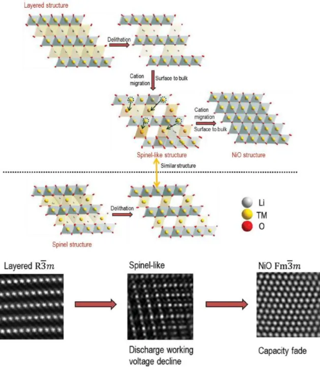
oxidative electrolyte decomposition above 4.4 V vs. Li/Li+. In order to use a high capacity over 200mAh g-1, charge cut-off voltage was selected to above 4.6 V. the cycled over-lithiated layered oxide cathode with layered and spinel structure suffer the capacity fading at high voltage. As reported by Robertson and Bruce,14 in addition to hydrolysis of electrolytes with a trace amount of water, the oxidation of the alkyl carbonates would also lead to the generation of H+ and thus resulted in increase of acidity of the electrolyte. Oxidation of electrolytes at high voltage and the attack of acidic species (HF) would lead to degradation of cathode-electrolyte interface on the cathode and result in aggravated electrochemical performance of the cathode on long-term cycling. The other factor to cause the capacity fading is structural collapse extending from the surface, with poor effects on the continuous cycling capability. The capacity fading is associated with the further phase transformations from layered to NiO phase propagating from surface to the interior of the particle (Fig 1-7).15 Reversible reaction of Li insertion/deinsertion can hardly happen on NiO phase.
24
Figure 1-7. Schematics of transformation from the layered to the cubic rock-salt structure during the cycling.15
25
CHAPTER II
Additive for improving electrochemical performances of
over-lithiated layered oxide cathode in lithium ion batteries
1. Introduction 1.1. Research trend
Over-lithiated layered oxide is prospective cathode materials because of possibility of the relatively high capacity and energy density. However over-lithiated layered oxide cathode materials still has many problems such as temperature sensitivity, high resistance, voltage decay, and capacity fading. Many efforts for over-lithiated layered oxide cathode materials are attempted to attenuate these problems.
Surface modification of cathode materials has also been knownfor a facile and beneficial methode to improve the electrochemical performance of cathode when they are charged up to high voltage. Al(OH)3-coated Li[Li0.2Ni0.2Mn0.6]O2 material has been researched to have a better rate capability and
thermal stability compared to the pristine material. In addition to Al(OH)3-coated Li[Li0.2Ni0.2Mn0.6
-]O2 material, Al2O3-coated Li[Li0.2Mn0.54Ni0.13Co0.13]O2 and Li[Li0.1-Mn0.43Ni0.23Co0.23]O2 cathode
materials have been revealed to enhance the available discharge capacity and cycling performance .16 Myung et al.17 also confirmed that the amphoteric Al2O3 coating layer with HF from electrolyte
make surface layer composed of AlF3component by time of flight-secondary-ion mass spectrometry
(TOF-SIMS) (Fig 2-1). However, the amphoteric Al2O3 coating layer will progressively convert to
AlF3 via an intermediated stage after continuous cycling, suggesting that the amphoteric Al2O3 coating
26
Figure 2-1.High resolution TOF-SIMS results of cycled Al2O3-coated Li[Li0.05Ni0.4Co0.15Mn0.4]O2
electrode at 60℃.17
Figure 2-2. Possible reaction mechanisms for Al2O3 converted to AlF3 with a trace of HF in
27
Therefore, AlF3-coated over-lithiated layered oxide cathode materials has been researched to be a
endurable coating material to stabilize surface of pristine materials. The AlF3-coated LiCoO2, 18
LiNi0.8Co0.1Mn0.1O2, 19
LiNi1/3Co1/3Mn1/3O2 20
all indicated improved electrochemical performance compared to pristine materials. AlF3-coated Li[Li0.2Mn0.54Ni0.13Co0.13]O2 sample indicated ameliorated
electrochemical performance such as loss of initial irreversible capacity, cycling performance, and rate capability.21
28
Recently, interesting surface modification of cathode materials has been introduced.This surface modification using reduced graphene oxide (rGO) coating and the chemical activation with hydrazine. The thin reduced graphene oxide layer serve as sustainable electron pathways improving surface electronic conductivity22 and protective layer suppressing metal dissolution on the cathode. And the chemical activation using the hydrazine improve initial low Coulombic efficiency and discharge voltage fading by stabilizing Li2MnO3 component on the surface.
29
Figure 2-3.Schematics of (a) coated surface morphologies prepared from general sol-gel method, and (b) constructing hybrid surface layers consisting of rGO and chemical activationlayer.15
30
Using the additive in electrolyte is easy to improve the electrochemical performance of over-lithiated layer oxide cathode materials because of the simple method. Recently, tris(pentafluoro-phenyl)borane ((C6F5)3B, TPFPB) has been reported to improve the long-term cycling performance
and formed the relatively thin passivation layer compared to baseline electrolyte on the surface of cycled Li[Li0.2Ni0.2Mn0.6]O2.
23
TPFPB act as anion receptor dissolving the byproducts such as LiF and Li2O and trapping the released oxygen species such as oxygen anions (O2
2-/O2
-) and radicals(O2●-,O●-)
attacking the electrolyte. Therefore, TPFPB additive suppresses the side reaction and maintains the thin surface.
31
Figure 2-4. Scheme of the functioning mechanism of TPFPB. (a) Thick surface film formation in baseline electrolyte; (b) thinsurface film formation in TPFPB added electrolyte.23
32
Recently, Lithium bis(oxalato)borate (LiBOB) additive was also investigated to form stable surface film and serve as a sort of anion receptor on the high voltage LiNi0.5Mn1.5O4 cathode.The LiBOB was
proven to decompose that on cathode surface by measuring linear sweep voltammetry (LSV).24 Besides, the LiBOB-derived SEI layer was confirmed to have a low leakage current compared to the reference electrolyte.
33
34
1.2. Research objective
In this study, we apply lithium bis(oxalato)borate additive in electrolyte to Li/Li1.17Ni0.17Mn0.5Co0.17
-O2 half cells and graphite/Li1.17Ni0.17Mn0.5Co0.17O2 full cells. Ha et al.24 reported that Previous reported
that LiBOB additive forms the durable surface film on the cathode and improve electrochemical cycling performance on the high voltage cathode. We confirmed LiBOB-derived surface film on the cathode by conducting X-ray photoelectron spectroscopy (XPS). Electrochemical performance of the LiBOB-derived SEI layer was confirmed by cycling coin cell test. Improved surface stability of high voltage cathode was confirmed by conducting electrochemical impedance spectroscopy (EIS) and scanning electron microscopy (SEM).
35
2. Experiment
2.1. Preparation of electrolyte and electrode
The electrolyte with and without 1 wt% lithium bis(oxalato)borate (LiBOB, Soulbrain Co. Ltd.) was composed of available 1.3 M lithium hexafluorophosphate (LiPF6, Soulbrain Co. Ltd.) dissolved
in a solvent mixture of ethylene carbonate (EC), ethylmethyl carbonate (EMC), and dimethyl carbonate (DMC) at a 3:4:3 volume ratio.
A slurry was prepared by mixing 80wt% Li1.17Ni0.17Mn0.5Co0.17O2 (0.5Li[Li1/3Mn2/3]O2·
0.5LiNi1/3Co1/3Mn1/3O2) particles (Samsung Fine Chemicals Co. Ltd.), 10 wt% carbon black as the
conducting material, and 10 wt% polyvinylidene fluoride (PVDF) binder dissolved in anhydrous N -methyl-2-pyrrolidinone (NMP, anhydrous, 99.5%, Sigma-Aldrich). The resulting slurry was cast on aluminum foil. The composite cathode was then dried in a convection oven at 110℃ for 30 min. The electrode was next pressed to a thickness of approximately 45 μm. The specific capacity of the cathode and the active material loading were 0.994 mAh cm−2 and 4.97 mg cm−2, respectively. The composite cathodes were dried in vacuum at 110℃ for at 2 hrs prior to their assembly into cells.
36
Table 3. Properties of lithium salt used in experiment.
37
2.2. Electrochemical coin cell test
A coin-type half cell (2032) with a Li1.17Ni0.17Mn0.5Co0.17O2 cathode and a Li metal electrode was
assembled in an argon-filled glove box. The thickness and porosity of the microporous polyethylene film (PE, SK innovation Co. Ltd.) used as the separator were 20 μm and 38%, respectively. The coin-type half cells were galvanostatically cycled at various rates and voltage windows at 30℃ using a computer-controlled battery measurement system (WonATech WBCS 3000). For the conditioning cycle, the first cycle was performed at a rate of C/10 between 2.0 V and 4.8 V followed by a second cycling at a rate of C/10 between 2.0 V and 4.6 V. Thereafter, the charge and discharge cycling for the half cells were performed at a rate of C/2 between 2.5 V and 4.6 V at 30℃ and 60℃. To investigate the high-temperature storage performances, graphite/Li1.17Ni0.17Mn0.5Co0.17O2 full cells were
galvanostatically cycled once between 2.0 V and 4.8 V at a rate of C/10 at 30℃ using a computer-controlled battery measurement system (WonATech WBCS 3000). Then, the cells were charged up to 4.6 V with a constant current (CC) rate of C/10 followed by a constant voltage (CV) condition at 30℃ and then stored at 60℃.
38
2.3. Analysis
Cell impedances of half cells were measured by means of an AC impedance analysis with an IVIUM frequency response analyzer over a frequency range of 10 mHz to 1 MHz.
After the cycling test, the coin cells were guardedly opened in the glove box to regain their electrodes for surface analyses. The electrodes were then dipped in dimethyl carbonate to detach the residual LiPF6-based electrolyte, and the resulting electodes were dried at room temperature. The
surface morphology of the electrodes was examined using a field-emission scanning electron microscope (FE-SEM; JEOL JSM-6700F). Ex-situ X-ray photoelectron spectroscopy (XPS, Thermo Scientific K-Alpha system) measurements on the dried electrodes were performed with Al Kα(hν= 1486.6 eV) radiation under ultrahigh vacuum. XPS spectra were acquired using a 0.10 eV step and 50 eV pass energy. The samples were prepared in a glove box and sealed with an aluminum pouch film before use. The prepared samples were rapidly transferred into a chamber of the instrument to minimize any possible contamination. All the XPS spectra were energy calibrated by the hydrocarbon peak at the binding energy of 285 eV.
To measure the thermal properties of the delithiated cathodes, coin half-cells were charged up to 4.6 V after the first conditioning cycle. Then, the half-cells were carefully opened in a dry room, and the retrieved cathodes were rinsed. The resulting cathodes were dried and transferred intact into a high-pressure stainless steel pan to preserve the products. Thermal analysis of the cycled Li1.17Ni0.17Mn0.5Co0.17O2 cathodes was conducted using differential scanning calorimetry (DSC1,
Mettler Toledo). Each sample was heated at a rate of 5℃ min−1 over 50℃-330℃ under a nitrogen atmosphere. The amount of entrapped electrolyte was 50 wt% based on the electrode sample.
39
3. Results and discussion
3.1. Electrochemical cell test and surface analysis for conditioning cycle of Li/Li1.17Ni0.17Mn0.5
-Co0.17O2 cells
Figure 2-6 presents the voltage profiles of the Li/Li1.17Ni0.17Mn0.5Co0.17O2 half cells with and
without 1% lithium bis(oxalato)borate (LiBOB) during the first and the second conditioning cycle at 30℃. The Li1.17Ni0.17Mn0.5Co0.17O2 cathodes with the LiBOB-added electrolyte exhibited slightly
reduced charge and discharge capacity of 322.7 mAh g−1 and 285.3 mAh g−1 with an initial Coulombic efficiency (ICE) of 88.4% compared with the reference electrolyte, which delivered charge and discharge capacity of 323.1 mAh g−1 and 296.5 mAh g−1 with an ICE of 91.8% in the first conditioning cycle. For the first conditioning cycle, the Li1.17Ni0.17Mn0.5Co0.17O2 cathodes in the
LiBOB-added electrolyte delivered slightly reduced charge capacity, discharge capacity (0.1% and 3.8%), and ICE (3.4%), as presented in Fig 2-6a. This finding is most likely due to the LiBOB additive undergoing the surface-filming process and consuming the Li+source. For the second conditioning cycle, the Li1.17Ni0.17Mn0.5Co0.17O2 cathode with 1% LiBOB exhibited an improved
reversible capacity (Fig 2-6b). This result indicates that LiBOB as an additive decomposes on the cathode surface during the conditioning cycle between 2.0 V and 4.8 V, and the resulting LiBOB-originated surface film is effective in improving the reversible electrochemical reactions of the cathode. This beneficial effect of the LiBOB additive on the electrochemical performance of the Li1.17Ni0.17Mn0.5Co0.17O2 cathode is similar to previous reports that LiBOB forms a protective layer on
40
Figure 2-6. Voltage profiles of Li1.17Ni0.17Mn0.5Co0.17O2 cathodes during (a) first conditioning cycle in
a voltage range between 2.0 and 4.8 V and (b) second conditioning cycle in a voltage range between 2.0 and 4.6 V at a rate of C/10.
41
The formation of LiBOB-derived SEI on the Li1.17Ni0.17Mn0.5Co0.17O2cathode was confirmed by
comparison of the XPS spectra for the cathodes in the reference and the LiBOB-added electrolyte. In both cases, the cells were applied only for the first conditioning cycle. A noticeable feature for the cathode in the LiBOB-added electrolyte is the increase in the peak intensity attributed to the semicarbonate-like species (–CO2–) at 288.8 eV, as observed in Fig 2-7. This result is most likely due
to the SEI layer formed by the oxidative decomposition of the LiBOB additive containing semicarbonate-like species and covering the cathode surface. LiBOB, which makes the surface film with carbonyl-rich species (semicarbonate-like compounds) on a graphite anode, have been identified as one of very effective reducible additives.27Recently, it was reported that LiBOB can form the SEI on the high-voltage cathode and the LiBOB-derived SEI contains semicarbonate-like species.28,24
It is worthy to note that the detailed structure and formation mechanisms of the SEI layers formed by reduction and oxidation of LiBOB are different.28,27Further evidence for the LiBOB-originated SEI is given by comparison of the carboxylate/carbonate (C=O) peak of the O 1s XPS spectra. The O 1s spectra for the Li1.17Ni0.17Mn0.5Co0.17O2cathode surface in the LiBOB-added electrolyte clearly
exhibits a more pronounced peak corresponding to C=O at 531.8 eV. This result means that the oxygen in the LiBOB-derived SEI is relatively abundant.24The decomposition products formed on the cathode in the reference electrolyte and LiBOB-added electrolyte are identified in the P 2p and F 1s XPS spectra of Fig 2-8. For the cathode in the reference electrolyte, a peak corresponding to the LixPOyFz species clearly appeared at approximately 135 eV in the P 2p XPS of Fig. 5. However, the
LixPOyFz species at 135 eV drastically decrease for the cathode in the LiBOB-added electrolyte
compared with the C-O-C peak intensity observed in the C 1s spectra of Fig 2-7.26, 29As clearly seen in the F 1s spectra of Fig 2-8, the SEI formed on a cathode with the reference electrolyte is composed of a relatively large fraction of LiF compared with the C-O-C peak intensity in the C 1s spectra of Fig 2-7. On the other hand, the C 1s and F 1s XPS spectra of Figs. 2-7 and 2-8 show that the LiF peak is not much stronger than that of the C-O-C peak intensity for the surface film of the cathode precycled in the LiBOB-added electrolyte. This finding indicates that the LiBOB-derived SEI remarkably restrains the formation of LiF and several possible fluorine compounds via electrochemical decomposition of PF5 and PF6−in the electrolyte.
42
Figure 2-7. C 1s and O 1s XPS spectra of Li1.17Ni0.17Mn0.5Co0.17O2 cathodes after the first
conditioning cycle in electrolyte with and without 1% LiBOB.
Figure 2-8. P 2p and F 1s XPS spectra of Li1.17Ni0.17Mn0.5Co0.17O2 cathodes after the first conditioning
43
To investigate the thermal stability of delithiated cathodes, differential scanning calorimetry (DSC) measurements were performed. Figure 2-9 clearly demonstrates that the use of the LiBOB additive delays the onset temperature from 264℃ to 276℃ and reduces the exothermic heat due to the thermal decomposition reaction between the delithiated cathode and the electrolyte. The exothermic thermal reaction of the delithiated cathode with the electrolyte is known to be affected by the surface structure of the cathode particles and catalytic properties of surface metal ions such as Ni4+and Mn4+.30,31In this regard, it is possible that the LiBOB-derived SEI inhibits the exothermic reactions of the cathode via the minimization of physical contact with the electrolyte.
44
Figure 2-9.DSC heating curves of delithiated Li1.17-xNi0.17Mn0.5Co0.17O2cathodes charged up to 4.6V
45
3.2. Electrochemical cell test and surface analysis for cycling of Li/Li1.17Ni0.17Mn0.5Co0.17O2 cells
Figure 2-10a presents the discharge capacity retention of Li/Li1.17Ni0.17Mn0.5Co0.17O2 half cells with
and without 1% LiBOB during 100 cycles at 30℃. The discharge capacity retention of the Li/Li1.17Ni0.17Mn0.5Co0.17O2 half cells with 1% LiBOB was significantly improved compared with the
reference electrolyte from 70.9% to 90.8% after 100 cycles at 30℃. This result indicates that the Li- BOB additive preserves efficient electronic and ionic transport pathways at the cathode-electrolyte interface by maintaining a stable SEI. Therefore, the cathode realizes very good capacity retention during cycling.
In addition, a high Coulombic efficiency of greater than 99.5%, which is vital for practical applications, was obtained during 100 cycles. However, the Coulombic efficiency of the cathodes cycled in the reference electrolyte was very low and continuously decreased, as observed in Fig 2-10b. This electrochemical result suggests that the LiBOB-derived SEI layer effectively mitigates the continuous electrolyte decomposition at the high-voltage Li1.17Ni0.17Mn0.5Co0.17O2 cathode.
Figure 2-10c shows AC impedance spectra of Li/Li1.17Ni0.17Mn0.5Co0.17O2 half cells after 100 cycles
at 30◦C. It is apparent that the interfacial resistance of the cell with the LiBOB additive is relatively lower than that of the cathode cycled in the reference electrolyte. This result is in good agreement with the previous result that LiBOB-containing cells display low impedance after extended cycling compared to the additive-free electrolyte.28This implies that the LiBOB additive makes the protective layer on the cathode and effectively suppresses the increase of the impedance by severe electrolyte decomposition at high voltages.
46
Figure 2-10. Electrochemical performance of Li1.17Ni0.17Mn0.5Co0.17O2 cathodes at 30℃: (a) cycling
stability when cycled between 2.5 and 4.6 V at a rate of C/2, (b) Coulombic efficiency when cycled between 2.5 and 4.6 V at a rate of C/2 in the Ref and LiBOB-added electrolyte, (c) AC impedance spectra of Li1.17Ni0.17Mn0.5Co0.17O2 cathodes after 100
47
To understand the effect of LiBOB additive on the voltage decay induced by the layered-to-spinel transformation of Li1.17Ni0.17Mn0.5Co0.17O2, the change of the average voltage of cathodes with and
without LiBOB was monitored during cycling. Interestingly, relatively high average voltage for the cathode with the LiBOB-added electrolyte was maintained compared to the Ref electrolyte. Although the LiBOB additive did not completely prevent the layered-to-spinel transformation of Li1.17Ni0.17Mn0.5Co0.17O2, the irreversible voltage decay of the cathode cycled in the LiBOB-added
48
49
The cycling performance of the Li1.17Ni0.17Mn0.5Co0.17O2cathode was evaluated at various C rates to
investigate the suitability of the LiBOB-derived SEI for facilitating charge transfer at the cathode electrolyte interface, as shown in Fig 2-12. It is clear that the LiBOB-added electrolyte leads to a superior rate capability compared with the reference electrolyte. The Li1.17Ni0.17Mn0.5Co0.17O2 cathode
with the LiBOB additive delivered a discharge capacity of 115 mAh g−1at a high current density (514 mA g−1, corresponding to 2 C) at 30℃. However, the cathode in the reference electrolyte exhibited rapid capacity fading upon increasing the applied current density and delivered a discharge capacity of only 25 mAh g−1 at a rate of 2 C. This result suggests that the LiBOB-originated SEI allows fast charge transfer at high C rates, while the SEI formed by the reference electrolyte impeded the reaction.
50
51
Figure 2-13 presents SEM images of the Li1.17Ni0.17Mn0.5Co0.17O2cathodes before and after being
cycled in electrolytes with and without 1% LiBOB at 30℃. It is notable that a thick SEI layer formed by the decomposition of the reference electrolyte partially covers the cathode surface after 100 cycles, as presented in Fig 2-13a. However, the cathode surface cycled in the LiBOB-added electrolyte was relatively clean, and cathode particles were clearly observed after 100 cycles (Fig 2-13b).
52
Figure 2-13. SEM images of Li1.17Ni0.17Mn0.5Co0.17O2 cathodes before cycling, after the first
conditioning cycle, and after 100 cycles in (a) Ref, (b) LiBOB-added electrolyte at 30℃.
53
This morphological difference is further supported by the Co 2p XPS spectra of the Li1.17Ni0.17Mn0.5Co0.17O2cathodes retrieved after 100 cycles (Fig 2-14). The Co (2p1/2; 796 eV) and Co
(2p3/2; 780 eV) peak intensities corresponding to the Co element are much weaker for the cathode
cycled in the reference electrolyte. This result is attributed to the thick SEI layer formed by the decomposition of the reference electrolyte, blocking the Co signal from the cathode. This result is consistent with the SEM observation that a thick SEI layer was formed on the cathode cycled in the reference electrolyte. The cathode cycled in the LiBOB-added electrolyte exhibited a much stronger Co signal in the Co 2p XPS, as shown in Fig 2-14. Further evidence for the formation of a thin SEI layer on the cathode in the LiBOB-added electrolyte is given by the O 1s XPS spectra in Fig 2-14. The peak at approximately 529 eV, which is assigned to the metal oxide (M-O) of the cathode, was more intense for the LiBOB-containing electrolyte. Moreover, the F1s spectra reveal that the peak corresponding to the LixPOyFz and LixPFy is discernibly reduced for the cathode in the LiBOB-added
electrolyte after 100 cycles. This finding indicates that the LiBOB-derived SEI greatly suppresses the oxidative decomposition of the electrolyte.
54
Figure 2-14. Co 2p, O 1s, and F 1s XPS spectra of Li1.17Ni0.17Mn0.5Co0.17O2 cathodes after 100 cycles
55
From this result, the expected functions of the LiBOB-originated SEI are proposed, as depicted in Fig 2-15. Because the LiBOB additive may readily react with water traces to form B(C2O4)(OH) and
LiB(C2O4)(OH)2, 32
the decomposition of LiPF6 salt and the formation of HF promoting the metal ion
(Mn, Ni, Co) dissolution33, 34is expected to be suppressed. The ex situ XPS results presented in Figs 2-8 and 2-14 indicated that the formation of LiF, LixPOyFz, and LixPFy species by the salt decomposition
for the cathode with the LiBOB-added electrolyte was greatly suppressed.
The EC solvent may undergo the oxidative decomposition resulting in radical cation (EC•+),35as depicted in Fig 2-15. In addition to the inhibition of LiPF6 decomposition and HF formation, the
LiBOB-derived SEI layer on the cathode surface can be expected to have two additional positive effects, as illustrated in Fig 2-15. First, it is speculated that reduction of the oxygen (O2) gas evolved
from the activation of Li2MnO3 may occur due to the acceptance of e−during the discharge process,
and the resulting superoxide anion (O2−) 36
may be trapped by the electron-deficient boron atom in the LiBOB-originated SEI formed on the cathode surface; thus, the LiBOB-derived SEI can be expected to alleviate unwanted decomposition of electrolyte solvents by O2−attack (carbonate solvent +
O2−→linear lithium alkyl carbonate, Li2CO3). 36
Second, the presence of the LiBOB-derived SEI on the cathode can minimize the reaction between O2 and Li to form Li2O
37
during the charging process. In this regard, it is believed that the presence of the surface film produced by LiBOB decomposition positively affects the cathode surface chemistry.
56
57
The discharge capacity retention of Li/Li1.17Ni0.17Mn0.5Co0.17O2half cells with and without 1%
LiBOB at 60℃ is shown in Fig 2-16. The discharge capacities of the cathodes with and without LiBOB obtained at the first cycle were 253 mAh g−1 and 273 mAh g−1, respectively. These discharge capacities of the cathodes at 60℃ were higher than those of the cathodes at 30℃ (212 mAh g−1 for LiBOB-containing cells and 202 mAh g−1 for cells with the reference electrolyte) because the inactive Li2MnO3 component in the cathode materials becomes active and contributes to the reversible
capacity at high temperatures. Thackeray et al. clearly described that increasing the temperature makes the Li2MnO3 activation much more effective, and therefore, the lithium-rich cathode delivers a
high reversible capacity at elevated temperature.38As shown in Fig 2-16a, an excellent cycling stability of the Li1.17Ni0.17Mn0.5Co0.17O2cathode at 60℃was achieved in the LiBOB-added electrolyte,
which delivers a discharge capacity of 194 mAh g−1 without noticeable capacity loss. The discharge capacity retention was remarkably improved from 28.6% (reference electrolyte) to 77.6% (LiBOB-added electrolyte) after 100 cycles at 60℃. At elevated temperature, the capacity fading of the cathodes in the reference electrolyte was considerably poor compared with the LiBOB-added electrolyte (Fig 2-16a). Importantly, a very unstable and low coulombic efficiency, which indicates significant consumption of Li+sources, was observed for the cathode in the reference electrolyte during cycling (Fig 2-16b). This finding suggests that the LiBOB-originated SEI layer inhibits direct contact of the electrolyte components with the high-voltage Li1.17Ni0.17Mn0.5Co0.17O2cathode and, thus,
effectively suppresses the severe oxidative decomposition of the electrolyte upon prolonged cycling at 60℃.
58
Figure 2-16. Electrochemical performance of Li1.17Ni0.17Mn0.5Co0.17O2 cathodes at 60℃: (a) cycling
stability, (b) Coulombic efficiency when cycled between 2.5 and 4.6 V at a rate of C/2 in the Ref and LiBOB-added electrolyte.
59
3.3. Electrochemical cell test for cycling and storage test of graphite/Li1.17Ni0.17Mn0.5Co0.17O2 cells
Figure 2-17 shows the discharge capacity retention of full cells based on graphite anode and Li1.17Ni0.17Mn0.5Co0.17O2cathode with and without 1% LiBOB after the first conditioning cycle at 30℃.
The LiBOB-containing cell exhibited relatively improved cycling stability, compared with the reference electrolyte. This indicates that the presence of LiBOB additive effectively suppresses capacity fading of full cells during cycling.
60
Figure 2-17. Discharge capacity retention of graphite/Li1.17Ni0.17Mn0.5Co0.17O2 full cells when cycled
61
Figure 2-18a presents the voltage profiles of graphite/Li1.17Ni0.17Mn0.5Co0.17O2 full cells with and
without 1% LiBOB during the first conditioning cycle and the next charge process at 30℃. Except for the slightly higher polarization of the cell with LiBOB during the conditioning cycle, there was no significant difference between the charge and discharge capacities of the two full cells. The charge capacity of the full cell with 1% LiBOB was marginally larger than that with the reference electrolyte during the following charge process.
Figure 2-18b shows the open circuit voltage (OCV) of fully charged graphite/Li1.17Ni0.17Mn0.5Co0.17
-O2 full cells with and without the 1% LiBOB additive during storage at 60℃ for 20 days. The OCV of
the full cell without LiBOB decreased considerably from 4.22 V to 3.67 V during the early 8 days, whereas the cell with LiBOB exhibited little OCV drop. The OCV drop of the full cell without the LiBOB additive at 60℃ can be explained by the metal dissolution from the delithiated cathode. The metal (Mn, Ni, and Co) ions dissolved from the cathode by the HF attack can move toward a lithiated graphite anode when the cell is stored at a high temperature such as 60℃. Recently, our group described this point when full cells were stored and cycled at 60℃.39,40,41
These metal ions then deposit on the anode surface by taking the electrons from the lithiated graphite anode. This electron consumption via the metal reduction on the lithiated graphite anode results in an increase in the anode potential and thus a decrease in the full cell potential. For a full cell with 1% LiBOB, because the LiBOB-derived SEI formed on the cathode prevents the direct physical contact with the electrolyte, it is expected that the metal dissolution from the cathode is suppressed and that the OCV does not drop significantly. Thus, it is rational that the LiBOB-derived SEI effectively restrains the self-discharge of the fully charged cell via the metal deposit on the lithiated graphite anode.
62
Figure 2-18. (a) Voltage profiles of graphite/Li1.17Ni0.17Mn0.5Co0.17O2 full cells during after the first
conditioning cycle between 2.0 and 4.8 V and when charged up to 4.6 V with a constant current (CC) rate of C/10 followed by a constant voltage (CV) condition, (b) OCV variations of graphite/Li1.17Ni0.17Mn0.5Co0.17O2 full cells that were charged in electrolytes
63
4. Conclusion
The positive effect of the LiBOB additive on the electrochemical performance of Li1.17Ni0.17Mn0.5Co0.17O2cathodes in half- and full- cells was investigated. SEM and XPS studies
confirmed that the surface film formed on the cathode cycled in LiBOB-added electrolyte was relatively thin and effectively mitigated the electrolyte decomposition, whereas that cycled in the reference electrolyte formed a thick and unstable surface film on the lithium-rich cathode surface, which presumably originated from the significant electrolyte decomposition. Furthermore, the LiBOB-derived protective layer greatly improved the storage performance of the fully charged graphite /Li1.17Ni0.17Mn0.5Co0.17O2full cells at 60℃.
64
Reference
1.Palacin, M. R., Recent advances in rechargeable battery materials: a chemist's perspective. Chem Soc Rev 2009,38 (9), 2565-2575.
2.Chun, M. J.; Park, H.; Park, S.; Choi, N. S., Bicontinuous structured silicon anode exhibiting stable cycling performance at elevated temperature. Rsc Adv 2013,3 (44), 21320-21325.
3.Robert, R.; Villevieille, C.; Novak, P., Enhancement of the high potential specific charge in layered electrode materials for lithium-ion batteries. Journal of Materials Chemistry A 2014,2 (23), 8589-8598.
4.Li, Y.; Song, J.; Yang, J., A review on structure model and energy system design of lithium-ion battery in renewable energy vehicle. Renewable and Sustainable Energy Reviews 2014,37 (0), 627-633.
5.Thackeray, M. M.; Kang, S.-H.; Johnson, C. S.; Vaughey, J. T.; Benedek, R.; Hackney, S. A., Li2MnO3-stabilized LiMO2 (M = Mn, Ni, Co) electrodes for lithium-ion batteries. Journal of
Materials Chemistry 2007,17 (30), 3112-3125.
6.Grey, C. P.; Yoon, W.-S.; Reed, J.; Ceder, G., Electrochemical Activity of Li in the Transition-Metal Sites of O3 Li[Li( 1 − 2x )/3Mn( 2 − x )/3Nix]O2. Electrochemical and Solid-State Letters 2004,7 (9),
A290-A293.
7.Yabuuchi, N.; Yoshii, K.; Myung, S. T.; Nakai, I.; Komaba, S., Detailed Studies of a High-Capacity Electrode Material for Rechargeable Batteries, Li2MnO3-LiCo1/3Ni1/3Mn1/3O2. Journal of the
American Chemical Society 2011,133 (12), 4404-4419.
8.Gu, M.; Belharouak, I.; Zheng, J. M.; Wu, H. M.; Xiao, J.; Genc, A.; Amine, K.; Thevuthasan, S.; Baer, D. R.; Zhang, J. G.; Browning, N. D.; Liu, J.; Wang, C. M., Formation of the Spinel Phase in the Layered Composite Cathode Used in Li-Ion Batteries. Acs Nano 2013,7 (1), 760-767.
9.Xu, B.; Fell, C. R.; Chi, M. F.; Meng, Y. S., Identifying surface structural changes in layered Li-excess nickel manganese oxides in high voltage lithium ion batteries: A joint experimental and theoretical study. Energ Environ Sci 2011,4 (6), 2223-2233.
10.Zheng, J. M.; Gu, M.; Xiao, J.; Zuo, P. J.; Wang, C. M.; Zhang, J. G., Corrosion/Fragmentation of Layered Composite Cathode and Related Capacity/Voltage Fading during Cycling Process. Nano Lett 2013,13 (8), 3824-3830.
11.Koga, H.; Croguennec, L.; Menetrier, M.; Mannessiez, P.; Weill, F.; Delmas, C., Different oxygen redox participation for bulk and surface: A possible global explanation for the cycling mechanism of Li1.20Mn0.54Co0.13Ni0.13O2. Journal of Power Sources 2013,236, 250-258.
65
formation of a framework structure for Li-rich layered cathode material Li[Ni0.17Li0.2Co0.07Mn0.56]O2
upon the first charge and discharge. Journal of Power Sources 2011,196 (10), 4785-4790.
13.Wang, X. Y.; Ye, X. H.; Zhi, X. K.; He, A. Z.; Zhao, Z.; Zhang, S.; Shi, J., Effects of AlF3
Coating on the Electrochemical Performance of Li1.2Mn0.534Ni0.133Co0.133O2 Cathode Materials.
Chinese J Inorg Chem 2013,29 (4), 774-778.
14.Robertson, A. D.; Bruce, P. G., Mechanism of Electrochemical Activity in Li2MnO3. Chemistry of Materials 2003,15 (10), 1984-1992.
15.Oh, P.; Ko, M.; Myeong, S.; Kim, Y.; Cho, J., A Novel Surface Treatment Method and New Insight into Discharge Voltage Deterioration for High-Performance 0.4Li2MnO3
-0.6LiNi1/3Co1/3Mn1/3O2 Cathode Materials. Advanced Energy Materials 2014, n/a-n/a.
16.Wu, Y.; Manthiram, A., High Capacity, Surface-Modified Layered Li[Li( 1 − x )∕3Mn( 2 − x )∕3Nix∕3Co x∕3]O2 Cathodes with Low Irreversible Capacity Loss. Electrochemical and Solid-State Letters 2006,9
(5), A221-A224.
17.Myung, S.-T.; Izumi, K.; Komaba, S.; Sun, Y.-K.; Yashiro, H.; Kumagai, N., Role of Alumina Coating on Li−Ni−Co−Mn−O Particles as Positive Electrode Material for Lithium-Ion Batteries.
Chemistry of Materials 2005,17 (14), 3695-3704.
18.(a) Sun, Y. K.; Han, J. M.; Myung, S. T.; Lee, S. W.; Amine, K., Significant improvement of high voltage cycling behavior AlF3-coated LiCoO2 cathode. Electrochemistry Communications 2006,8
(5), 821-826;(b) Sun, Y. K.; Cho, S. W.; Myung, S. T.; Amine, K.; Prakash, J., Effect of AlF3 coating
amount on high voltage cycling performance of LiCoO2. Electrochim Acta 2007,53 (2), 1013-1019. 19.Woo, S.-U.; Yoon, C. S.; Amine, K.; Belharouak, I.; Sun, Y.-K., Significant Improvement of Electrochemical Performance of AlF3-Coated Li[Ni0.8Co0.1Mn0.1]O2 Cathode Materials. J Electrochem
Soc 2007,154 (11), A1005-A1009.
20.(a) Sun, Y.-K.; Cho, S.-W.; Lee, S.-W.; Yoon, C. S.; Amine, K., AlF3-Coating to Improve High
Voltage Cycling Performance of Li [ Ni1∕3Co1∕3Mn1∕3]O2 Cathode Materials for Lithium Secondary
Batteries. J Electrochem Soc 2007,154 (3), A168-A172;(b) Park, B. C.; Kim, H. B.; Myung, S. T.; Amine, K.; Belharouak, I.; Lee, S. M.; Sun, Y. K., Improvement of structural and electrochemical properties of AlF3-coated Li[Ni1/3Co1/3Mn1/3]O2 cathode materials on high voltage region. Journal of
Power Sources 2008,178 (2), 826-831.
21.Zheng, J. M.; Zhang, Z. R.; Wu, X. B.; Dong, Z. X.; Zhu, Z.; Yang, Y., The effects of AlF(3)
coating on the performance of Li[Li(0.2)Mn(0.54)Ni(0.13)Co(0.13)]O(2) positive electrode material for
lithium-ion battery. J Electrochem Soc 2008,155 (10), A775-A782.
22.Luo, J. Y.; Zhao, X.; Wu, J. S.; Jang, H. D.; Kung, H. H.; Huang, J. X., Crumpled Graphene-Encapsulated Si Nanoparticles for Lithium Ion Battery Anodes. J Phys Chem Lett 2012,3 (13), 1824-1829.
66
23.Zheng, J. M.; Xiao, J.; Gu, M.; Zuo, P. J.; Wang, C. M.; Zhang, J. G., Interface modifications by anion receptors for high energy lithium ion batteries. Journal of Power Sources 2014,250, 313-318.
24.Ha, S.-Y.; Han, J.-G.; Song, Y.-M.; Chun, M.-J.; Han, S.-I.; Shin, W.-C.; Choi, N.-S., Using a lithium bis(oxalato)borate additive to improve electrochemical performance of high-voltage spinel LiNi0.5Mn1.5O4 cathodes at 60°C. Electrochim Acta 2013,104 (0), 170-177.
25.Pieczonka, N. P. W.; Yang, L.; Balogh, M. P.; Powell, B. R.; Chemelewski, K.; Manthiram, A.; Krachkovskiy, S. A.; Goward, G. R.; Liu, M. H.; Kim, J. H., Impact of Lithium Bis(oxalate)borate Electrolyte Additive on the Performance of High-Voltage Spinel/Graphite Li-Ion Batteries. J Phys Chem C 2013,117 (44), 22603-22612.
26.Yang, L.; Markmaitree, T.; Lucht, B. L., Inorganic additives for passivation of high voltage cathode materials. Journal of Power Sources 2011,196 (4), 2251-2254.
27.Xu, K.; Lee, U.; Zhang, S. S.; Wood, M.; Jow, T. R., Chemical analysis of graphite/electrolyte interface formed in LiBOB-based electrolytes. Electrochem Solid St 2003,6 (7), A144-A148.
28.Zhu, Y.; Li, Y.; Bettge, M.; Abraham, D. P., Electrolyte additive combinations that enhance performance of high-capacity Li1.2Ni0.15Mn0.55Co0.1O2-graphite cells. Electrochim Acta 2013,110,
191-199.
29.Choi, N. S.; Yew, K. H.; Lee, K. Y.; Sung, M.; Kim, H.; Kim, S. S., Effect of fluoroethylene carbonate additive on interfacial properties of silicon thin-film electrode. Journal of Power Sources 2006,161 (2), 1254-1259.
30.Kim, Y.; Eom, J.; Kim, M. G.; Sun, Y. K.; Yoon, C. S.; Cho, J. P., Comparison of structural changes in fully delithiated Lix[Ni1/3Co1/3Mn1/3]O2 and Lix[Ni0.33Co0.33Mn0.30Mg0.04]O1.96F0.04 cathodes
(x=0) upon thermal annealing. J Electrochem Soc 2007,154 (6), A561-A565.
31.Myung, S.-T.; Noh, H.-J.; Yoon, S.-J.; Lee, E.-J.; Sun, Y.-K., Progress in High-Capacity Core– Shell Cathode Materials for Rechargeable Lithium Batteries. The Journal of Physical Chemistry Letters 2014,5 (4), 671-679.
32.Yang, L.; Furczon, M. M.; Xiao, A.; Lucht, B. L.; Zhang, Z.; Abraham, D. P., Effect of impurities and moisture on lithium bisoxalatoborate (LiBOB) electrolyte performance in lithium-ion cells. Journal of Power Sources 2010,195 (6), 1698-1705.
33.Pieczonka, N. P. W.; Liu, Z.; Lu, P.; Olson, K. L.; Moote, J.; Powell, B. R.; Kim, J.-H., Understanding Transition-Metal Dissolution Behavior in LiNi0.5Mn1.5O4 High-Voltage Spinel for
Lithium Ion Batteries. The Journal of Physical Chemistry C 2013,117 (31), 15947-15957.
34.Myung, S.-T.; Amine, K.; Sun, Y.-K., Surface modification of cathode materials from nano- to microscale for rechargeable lithium-ion batteries. Journal of Materials Chemistry 2010,20 (34),
7074-67
7095.
35.Xing, L.; Li, W.; Wang, C.; Gu, F.; Xu, M.; Tan, C.; Yi, J., Theoretical Investigations on Oxidative Stability of Solvents and Oxidative Decomposition Mechanism of Ethylene Carbonate for Lithium Ion Battery Use. The Journal of Physical Chemistry B 2009,113 (52), 16596-16602.
36.Yabuuchi, N.; Yoshii, K.; Myung, S.-T.; Nakai, I.; Komaba, S., Detailed Studies of a High-Capacity Electrode Material for Rechargeable Batteries, Li2MnO3·LiCo1/3Ni1/3Mn1/3O2. Journal of the
American Chemical Society 2011,133 (12), 4404-4419.
37.Hy, S.; Felix, F.; Rick, J.; Su, W.-N.; Hwang, B. J., Direct In situ Observation of Li2O Evolution
on Li-Rich High-Capacity Cathode Material, Li[NixLi(1–2x)/3Mn(2–x)/3]O2 (0 ≤ x ≤0.5). Journal of the
American Chemical Society 2013,136 (3), 999-1007.
38.Johnson, C. S.; Li, N.; Lefief, C.; Thackeray, M. M., Anomalous capacity and cycling stability of xLi2MnO3·(1−x)LiMO2 electrodes (M=Mn, Ni, Co) in lithium batteries at 50°C. Electrochemistry
Communications 2007,9 (4), 787-795.
39.Cho, I. H.; Kim, S.-S.; Shin, S. C.; Choi, N.-S., Effect of SEI on Capacity Losses of Spinel Lithium Manganese Oxide/Graphite Batteries Stored at 60 ° C. Electrochemical and Solid-State Letters 2010,13 (11), A168-A172.
40.Song, Y.-M.; Han, J.-G.; Park, S.; Lee, K. T.; Choi, N.-S., A multifunctional phosphite-containing electrolyte for 5 V-class LiNi0.5Mn1.5O4 cathodes with superior electrochemical
performance. Journal of Materials Chemistry A 2014,2 (25), 9506-9513.
41.Lee, S. J.; Han, J.-G.; Lee, Y.; Jeong, M.-H.; Shin, W. C.; Ue, M.; Choi, N.-S., A bi-functional lithium difluoro(oxalato)borate additive for lithium cobalt oxide/lithium nickel manganese cobalt oxide cathodes and silicon/graphite anodes in lithium-ion batteries at elevated temperatures.


![Figure 2-1.High resolution TOF-SIMS results of cycled Al 2 O 3 -coated Li[Li 0.05 Ni 0.4 Co 0.15 Mn 0.4 ]O 2](https://thumb-us.123doks.com/thumbv2/123dok_us/11109614.2998755/27.892.121.780.258.598/figure-high-resolution-tof-sims-results-cycled-coated.webp)