CROSS REFERENCE
Honeywell
Programmer Control
Cross Reference
Honeywell has provided proprietary and/or “labelled” controls to certain Original Equipment Manufacturers (OEM) at their request. Proprietary controls are available only from the OEM, while “labelled” controls can, in some instances, be purchased directly from Honeywell. Where a control is available only from the OEM, we have placed a footnote in the “Replacement Control” column. Refer questions about a particular OEM control to the particular OEM (see list below): Cleaver Brooks Div.
Aqua—Chem Inc. ATTN: Parts Manager P.O. Box 421
Milwaukee, WI 53201 414-577-2710
Lennox Industries Inc. Lennox Parts Center P.O. Box 7658 4251 121st Street Urbandale, IA 50322 515-251-4440
Gordon-Piatt Energy Group Parts Manager
C Street and Warehouse Road Winfield, KS 67156
316-221-4470 Ray Burner Co.
Engineering & Sales Dept. 401 Parr Boulevard Richmond, CA 94801 610-236-4272
Vapor Power International 661 S. County Line Road Franklin Park, IL 60131 630-694-5500
CROSS REFERENCE DATA
Page R4181 ... 3 R4127 ... 4 PM720 ... 7 BC7000 ... 10 R4140 ... 11 R4150 ... 16 7800 SERIES ... 22 FIREYE™ ... 26Ta ble 1 . HONEYWELL R418 1 PROGRAMMER C R OSS REFERENC E De vice to b e R eplac ed 7 800 Ser ie s R eplac emen t 1 P re p u rge In terl oc ks PFEP INTM Pil ot IN TR Pilo t MFEP Sp ark T erm Postpurge Modulation Volt ag e Freq uenc y Comm ent s Tim in g Ty p e Star t Running Locko ut Preignition Hi-fire Lo-fire Lo -Fi re On -Off L HL LHL PR V OP Damp R4 181A1 000 RM7 840G10 14 40 LF PR V X X X 10 X 15, 30 15 4- wire 12 0 20 8 24 0 60 R4 181A1 018 RM7 840L 101 8 60 X X X X X 10 X 15, 30 15 4- wire 12 0 20 8 24 0 60 R4 181A1 026 RM7 840G10 14 40 LF PR V X X X 10 X 15, 30 15 4- wire 12 0 20 8 24 0 60 R4 181A1 034 RM7 840L 101 8 60 X X X X X 10 X 10, 15 15 4- wire 12 0 20 8 24 0 60 R4 181A1 042 RM7 840L 101 8 60 X X X X X 10 X 10, 15 X 20 4- wire 12 0 60 R4 181A1 059 RM7 840L 101 8 55 X X X X X 7 X 10, 30 X 16 4- wire 12 0 60 1 See Conver si on Wir ing Diagr am in Mo der niz at ion W ir in g In fo rm a tio n se ctio n .
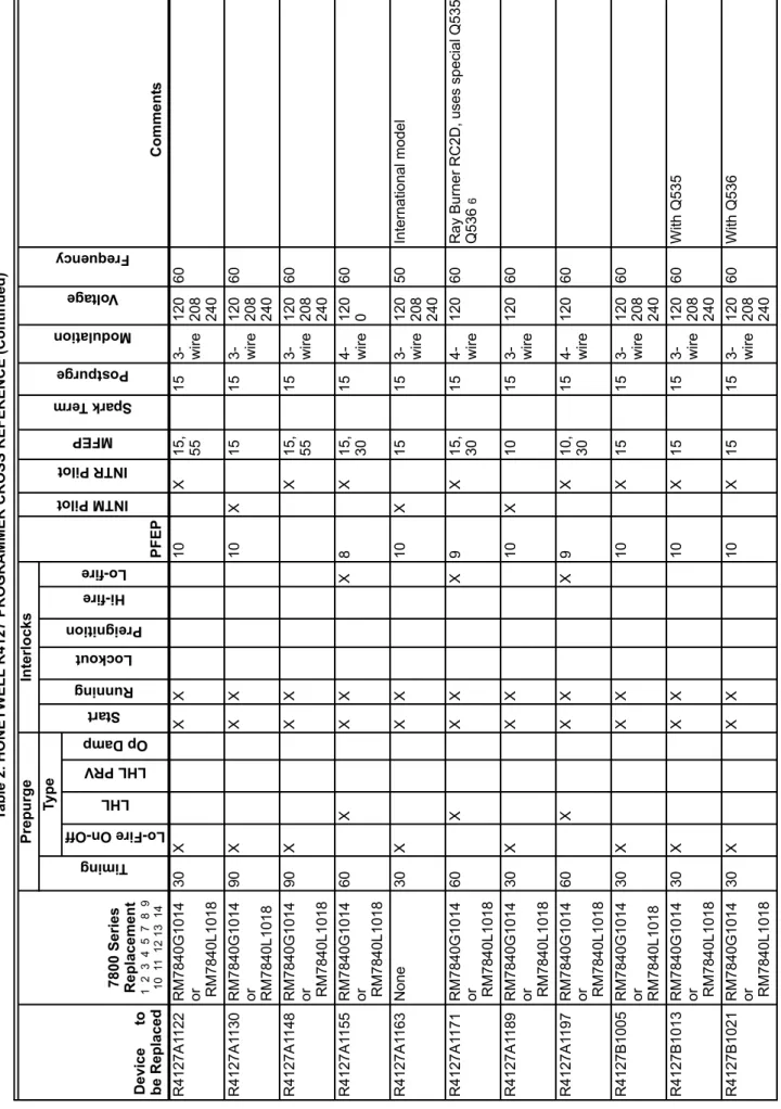
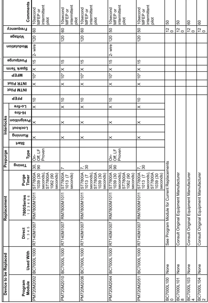
Ta ble 2. HONEYWELL R41 27 PROGRAMMER C R OSS REFEREN C E De vice to be Re pl ac ed 78 00 Series R e p la ce m en t 1 2 3 4 5 7 8 9 10 11 12 13 14 Pre p urge In te rloc ks PFEP INTM Pilo t INTR Pilo t MFEP Spar k T erm Postpurge Modulation Volt ag e Freq uenc y Comme nt s Tim in g Ty p e Star t Runn ing Lo ckout Preignition Hi-fire Lo-fire Lo-Fire On-Off LHL LHL PRV Op Da mp R4 127A1 007 RM7 840G10 14 or RM784 0L1 018 30 X X X 10 X 15 1 5 3- wire 1 20 208 240 60 W ith R 7253 A R4 127A1 015 RM7 840G10 14 or RM784 0L1 018 30 X X X 10 X 15 1 5 3- wire 1 20 208 240 60 W ith Q535 a nd R72 53A R4 127A1 023 RM7 840G10 14 or RM784 0L1 018 30 X X X 10 X 15 1 5 3- wire 1 20 208 240 60 W ith Q536 a nd R72 53A R4 127A1 031 RM7 840G10 14 or RM784 0L1 018 30 X X X 10 X 15 1 5 3- wire 1 20 208 240 60 W ith Q535 R4 127A1 049 RM7 840G10 14 or RM784 0L1 018 30 X X X 10 X 15 1 5 3- wire 1 20 208 240 60 W ith Q536 R4 127A1 056 RM7 840G10 14 or RM784 0L1 018 30 X X X 10 X 15 , 60 15 3- wire 12 0 60 R4 127A1 064 RM7 840G10 14 or RM784 0L1 018 30 X X X 10 X 15 1 5 3- wire 1 20 208 240 60 R4 127A1 072 No ne 30 X X X 10 X 15 1 5 3- wire 1 20 208 240 50 W ith Q535 in ternatio nal mode l R4 127A1 080 RM7 840G10 14 or RM784 0L1 018 30 X X X 10 X 15 , 60 15 3- wire 1 20 208 240 60 Prod uced in Ca nada R4 127A1 098 RM7 840G10 14 or RM784 0L1 018 30 X X X 10 X 15 1 5 3- wire 12 0 60 R4 127A1 106 No ne Internatio nal mode l R4 127A1 114 No ne See fo ot no te s on p ag e 6.
R4 127A1 122 RM7 840G10 14 or RM784 0L1 018 30 X X X 10 X 15 , 55 15 3- wire 1 20 208 240 60 R4 127A1 130 RM7 840G10 14 or RM7 840L 101 8 90 X X X 10 X 15 1 5 3- wire 1 20 208 240 60 R4 127A1 148 RM7 840G10 14 or RM784 0L1 018 90 X X X X 15 , 55 15 3- wire 1 20 208 240 60 R4 127A1 155 RM7 840G10 14 or RM784 0L1 018 60 X X X X 8 X 15 , 30 15 4- wire 1 20 0 60 R4 127A1 163 No ne 30 X X X 10 X 15 1 5 3- wire 1 20 208 240 50 Internatio nal mode l R4 127A1 171 RM7 840G10 14 or RM784 0L1 018 60 X X X X 9 X 15 , 30 15 4- wire 1 20 60 R a y Burne r RC2D , uses sp ecial Q535 / Q536 6 R4 127A1 189 RM7 840G10 14 or RM784 0L1 018 30 X X X 10 X 10 1 5 3- wire 12 0 60 R4 127A1 197 RM7 840G10 14 or RM784 0L1 018 60 X X X X 9 X 10 , 30 15 4- wire 12 0 60 R4 127B1 005 RM7 840G10 14 or RM7 840L 101 8 30 X X X 10 X 15 1 5 3- wire 1 20 208 240 60 R4 127B1 013 RM7 840G10 14 or RM784 0L1 018 30 X X X 10 X 15 1 5 3- wire 1 20 208 240 60 W ith Q535 R4 127B1 021 RM7 840G10 14 or RM784 0L1 018 30 X X X 10 X 15 1 5 3- wire 1 20 208 240 60 W ith Q536 Ta b le 2. HONEYWEL L R41 27 PROGRA MMER CROSS REFERENCE (Continued) De vice to be Re pl ac ed 78 00 Series R e p la ce m en t 1 2 3 4 5 7 8 9 10 11 12 13 14 Pre p urge In te rloc ks PFEP INTM Pilo t INTR Pilot MFEP Sp ark Term Postpurge Modu latio n Volt ag e Freq uenc y Comme nt s Tim in g Ty p e Star t Running Lock ou t Preign ition Hi-fire Lo-fire Lo-Fire On-Off LHL LHL PR V Op Damp See footnotes on p a ge 6.
R4 127B1 039 RM7 840G10 14 or RM784 0L1 018 30 X X X 10 X 15 1 5 3- wire 1 20 60 R a y Burne r RC 2A w ith R 7254 A, Q5 36 R4 127B1 047 RM7 840G10 14 or RM784 0L1 018 30 X X X 10 X 15 1 5 3- wire 1 20 60 R a y Burne r RC 2B w ith R 7254 A,Q535 R4 127B1 054 RM7 840G10 14 or RM784 0L1 018 30 X X X 10 X 15 1 5 3- wire 12 0 60 R ay Bu rn er R4 127C 1003 RM7 840G10 14 or RM784 0L1 018 30 X X X 10 X 15 1 5 3- wire 12 0 60 R ay Bu rn er w ith R 7 25 5 A Ta b le 2. HONEYWEL L R41 27 PROGRA MMER CROSS REFERENCE (Continued) De vice to be Re pl ac ed 78 00 Series R e p la ce m en t 1 2 3 4 5 7 8 9 10 11 12 13 14 Pre p urge In te rloc ks PFEP INTM Pilo t INTR Pilot MFEP Spark Ter m Postpurge Modu latio n Volt ag e Freque ncy Comme nt s Tim in g Ty p e Star t Running Lock ou t Preign ition Hi-fire Lo-fire Lo-Fire On-Off LHL LHL PR V Op Damp FO OTNO TES: 1 Refer to conve rs ion wi ring di ag ra ms i n M o d er n iza tio n Wir ing Inf o rm a tion s ec tion . 2 RM7840 G m eet s cur rent UL re qui re ment s. 3 RM7840 L me et s cur re nt insur a nce r e quir e me nt s. 4 See se ri es ST78 00A Plug-i n T ime rs for p repur g e ti m ings avai la ble . 5 R4127 A ,B, C S tar t Inte rl ocks becom e RM7 840 Pr ei gn it io n In ter lock s . 6 No lo nge r a v a ila bl e. 7 Repla ceme n t co ntr o ls a re 12 0 V a c, 50/ 60 Hz. 8 RM78 40G1 014 MFEP i s 1 0 , 15 , or 30 se con d s. 9 RM78 40L101 8 MFE P i s 10 or 15 se cond s. 11 S e le ct proper f lam e ampl fi er . 12 Use wi th ex is ti n g Hon eywe ll Fl am e De tector s. 13 W ith se lec tabl e ai r-flow sw it ch c h eck (AFSC). 14 W ith se lec tabl e ai r-flow sw it ch c h eck (AFSC). 15 Requires Q7 800A or Q7 800B Subbase. 10 RM78 40G1 014 and RM7 840L10 18 PFEP is 4 or 10 seconds. 1
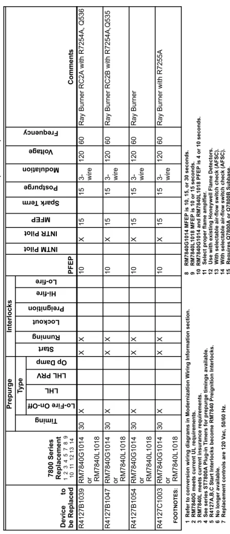
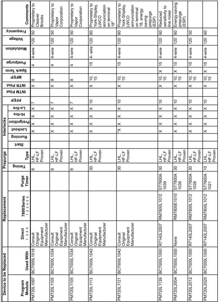
Ta ble 3. HONEYWELL BC70 00 PROGRA MMER REPLACEMENT C R OSS REFERENC E De vic e to be Re place d R eplac emen t Prep ur ge In terloc ks PFEP INTM Pilo t INTR Pilo t MFEP Spar k T erm Postpurge Modulation Volt ag e Freq uenc y Comm ent s Program Mo du le Used W it h D ir ec t 1 3 4 5 7 80 0 S er ie s 1 2 3 4 5 6 Purge Tim er Tim in g Ty p e Star t Runn ing Lo ckout Preignition Hi-fire Lo-fire PM720 G1 1 97 B C700 0L1 042 Con su lt Ori gina l Equi pment Manufacturer 40 LHL, LF Proven X X X X 10 X 1 0, 15 15 4- wire 120 6 0 Proprie ta ry to Y ork-Shi pley , LW C O an nunci ati on on termina l 18 " PM720 G1 205 BC700 0L1 042 Con su lt Ori gina l Equi pment Manufacturer 40 LHL, LF Proven X X X X 10 X 1 0, 15 15 4- wire 120 6 0 Proprie ta ry to Y ork-Shi pley , LW C O an nunci ati on on termina l 18 PM720 G2 005 BC700 0L1 000 R71 40G200 8 R M7 800 G10 18 S T 78 00A 1047 40 LHL, LF Proven XX X 10 X 1 0, 15, 30 X 15 4-wire 120 6 0 PM720 G2 013 BC700 0L1 000 R71 40G200 8 R M7 800 G10 18 S T 78 00A 1047 40 LHL, LF Proven X X X 10 X 1 0* X 15 4-wire 120 6 0 10 sec MFEP or intermitt ent pi lot PM720 G2 021 BC700 0L1 000 Con su lt Ori gina l Equi pment Manufacturer 60 LHL, LF Proven X X X 7 X 1 3* 30 4-wire 120 6 0 13 sec MFEP or intermitt ent pi lot prop riet ary to Le nnox PM720 G2 039 BC700 0L1 000 R71 40G200 8 R M7 800 G10 18 S T 78 00A 1047 40 LHL, LF Proven XX X 10 X 1 0, 15, 30 X 15 4-wire 120 5 0 PM720 L10 22 BC700 0L1 018 Con su lt Ori gina l Equi pment Manufacturer 8L H L, HF-L F Proven X X X X 7 X 8 4 4-wire 120 6 0 Proprie ta ry to Cle aver Brooks PM720 L10 30 BC700 0L1 000 R71 40L2 007 R M 7 800 L101 2 ST 78 00A 1039 30 LHL, HF-L F Proven X X X X 10 X 1 0, 15 X 15 4-wire 120 6 0 PM720 L10 63 BC700 0L1 034 Con su lt Ori gina l Equi pment Manufacturer 10 LHL, HF-L F Proven X X X X 7 X 8 4 4-wire 120 6 0 Proprie ta ry to V apo r Corp oration PM720L1089 NEVER PRODUCED See footnotes on p a ge 10.
PM720 L10 97 BC700 0L1 018 Con su lt Ori gina l Equi pment Manufacturer 8L H L, HF-L F Proven X X X X 7 X 8 4 4-wire 120 5 0 Proprie ta ry to Cle aver Brooks PM720 L1 10 5 B C700 0L1 034 Con su lt Ori gina l Equi pment Manufacturer 8L H L, HF-L F Proven X X X X 7 X 8 4 4-wire 120 5 0 Proprie ta ry to V apo r Corp oration PM720 L1 10 5 B C700 0L1 034 Con su lt Ori gina l Equi pment Manufacturer 8L H L, HF-L F Proven X X X X 7 X 8 4 4-wire 120 5 0 Proprie ta ry to V apo r Corp oration PM720 L1 11 3 B C700 0L1 042 Con su lt Ori gina l Equi pment Manufacturer 30 LHL, HF-L F Proven X X X X 10 X 1 0, 15 15 4- wire 120 6 0 Proprie ta ry to Y ork-Shi pley , LW C O an nunci ati on on termina l 18 " PM720 L1 12 1 B C700 0L1 042 Con su lt Ori gina l Equi pment Manufacturer 30 LHL, HF-L F Proven "X X X X 10 X 10 , 15 15 4-wire 120 6 0 Proprie ta ry to Y ork-Shi pley , LW C O an nunci ati on on termina l 18 , ene rgy saving prep urge (ESP) PM720 L1 13 9 B C700 0L1 000 R71 40L2 007 R M 7 800 L101 2 ST 78 00A 1039 30 LHL, HF-L F Proven X X X X 10 X 1 0, 15 X 15 4-wire 120 6 0 Red uced se ns iti vit y t o lin e noi se PM720 L20 04 BC700 0L1 000 Non e R M 7 800 E1 010 ST 78 00A 1039 30 LHL, HF-L F Proven X X X X 10 X 1 0, 15 X 15 4-wire 120 6 0 Energ y sa vi ng prep urge (ESP) PM720 L20 12 BC700 0L1 000 R71 40L2 007 R M 7 800 L101 2 ST 78 00A 1039 30 LHL, HF-L F Proven X X X X 10 X 1 0, 15 X 15 4-wire 120 5 0 PM720 L20 20 BC700 0L1 000 R71 40L2 007 R M 7 800 L101 2 ST 78 00A 1021 10 LHL, HF-L F Proven X X X X 10 X 1 0, 15 X 15 4-wire 120 6 0 Ta ble 3. HONEYWELL BC70 00 PROGRAMMER R EPLACEMENT C R OSS REFE RENC E (Continued) De vic e to be Re place d R eplac emen t Prep ur ge In terloc ks PFEP INTM Pilo t INTR Pilo t MFEP Spar k T erm Postpurge Modulation Volt ag e Freq uenc y Comm ent s Program Mo du le Used W it h D ir ec t 1 3 4 5 7 80 0 S er ie s 1 2 3 4 5 6 Purge Tim er Tim in g Ty p e Star t Runn ing Lo ckout Preignition Hi-fire Lo-fire See fo ot no te s on p ag e 10 .
PM720 M2 002 BC700 0L1 000 R71 40M100 7 R M7 800 M1 01 1 S T 78 00A 1039 (3 0 se cond s) , ST 78 00A 1062 (9 0 se cond s) 30 , 90 On -O ff, LF Proven X X X 10 X 1 0* X 15 2- wire 120 6 0 10 se cond
MFEP or intermittent pilot
PM720 M2 010 BC700 0L1 000 R71 40M100 7 R M7 800 M1 01 1 S T 78 00A 1013 (7 se cond s) 7 X X X 10 X 1 0* X 15 120 6 0 10 se cond
MFEP or intermittent pilot
PM720 M2 036 BC700 0L1 000 R71 40M100 7 R M7 800 M1 01 1 S T 78 00A 1013 (7 se cond s) , ST 78 00A 1039 (3 0 se cond s) 7, 30 X X X 10 X 1 0* X 15 120 6 0 10 se cond
MFEP or intermittent pilot
PM720 M2 044 BC700 0L1 000 R71 40M100 7 R M7 800 M1 01 1 S T 78 00A 1039 (3 0 se cond s) , ST 78 00A 1062 (9 0 se cond s) 30 , 90 On -O ff, LF Proven X X X 10 X 1 0* X 15 2- wire 120 5 0 10 se cond
MFEP or intermittent pilot
PM720 M2 051 BC700 0L1 000 R71 40M100 7 R M7 800 M1 01 1 S T 78 00A 1013 (7 se cond s) , ST 78 00A 1039 (3 0 se cond s) 7, 30 X X X 10 X 1 0* X 15 120 5 0 10 se cond
MFEP or intermittent pilot
BC70 00L 100 0 None See Progra m Modu le fo r Cu rre nt Re pla ce m ent s 12 0 50 BC70 00L 101 8 None Con su lt Origi nal Equi pment Ma nufacturer 12 0 50 BC70 00L 103 4 None Con su lt Origi nal Equi pment Ma nufacturer 12 0 60 BC70 00L 104 2 None Con su lt Origi nal Equi pment Ma nufacturer 12 0 60 Ta ble 3. HONEYWELL BC70 00 PROGRAMMER R EPLACEMENT C R OSS REFE RENC E (Continued) De vic e to be Re place d R eplac emen t Prep ur ge In terloc ks PFEP INTM Pilo t INTR Pilo t MFEP Spar k T erm Postpurge Modulation Volt ag e Freq uenc y Comm ent s Program Mo du le Used W it h D ir ec t 1 3 4 5 7 80 0 S er ie s 1 2 3 4 5 6 Purge Tim er Tim in g Ty p e Star t Runn ing Lo ckout Preignition Hi-fire Lo-fire See fo ot no te s on p ag e 10 .
FO OT NO TES: 1 4 or 1 0 se co nd PFEP . 2 Wit h S 7800 A100 1 Keyboa rd D isp lay Mo dule. 3 Sele ct prop er amplif ier : Old A m plifier: Re p la ce m e n t Am p lifie r: R72 47A1 005 R78 47A 1033 R72 47A1 021 R78 47A 1025 R72 47B1 003 R78 47B 1031 R72 47C100 1 R786 1A10 26 S ee Note 5 R72 48A1 004 R78 48A 1008 R72 48B1 028 R78 48B 1006 R72 49A1 003 R78 49A 1023 R7476 A100 7 R7 886A 1001 4 Wi th Se lect ab le Airflow Switc h Che ck. 5 Use with e xist ing f lame det ect o rs, EX CEP T C7012 E,F— Repla ce wit h C7061 A, F and a pprop riat e R7861 A m plif ier .
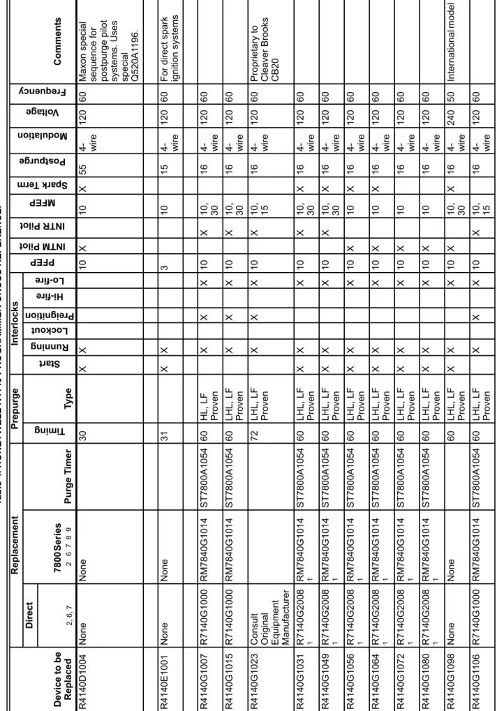
Ta ble 4. HONEYWELL R41 40 PROGRAMMER C R OSS REFEREN C E. Device to be Rep laced Rep lacem ent P rep u rg e In terloc ks PFEP INTM Pil ot IN TR Pilo t MFEP Sp ark T erm Postpurge Modulation Volt ag e Freq uenc y C o mme nt s Direct 78 00 Se ries 2 6 7 8 9 Purge T ime r Tim in g Ty p e Star t Running Lo ckout Prei gnit io n Hi-fire Lo-fire 2, 6 , 7 R4 140D 1004 N one No ne 30 X X 1 0 X 10 X 55 4- wire 12 0 6 0 M a xon speci al seque nce for postpurg e p ilo t sy stems. Uses specia l Q5 20A1 1 96. R4 140E1 001 N one No ne 31 X X 3 10 15 4- wire 12 0 6 0 F o r di re ct sp ark ignition system s R4 140G10 07 R 7140 G1 000 RM7 840G10 14 ST78 00A10 54 60 HL, LF Proven XX X 1 0 X 10 , 30 16 4- wire 12 0 6 0 R4 140G10 15 R 7140 G1 000 RM7 840G10 14 ST78 00A10 54 60 LHL , LF Proven XX X 1 0 X 10 , 30 16 4- wire 12 0 6 0 R4 140G10 23 C onsul t Origi nal Equ ipm en t Ma nufacturer 72 LHL , LF Proven XX X 1 0 X 10 , 15 16 4- wire 12 0 6 0 P ro priet ary to Clea ver Broo ks CB20 R4 140G10 31 R 7140 G2 008 1 RM7 840G10 14 1 ST78 00A10 54 60 LHL , LF Proven XX X 1 0 X 10 , 30 X1 6 4- wire 12 0 6 0 R4 140G10 49 R 7140 G2 008 1 RM7 840G10 14 1 ST78 00A10 54 60 LHL , LF Proven XX X 1 0 X 10 , 30 X1 6 4- wire 12 0 6 0 R4 140G10 56 R 7140 G2 008 1 RM7 840G10 14 1 ST78 00A10 54 60 LHL , LF Proven XX X 1 0 X 10 X 16 4- wire 12 0 6 0 R4 140G10 64 R 7140 G2 008 1 RM7 840G10 14 1 ST78 00A10 54 60 LHL , LF Proven XX X 1 0 X 10 X 16 4- wire 12 0 6 0 R4 140G10 72 R 7140 G2 008 1 RM7 840G10 14 1 ST78 00A10 54 60 LHL , LF Proven X X X 1 0 X 10 16 4- wire 12 0 6 0 R4 140G10 80 R 7140 G2 008 1 RM7 840G10 14 1 ST78 00A10 54 60 LHL , LF Proven X X X 1 0 X 10 16 4- wire 12 0 6 0 R4 140G10 98 N one No ne 60 LHL , LF Proven XX X 1 0 X 10 , 30 X1 6 4- wire 24 0 5 0 In te rn ationa l mo del R4 140G1 10 6 R 7140 G1 000 RM7 840G10 14 ST78 00A10 54 60 LHL , LF Proven XX X 1 0 X 10 , 15 16 4- wire 12 0 6 0 See footnotes on p a ge 16.
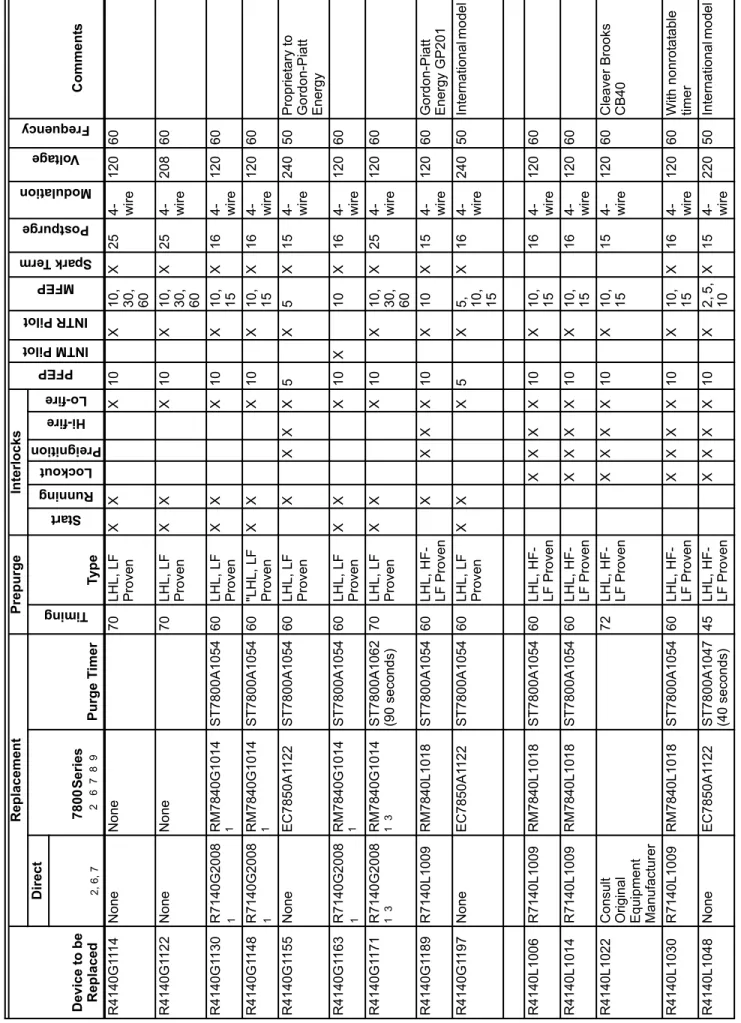
R4 140G1 11 4 N one No ne 70 LHL , LF Proven XX X 1 0 X 10 , 30 , 60 X2 5 4- wire 12 0 6 0 R4 140G1 12 2 N one No ne 70 LHL , LF Proven XX X 1 0 X 10 , 30 , 60 X2 5 4- wire 20 8 6 0 R4 140G1 13 0 R 7140 G2 008 1 RM7 840G10 14 1 ST78 00A10 54 60 LHL , LF Proven XX X 1 0 X 10 , 15 X1 6 4- wire 12 0 6 0 R4 140G1 14 8 R 7140 G2 008 1 RM7 840G10 14 1 ST78 00A10 54 60 "LH L, LF Proven XX X 1 0 X 10 , 15 X1 6 4- wire 12 0 6 0 R4 140G1 15 5 N one EC7 850 A1 122 ST78 00A10 54 60 LHL , LF Proven X X X X 5 X 5 X 15 4- wire 24 0 5 0 P ro priet ary to Go rd on-Pia tt Energy R4 140G1 16 3 R 7140 G2 008 1 RM7 840G10 14 1 ST78 00A10 54 60 LHL , LF Proven XX X 1 0 X 10 X 16 4- wire 12 0 6 0 R4 140G1 17 1 R 7140 G2 008 1 3 RM7 840G10 14 1 3 ST78 00A10 62 (90 second s) 70 LHL , LF Proven XX X 1 0 X 10 , 30 , 60 X2 5 4- wire 12 0 6 0 R4 140G1 18 9 R 7140 L10 09 RM7 840L 101 8 ST78 00A10 54 60 LHL , HF -LF Prove n X X X X 1 0 X 10 X 15 4- wire 12 0 6 0 G o rd on-Pia tt Energy GP2 01 R4 140G1 19 7 N one EC7 850 A1 122 ST78 00A10 54 60 LHL , LF Proven XX X 5 X 5, 10, 15 X1 6 4- wire 24 0 5 0 In te rn ationa l mo del R4 140L 100 6 R 7140 L10 09 RM7 840L 101 8 ST78 00A10 54 60 LHL , HF -LF Prove n X X X X 10 X 10, 15 16 4- wire 12 0 6 0 R4 140L 101 4 R 7140 L10 09 RM7 840L 101 8 ST78 00A10 54 60 LHL , HF -LF Prove n X X X X 10 X 10, 15 16 4- wire 12 0 6 0 R4 140L 102 2 C onsul t Origi nal Equ ipm en t Ma nufacturer 72 LHL , HF -LF Prove n X X X X 10 X 10, 15 15 4- wire 12 0 6 0 Clea ver Broo ks CB40 R4 140L 103 0 R 7140 L10 09 RM7 840L 101 8 ST78 00A10 54 60 LHL , HF -LF Prove n X X X X 10 X 10, 15 X1 6 4- wire 12 0 6 0 W ith no nrot at a ble time r R4 140L 104 8 N one EC7 850 A1 122 ST78 00A10 47 (40 second s) 45 LHL , HF -LF Prove n XX X X 1 0 X 2, 5 , 10 X1 5 4- wire 22 0 5 0 In te rn ationa l mo del Ta b le 4. HONEYWEL L R41 40 PROGRA MMER
CROSS REFERENCE. (Continued)
Device to be Rep laced Rep lacem ent P rep u rg e In terloc ks PFEP INTM Pilo t INTR Pilo t MFEP Spar k T erm Postpurge Modulation Volt ag e Freq uenc y C o mme nt s Direct 78 00 Se ries 2 6 7 8 9 Purge T ime r Tim in g Ty p e Star t Runn ing Lo ckout Preignition Hi-fire Lo-fire 2, 6 , 7 See footnotes on p a ge 16.
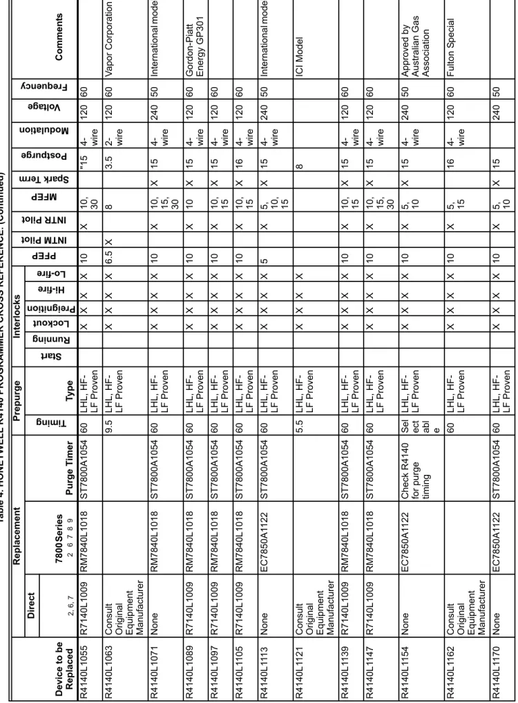
R4 140L 105 5 R 7140 L10 09 RM7 840L 101 8 ST78 00A10 54 60 LHL , HF -LF Prove n X X X X 10 X 10, 30 "15 4- wire 12 0 6 0 R4 140L 106 3 C onsul t Origi nal Equ ipm en t Ma nufacturer 9.5 LHL , HF-LF Prove n XX X X 6 .5 X 8 3. 5 2- wire 12 0 6 0 V apor Corp oration R4 140L 107 1 N one RM7 840L 101 8 ST78 00A10 54 60 LHL , HF -LF Prove n X X X X 10 X 10, 15, 30 X1 5 4- wire 24 0 5 0 In te rn ationa l mo del R4 140L 108 9 R 7140 L10 09 RM7 840L 101 8 ST78 00A10 54 60 LHL , HF -LF Prove n X X X X 1 0 X 10 X 15 4- wire 12 0 6 0 G o rd on-Pia tt Energy GP3 01 R4 140L 109 7 R 7140 L10 09 RM7 840L 101 8 ST78 00A10 54 60 LHL , HF -LF Prove n X X X X 10 X 10, 15 X1 5 4- wire 12 0 6 0 R4 140L 1105 R 7140 L10 09 RM7 840L 101 8 ST78 00A10 54 60 LHL , HF -LF Prove n X X X X 10 X 10, 15 X1 6 4- wire 12 0 6 0 R4 140L 11 13 N one EC7 850 A1 122 ST78 00A10 54 60 LHL , HF -LF Prove n XX X X 5 X 5, 10, 15 X1 5 4- wire 24 0 5 0 In te rn ationa l mo del R4 140L 1121 C onsul t Origi nal Equ ipm en t Ma nufacturer 5.5 LHL , HF-LF Prove n X X X X 8 ICI Model R4 140L 1139 R 7140 L10 09 RM7 840L 101 8 ST78 00A10 54 60 LHL , HF -LF Prove n X X X X 10 X 10, 15 X1 5 4- wire 12 0 6 0 R4 140L 1147 R 7140 L10 09 RM7 840L 101 8 ST78 00A10 54 60 LHL , HF -LF Prove n X X X X 10 X 10, 15, 30 X1 5 4- wire 12 0 6 0 R4 140L 1154 N one EC7 850 A1 122 Check R41 40 fo r pu rge timi ng Se l ect abl e LHL , HF -LF Prove n XX X X 1 0 X 5, 10 X1 5 4- wire 24 0 5 0 A pprove d b y
Australian Gas Ass
o ciation R4 140L 1162 C onsul t Origi nal Equ ipm en t Ma nufacturer 60 LHL , HF -LF Prove n XX X X 1 0 X 5, 15 16 4- wire 12 0 6 0 F u lto n S p ecial R4 140L 1170 N one EC7 850 A1 122 ST78 00A10 54 60 LHL , HF -LF Prove n XX X X 1 0 X 5, 10 X1 5 24 0 5 0 Ta b le 4. HONEYWEL L R41 40 PROGRA MMER
CROSS REFERENCE. (Continued)
Device to be Rep laced Rep lacem ent P rep u rg e In terloc ks PFEP INTM Pilo t INTR Pilo t MFEP Spar k T erm Postpurge Modulation Volt ag e Freq uenc y C o mme nt s Direct 78 00 Se ries 2 6 7 8 9 Purge T ime r Tim in g Ty p e Star t Runn ing Lo ckout Preignition Hi-fire Lo-fire 2, 6 , 7 Se e fo ot no te s on p ag e 16 .
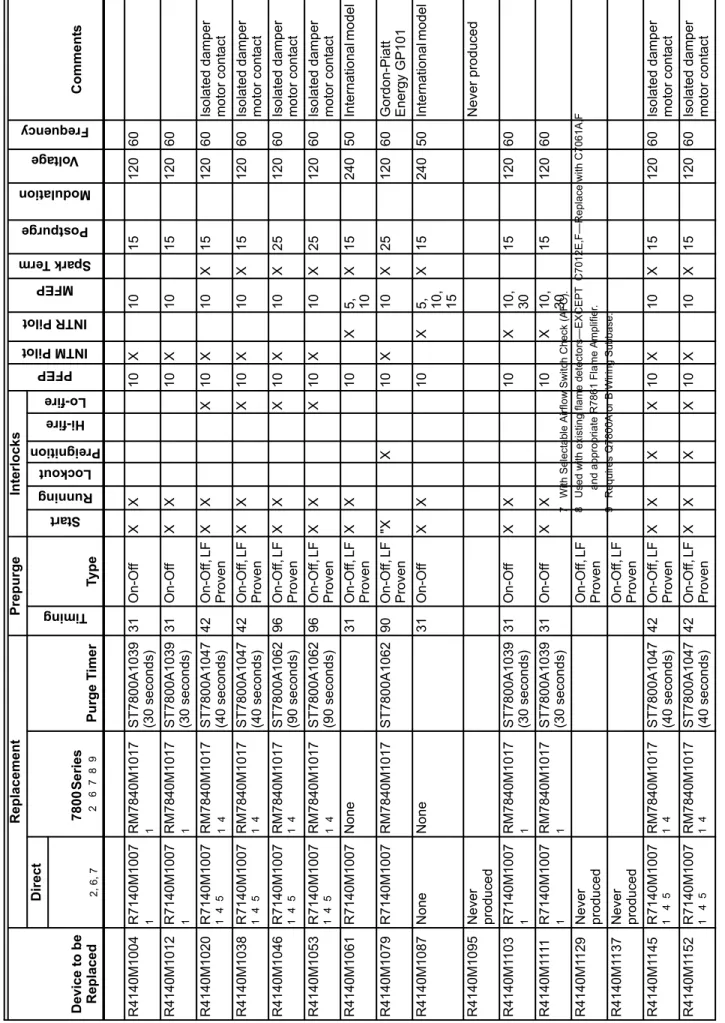
R4 140M10 04 R 7140 M1007 1 RM7 840M10 17 1 ST78 00A10 39 (30 second s) 31 O n -O ff X X 10 X 10 15 120 60 R4 140M10 12 R 7140 M1007 1 RM7 840M10 17 1 ST78 00A10 39 (30 second s) 31 O n -O ff X X 10 X 10 15 120 60 R4 140M10 20 R 7140 M1007 1 4 5 RM7 840M10 17 1 4 ST78 00A10 47 (40 second s) 42 On -Of f, LF Proven X X X 1 0 X 10 X 15 12 0 6 0 Iso lated da mp er m o to r co nt ac t R4 140M10 38 R 7140 M1007 1 4 5 RM7 840M10 17 1 4 ST78 00A10 47 (40 second s) 42 On -Of f, LF Proven X X X 1 0 X 10 X 15 12 0 6 0 Iso lated da mp er m o to r co nt ac t R4 140M10 46 R 7140 M1007 1 4 5 RM7 840M10 17 1 4 ST78 00A10 62 (90 second s) 96 On -Of f, LF Proven X X X 1 0 X 10 X 25 12 0 6 0 Iso lated da mp er m o to r co nt ac t R4 140M10 53 R 7140 M1007 1 4 5 RM7 840M10 17 1 4 ST78 00A10 62 (90 second s) 96 On -Of f, LF Proven X X X 1 0 X 10 X 25 12 0 6 0 Iso lated da mp er m o to r co nt ac t R4 140M10 61 R 7140 M1007 No ne 31 On -Of f, LF Proven XX 1 0 X 5, 10 X 15 24 0 5 0 In te rn ationa l mo del R4 140M10 79 R 7140 M1007 RM7 840M10 17 ST78 00A10 62 90 On -Of f, LF Proven "X X 1 0 X 10 X 25 12 0 6 0 Go rd on-Pia tt Energy GP1 01 R4 140M10 87 N one No ne 31 On -Of f X X 1 0 X 5, 10, 15 X 15 24 0 5 0 In te rn ationa l mo del R4 140M10 95 N ever p rodu ce d Never prod uced R4 140M1 1 03 R 7140 M1007 1 RM7 840M10 17 1 ST78 00A10 39 (30 second s) 31 O n -O ff X X 10 X 10, 30 15 12 0 6 0 R4 140M1 11 1 R 7140 M1007 1 RM7 840M10 17 1 ST78 00A10 39 (30 second s) 31 O n -O ff X X 10 X 10, 30 15 12 0 6 0 R4 140M1 1 29 N ever p rodu ce d On -Of f, LF Proven R4 140M1 1 37 N ever p rodu ce d On -Of f, LF Proven R4 140M1 1 45 R 7140 M1007 1 4 5 RM7 840M10 17 1 4 ST78 00A10 47 (40 second s) 42 On -Of f, LF Proven X X X X 1 0 X 10 X 15 12 0 6 0 Iso lated da mp er m o to r co nt ac t R4 140M1 1 52 R 7140 M1007 1 4 5 RM7 840M10 17 1 4 ST78 00A10 47 (40 second s) 42 On -Of f, LF Proven X X X X 1 0 X 10 X 15 12 0 6 0 Iso lated da mp er m o to r co nt ac t Ta b le 4. HONEYWEL L R41 40 PROGRA MMER
CROSS REFERENCE. (Continued)
Device to be Rep laced Rep lacem ent P rep u rg e In terloc ks PFEP INTM Pilo t INTR Pilo t MFEP Spar k T erm Postpurge Modulation Volt ag e Freq uenc y C o mme nt s Direct 78 00 Se ries 2 6 7 8 9 Purge T ime r Tim in g Ty p e Star t Runn ing Lo ckout Preignition Hi-fire Lo-fire 2, 6 , 7 7 With S e lect ab le Airflow Switch Ch eck (AFC). 8 U sed wit h existin g fla m e de te ct or s—EXCE P T C70 12E, F —Rep lace with C70 61A, F and app ropr iat e R7 861 Flame Ampl ifie r. 9 R equir e s Q 7800A o r B Wi ring Su bbase. See fo ot no te s on p ag e 16 .
R4 140M1 1 60 R 7140 M1007 4 5 RM7 840M10 17 4 ST78 00A10 62 (90 second s) 96 On -Of f, LF Proven X X X 1 0 X 10 X 25 12 0 6 0 Iso lated da mp er m o to r co nt ac t R4 140M1 1 78 R 7140 M1007 4 5 RM7 840M10 17 4 ST78 00A10 62 (90 second s) 96 On -Of f, LF Proven X X X 1 0 X 10 X 25 12 0 6 0 Iso lated da mp er m o to r co nt ac t R4 140M1 1 86 R 7140 M1007 1 5 RM7 840M10 17 1 ST78 00A10 47 (40 second s) 42 On -Of f, LF Proven XX X 1 0 X 10 X 15 12 0 6 0 R4 140M1 1 94 R 7140 M1007 1 5 RM7 840M10 17 1 ST78 00A10 62 (90 second s) 96 On -Of f, LF Proven XX X 1 0 X 10 X 15 12 0 6 0 R4 140M12 02 N one No ne 31 On -Of f, LF Proven XX X 5 X 5, 10 X 15 240 50 Ap pr ov ed by
Australian Gas Ass
o ciation R4 140M12 10 C onsul t Ori gina l Equip m e nt Ma nufacturer 31 On -Of f, LF Proven X X 10 X 10 25 120 60 F u lton S p ec ia l R4 140P1 007 N one RM7 896C 1010 ST78 00A10 62 90 On -Of f X X 1 0 X 15 15 12 0 6 0 Go rd on Piatt GP00 1 R4 140Y1 005 N one RM7 895A1 014 ST78 00A10 13 7 O n -Of f X X 1 0 X 15 15 12 0 6 0 R4 140Y1 013 N one RM7 895A1 014 ST78 00A10 13 7 O n -Of f X X 4 X 15 15 12 0 6 0 R4 140Y1 021 N one RM7 895A1 014 ST78 00A10 39 30 On -Of f X X 1 0 X 15 15 12 0 6 0 R4 140Y1 039 N one RM7 895A1 014 ST78 00A10 39 30 On -Of f X X 4 X 15 15 12 0 6 0 R4 140Y1 047 N one RM7 895A1 014 ST78 00A10 54 60 On -Of f X X 1 0 X 15 15 12 0 6 0 R4 140Y1 054 N one RM7 895A1 014 ST78 00A10 54 60 On -Of f X X 4 X 15 15 12 0 6 0 R4 140Y1 062 N one RM7 895A1 014 ST78 00A10 62 90 On -Of f X X 1 0 X 15 15 12 0 6 0 R4 140Y1 070 N one RM7 895A1 014 ST78 00A10 62 90 On -Of f X X 4 X 15 15 12 0 6 0 Ta b le 4. HONEYWEL L R41 40 PROGRA MMER
CROSS REFERENCE. (Continued)
Device to be Rep laced Rep lacem ent P rep u rg e In terloc ks PFEP INTM Pilo t INTR Pilo t MFEP Spar k T erm Postpurge Modulation Volt ag e Freq uenc y C o mme nt s Direct 78 00 Se ries 2 6 7 8 9 Purge T ime r Tim in g Ty p e Star t Runn ing Lo ckout Preignition Hi-fire Lo-fire 2, 6 , 7 See fo ot no te s on p ag e 16 .
FOOTNOTES: 1 R41 40 S tart Inter lock s become Pr e-Ignition Interlocks ( m ust remai n clo se d thro ugho ut Pu rge) . 2 4 or 10 secon d P F EP . 3 60 second MFEP is not availa ble with re placeme n t device. 4 S p ring ret u rn Firi ng Rate Mo tor (d amper mot o r) . 5 Remov e Jumpers J1 and J2. 6 S e lect pr oper amp lif ier: Old A m plifier Ne w A m p lif ier R72 47A1 005 R7 847A 1033 R72 47A1 021 R7 847A 1025 R72 47B1 003 R7 847B 1031 R72 47C10 01 R786 1A10 26 Se e No te 8 R7 24 8 C 1 00 4 R7 8 48 A 1 00 8 R72 48B1 028 R7 848B 1006 R72 49A1 003 R7 849A 1023 R74 76A1 007 R7 886A 1001 7 With Se lect abl e A irflow Switc h Che ck (AFC). 8 Used wit h exist ing f lame de tect ors—EXCEP T C70 12E, F —Re p lace with C 7061 A,F and ap prop riat e 7861 Flame A m plif ier . 9 Req u ire s Q7 800A or Q 7800 B W iring Su bbase.
Ta ble 5. HON E YWELL R 41
50 PROGRAMMER CROSS REFERENCE.
Device to b e Rep laced Re pl ac em en t P re purg e In terlo cks PFEP INTM Pilo t INTR Pilo t MFEP Spar k T erm Postpurge Modulation Volt ag e Freq uenc y Co m m en ts Dir ect 1, 2, 6, 7, 8 78 00 S er ie s 1, 2 , 6, 7 , 8, 9 Purge T ime r Tim in g Typ e Star t Runn ing Lo ckout Preignition Hi-fire Lo-fire R4 150A1 007 N one RM784 0M101 7 ST 780 0A103 9 30 O n-Of f X X 10 X 15 1 5 12 0 6 0 Inclu des R725 7 Amp lif ie r. R4 150A1 015 N one RM784 0M101 7 ST 780 0A103 9 30 O n-Of f X X 10 X 15 1 5 12 0 5 0 R4 150A1 023 N one RM784 0M101 7 ST 780 0A103 9 30 O n-Of f X X 10 X 15 1 5 12 0 6 0 R4 150A1 031 N one RM784 0M101 7 ST 780 0A103 9 30 O n-Of f X X 10 X 15 , 30 X 1 5 12 0 6 0 Kew anee label . R4 150A1 049 Intern ati ona l Mo del 30 On-Of f X X 10 X 5 X 1 5 20 0 6 0 Inclu des R725 7 Internat ional model. R4 150A1 056 N one RM784 0M101 7 ST 780 0A103 9 30 O n-Of f X X 15 X 15 X 1 5 12 0 6 0 R4 150A1 064 N one RM784 0M101 7 ST 780 0A103 9 30 O n-Of f X X 10 X 15 , 30 15 12 0 6 0 R4 150A1 072 Intern ati ona l Mo del 30 On-Of f X X 10 X 15 1 5 20 0 6 0 Interna tio nal mod el. R4 150A1 080 N one RM784 0M101 7 ST 780 0A103 9 30 O n-Of f X X 10 X 15 , 30 X 1 5 12 0 6 0 Kew anee label . R4 150A1 098 N ever Pro duced Ne ver p roduce d R4 150A1 106 N one RM784 0M101 7 ST 780 0A103 9 30 O n-Of f X X 15 X 5 X 1 5 12 0 6 0 R4 150A1 114 N one RM784 0M101 7 ST 780 0A105 4 60 O n-Of f X X 10 X 15 12 0 6 0 R4 150A1 122 N one RM784 0M101 7 ST 780 0A106 2 90 O n-Of f X X 10 X 15 1 5 12 0 6 0 R4 150A1 130 N one RM784 0M101 7 ST 780 0A105 4 60 O n-Of f X X 10 X 15 , 30 20 12 0 6 0 R4 150A1 148 N one RM784 0M101 7 ST 780 0A106 2 90 O n-Of f X X 10 X 15 , 30 15 12 0 6 0 R4 150A1 155 N one RM784 0M101 7 ST 780 0A106 2 90 O n-Of f X X 10 X 15 , 30 X 1 5 12 0 6 0 Kew anee label . R4 150A1 163 N one RM784 0M101 7 ST 780 0A103 9 30 O n-Of f X X 15 X 15 X 1 5 12 0 6 0 R4 150A1 171 N one RM784 0M101 7 ST 780 0A106 2 90 O n-Of f X X 15 X X 1 5 12 0 6 0 R4 150A1 189 N one RM784 0M101 7 ST 780 0A106 2 90 O n-Of f X X 15 X 15 X 2 0 12 0 6 0 R4 150A1 197 N one RM784 0M101 7 ST 780 0A103 9 30 O n-Of f X X 10 X 15 1 5 12 0 5 0 Interna tio nal mod el R4 150A1 205 Intern ati ona l Mo del 37 On-Of f X X 10 X 2 2 0 22 0 5 0 Interna tio nal mod el R4 150A1 213 Intern ati ona l Mo del 37 On-Of f X X 10 X 5 2 0 22 0 5 0 Interna tio nal mod el R4 150A1 221 Intern ati ona l Mo del 37 On-Of f X X 10 X 5 2 0 24 0 5 0 Interna tio nal mod el R4 150A1 239 N one RM784 0M101 7 ST 780 0A106 2 90 O n-Of f X X 15 X 15 X 2 0 12 0 6 0 See footnotes on p a ge 22.
R4 150A1 247 N one RM784 0M101 7 ST 780 0A103 9 30 O n-Of f X X 10 X 15 1 5 12 0 6 0 R4 150A1 254 N one RM784 0M101 7 ST 780 0A106 2 90 O n-Of f X X 10 X 15 2 0 12 0 6 0 R4 150A1 262 Intern ati ona l Mo del 30 On-Of f X X 10 X 15 X 1 5 22 0 5 0 Interna tio nal mod el R4 150A1 270 N one RM784 0M101 7 ST 780 0A103 9 30 O n-Of f X X 30 X 15 1 5 12 0 6 0 R4 150A1 288 N one RM784 0M101 7 ST 780 0A104 7 (40 seconds) 35 On-Of f X X 10 X 15 1 5 12 0 6 0 5 secon d st abil ization b efo re PFEP . R4 150A1 296 Intern ati ona l Mo del 30 On-Of f X X 10 X 15 1 5 22 0 5 0 Interna tio nal mod el. Igni tion on 3 secs be fo re pilo t valve . R4 150B1 005 N one RM784 0M101 7 ST 780 0A103 9 30 O n-Of f X X 10 X 15 1 5 12 0 6 0 R 7 258A in cl ude d R4 150B1 013 N ever Pro duced Ne ver p roduce d R4 150C 1003 N one RM784 0M101 7 ST 780 0A103 9 30 O n-Of f X X 10 X 15 1 5 12 0 6 0 R 7 259A in cl ude d R4 150C 101 1 N ever Pro duced R4 150C 1029 N one RM784 0M101 7 ST 780 0A103 9 30 O n-Of f X X 10 X 10 1 5 12 0 6 0 R 7 259A in cl ude d R4 150D 1001 N ever Pro duced Ne ver p roduce d R4 150E1 008 N one Non e 30 X X 3 15 12 0 6 0 F or direct sp ark ig nition a ppl ications R4 150F 10 06 Intern ati ona l Mo del Internat ional - Jap an R4 150F 10 14 Intern ati ona l Mo del Internat ional - Jap an R4 150G10 04 R 7140 G2 008 RM784 0G1 014 ST 780 0A105 4 (60 seconds) 50 LHL, LF Proven XX X 9 X 15 8 3- wire 12 0 6 0 R4 150G10 12 R 7140 M1007 4, 5 RM784 0M101 7 ST 780 0A106 2 (90 seconds) 72 On-Of f, LF Proven XX X 13 X 15 X 1 5 12 0 6 0 Ta b le 5. HON E YW ELL R 41 50 PROGRA
MMER CROSS REFERENCE. (Continued)
Device to b e Rep laced Re pl ac em en t P re purg e In terlo cks PFEP INTM Pilo t INTR Pilo t MFEP Spar k T erm Postpurge Modulation Volt ag e Freq uenc y Co m m en ts Dir ect 1, 2, 6, 7, 8 78 00 S er ie s 1, 2 , 6, 7 , 8, 9 Purge T ime r Tim in g Typ e Star t Runn ing Lo ckout Preignition Hi-fire Lo-fire See fo ot no te s on p ag e 22 .
R4 150G10 20 R 7140 G2 008 RM784 0G1 014 ST 780 0A105 4 (60 seconds) 50 LHL, LF Proven XX X 9 X 10 8 3- wire 12 0 6 0 K ew anee label R4 150G10 38 Intern ati ona l Mo del 50 LHL, LF Proven XX X 9 X 15 8 3- wire 22 0 5 0 Interna tio nal mod el R4 150G10 46 R 7140 G2 008 RM784 0G1 014 ST 780 0A105 4 (60 seconds) 50 LHL, LF Proven XX X 9 X 10 8 3- wire 12 0 6 0 R4 150G10 53 C onsul t Ori gina l Equip m e nt Man ufactu rer 72 LHL, LF Proven XX X 10 X 10 , 15 93 - wire 12 0 6 0 C leaver Brooks CB2 R4 150G10 61 C onsul t Ori gina l Equip m e nt Man ufactu rer 72 LHL, LF Proven XXX X 10 X 10 , 15 15 3- wire 12 0 6 0 C leaver Brooks CB4, CB4 -1 R4 150G10 79 R 7140 M1007 RM784 0M101 7 ST 780 0A106 2 (90 seconds) 72 LHL, LF Proven XX X 13 X 15 X 1 5 12 0 6 0 R4 150G10 87 C onsul t Ori gina l Equip m e nt Man ufactu rer 72 LHL, LF Proven XX X 10 X 10 , 15 15 4- wire 12 0 6 0 C leaver Brooks CB2 -1 R4 150G10 95 N ever Pro duced Ne ver p roduce d R4 150G1 10 3 R 7140 G2 008 RM784 0G1 014 ST 780 0A105 4 60 LHL, LF Proven XX X 10 X 10 , 30 15 3- wire 12 0 6 0 R4 150G1 11 1 R 7140 G2 008 RM784 0G1 014 ST 780 0A105 4 60 LHL, LF Proven X X X 10 X 15 1 5 4- wire 12 0 6 0 R4 150G1 12 9 N one RM784 0L10 18 ST 780 0A105 4 60 LHL, LF Proven XX X X 10 X 10 1 5 4- wire 12 0 6 0 G ordon -Piatt Energy GP200 R4 150G1 13 7 R 7140 G2 008 RM784 0G1 014 ST 780 0A105 4 60 LHL, LF Proven XX X 10 X 10 , 30 15 4- wire 12 0 6 0 R4 150G1 14 5 R 7140 G2 008 RM784 0G1 014 ST 780 0A105 4 60 LHL, LF Proven X X X 10 X 10 1 5 4- wire 12 0 6 0 Ta b le 5. HON E YW ELL R 41 50 PROGRA
MMER CROSS REFERENCE. (Continued)
Device to b e Rep laced Re pl ac em en t P re purg e In terlo cks PFEP INTM Pilo t INTR Pilo t MFEP Spar k T erm Postpurge Modulation Volt ag e Freq uenc y Co m m en ts Dir ect 1, 2, 6, 7, 8 78 00 S er ie s 1, 2 , 6, 7 , 8, 9 Purge T ime r Tim in g Typ e Star t Runn ing Lo ckout Preignition Hi-fire Lo-fire Se e fo ot no te s on p ag e 22 .
R4 150G1 15 2 N ever Pro duced Ne ver p roduce d R4 150G1 16 0 C onsul t Ori gina l Equip m e nt Man ufactu rer 72 LHL, LF Proven XX X 10 X 10 , 15 15 4- wire 12 0 6 0 C leaver Brooks C B 2 -1A R4 150G1 17 8 R 7140 G2 008 RM784 0G1 014 ST 780 0A105 4 60 LHL, LF Proven X X X 10 X 15 1 5 4- wire 12 0 6 0 R4 150G1 18 6 R 7140 G1 000 RM784 0G1 014 ST 780 0A105 4 60 LHL, LF Proven XX X 10 X 10 , 15 15 4- wire 12 0 6 0 R4 150G1 19 4 N ever Pro duced Ne ver p roduce d R4 150G12 02 Intern ati ona l Mo del 62 LHL, LF Proven "X X X X 10 X 5 X 1 5 4- wire 24 0 5 0 Interna tio nal mod el to G o rd on-Piat t Energy Speci fic a tions. R4 150H 1002 Intern ati ona l Mo del 30 On-Of f X X 9 X 13 , 58 15 3- wire 12 0 6 0 Interna tio nal mod el R4 150H 1010 Intern ati ona l Mo del 30 On-Of f X X 9 X 13 , 58 15 3- wire 24 0 6 0 Interna tio nal mod el R4 150H 1028 Intern ati ona l Mo del 30 On-Of f X X 9 X 13 , 58 15 3- wire 22 0 5 0 Interna tio nal mod el R4 150H 1036 Intern ati ona l Mo del 30 On-Of f X X 9 X 13 , 58 15 3- wire 20 8 6 0 R4 150J1 007 Intern ati ona l Mo del 37 On-Of f X 5 X 2 2 0 22 0 5 0 Interna tio nal mod el R4 150K1 005 Intern ati ona l Mo del 37 On-Of f X 5 X 5 2 0 22 0 5 0 Interna tio nal mod el R4 150L 100 3 R 7140 L10 09 RM784 0L10 18 ST 780 0A106 2 (90 seconds) 72 LHL, HF-L F Pr oven XXX X 10 X 10 , 15 15 3- wire 12 0 6 0 R4 150L 101 1 R 7140 L10 09 RM784 0L10 18 ST 780 0A106 2 (90 seconds) 72 LHL, HF-L F Pr oven XXX X 10 X 10 , 15 15 3- wire 12 0 6 0 Ta b le 5. HON E YW ELL R 41 50 PROGRA
MMER CROSS REFERENCE. (Continued)
Device to b e Rep laced Re pl ac em en t P re purg e In terlo cks PFEP INTM Pilo t INTR Pilo t MFEP Spar k T erm Postpurge Modulation Volt ag e Freq uenc y Co m m en ts Dir ect 1, 2, 6, 7, 8 78 00 S er ie s 1, 2 , 6, 7 , 8, 9 Purge T ime r Tim in g Typ e Star t Runn ing Lo ckout Preignition Hi-fire Lo-fire See footnotes on p a ge 22.
R4 150L 102 9 R 7140 L10 09 RM784 0L10 18 ST 780 0A105 4 60 LHL, HF-L F Pr oven X X X X 10 X 10 1 5 4- wire 12 0 6 0 G ordon -Piatt Energy GP300 (orig ina l) R4 150L 103 7 R 7140 L10 09 RM784 0L10 18 ST 780 0A106 2 (90 seconds) 72 LHL, HF-L F Pr oven XXX X 10 X 10 , 15 15 4- wire 12 0 6 0 R4 150L 104 5 R 7140 L10 09 RM784 0L10 18 ST 780 0A106 2 (90 seconds) 72 LHL, HF-L F Pr oven XXX X 10 X 10 , 15 15 4- wire 12 0 6 0 R4 150L 105 2 N ever Pro duced Ne ver p roduce d R4 150L 106 0 C onsul t Ori gina l Equip m e nt Man ufactu rer 72 LHL, HF-L F Pr oven XXX X 10 X 10 , 15 15 4- wire 12 0 6 0 C leaver Brooks C B 4 -1A R4 150L 107 8 R 7140 L10 09 RM784 0L10 18 ST 780 0A105 4 60 LHL, HF-L F Pr oven X X X X 10 X 10 1 5 4- wire 12 0 6 0 G ordon -Piatt Energy GP300 R4 150M10 01 R 7140 M1007 RM784 0M101 7 ST 780 0A106 2 90 O n-Of f X X 10 X 10 2 0 12 0 6 0 R a y Burn er R4 150M10 19 N one RM784 0M101 7 ST 780 0A106 2 90 O n-Of f X X 10 X 10 2 0 12 0 6 0 R a y Burn er - S pecia l Base R4 150M10 27 R 7140 M1007 RM784 0M101 7 ST 780 0A103 9 30 O n-Of f X X 10 X 15 1 5 12 0 6 0 R4 150M10 35 R 7140 M1007 RM784 0M101 7 ST 780 0A103 9 30 O n-Of f X X 10 X 15 1 5 12 0 6 0 R4 150M10 43 R 7140 M1007 RM784 0M101 7 ST 780 0A103 9 30 O n-Of f X X 10 X 15 X 1 5 12 0 6 0 R4 150M10 50 R 7140 M1007 RM784 0M101 7 ST 780 0A103 9 30 O n-Of f X X 10 X 15 , 30 15 12 0 6 0 R4 150M10 68 R 7140 M1007 RM784 0M101 7 ST 780 0A106 2 90 O n-Of f X X 10 X 15 1 5 12 0 6 0 R4 150M10 76 R 7140 M1007 RM784 0M101 7 ST 780 0A106 2 90 O n-Of f X X 10 X 15 X 1 5 12 0 6 0 R4 150M10 84 R 7140 M1007 RM784 0M101 7 ST 780 0A106 2 90 O n-Of f X X 10 X 15 1 5 12 0 6 0 R4 150M10 92 N one RM784 0M101 7 ST 780 0A106 2 90 O n-Of f X X 10 X 15 X 2 0 12 0 6 0 Gordon -Piatt Energy GP100 (orig ina l) R4 150M1 1 00 R 7140 M1007 RM784 0M101 7 ST 780 0A103 9 30 O n-Of f X X 10 X 10 , 30 15 12 0 6 0 R4 150M1 118 N one RM784 0M101 7 ST 780 0A103 9 30 O n-Of f X X 15 X 15 X 1 5 12 0 6 0 R4 150M1 1 26 R 7140 M1007 RM784 0M101 7 ST 780 0A103 9 30 O n-Of f X X 10 X 10 X 1 5 12 0 6 0 Ta b le 5. HON E YW ELL R 41 50 PROGRA
MMER CROSS REFERENCE. (Continued)
Device to b e Rep laced Re pl ac em en t P re purg e In terlo cks PFEP INTM Pilo t INTR Pilo t MFEP Spar k T erm Postpurge Modulation Volt ag e Freq uenc y Co m m en ts Dir ect 1, 2, 6, 7, 8 78 00 S er ie s 1, 2 , 6, 7 , 8, 9 Purge T ime r Tim in g Typ e Star t Runn ing Lo ckout Preignition Hi-fire Lo-fire Se e fo ot no te s on p ag e 22 .
FO OT NO TES: 1 R41 50 S tart Inter lock s become Pr e-Ignition Interlocks ( m ust remai n clo se d thro ugho ut Pu rge) . 2 4 or 10 secon d P F EP . 3 60 S e
cond MFEP is not
a va ilable wit h repl acement device. 4 S p ring ret u rn Firi ng Rate Mo tor (d amper mot o r) . 5 Remov e Jumpers J1 and J2. 6 S e lect pr oper amp lif ier: O ld A m p lif ier Re p la ce m en t A m plifie r R 7257A 1028 R7 847A 1033 R 7258A 1001 R7 848A 1008 R 7259A 1000 R7 849A 1023 7 Wit h Se lect abl e A ir F low S witch Check (A FC). 8 Use with e xist ing f lame det ect o rs—E XCEP T C701 2E, F —re p lace with C70 61A ,F and app ropr iat e R7 861 Flame Ampl ifie r. 9 Req u ire s Q7 800A or Q 7800 B W iring Su bbase. R4 150M1 1 34 R 7140 M1007 RM784 0M101 7 ST 780 0A103 9 30 O n-Of f X X 10 X 10 1 5 12 0 6 0 R4 150M1 1 42 R 7140 M1007 RM784 0M101 7 ST 780 0A106 2 90 O n-Of f X X 10 X 10 X 2 0 12 0 6 0 R4 150M1 1 59 R 7140 M1007 RM784 0M101 7 ST 780 0A106 2 90 O n-Of f X X 10 X 10 2 0 12 0 6 0 R4 150M1 1 67 N ever Pro duced Ne ver p roduce d R4 150M1 1 75 N one RM784 0M101 7 ST 780 0A106 2 90 O n-Of f X X 10 X 10 X 2 0 12 0 6 0 Gordon -Piatt Energy GP100 R4 150X1 004 Intern ati ona l Mo del 30 On-Of f X X 5 X 5 X 1 5 22 0 5 0 Interna tio nal mod el R4 150X1 012 Intern ati ona l Mo del 30 On-Of f X X 5 X 5 X 1 5 24 0 5 0 Interna tio nal mod el R4 150X1 020 Intern ati ona l Mo del Internat ional model Ta b le 5. HON E YW ELL R 41 50 PROGRA
MMER CROSS REFERENCE. (Continued)
Device to b e Rep laced Re pl ac em en t P re purg e In terlo cks PFEP INTM Pilo t INTR Pilo t MFEP Spar k T erm Postpurge Modulation Volt ag e Freq uenc y Co m m en ts Dir ect 1, 2, 6, 7, 8 78 00 S er ie s 1, 2 , 6, 7 , 8, 9 Purge T ime r Tim in g Typ e Star t Runn ing Lo ckout Preignition Hi-fire Lo-fire
Ta ble 6. HONEYWELL 7800 SERIES PROGRA MMER, PR IMAR Y CONTROL CROSS REFER E N C E. D evice to b e Rep lac ed Curre nt Rep lac emen t Prep urg e In te rl oc ks PFEP INTM Pil ot IN TR Pilo t MFEP Postpurge Volt ag e Freq uenc y Modulation Comm ent s Ti m in g Ty p e Star t Running Lo ckout Prei gnit io n Hi-fire Lo-fire Air-Flow SW Che ck Run/Tes t Switch Flmae T imer RM78 00E10 02 RM780 0E101 0 Se lect able LHL H F, LF PR V X X X X X X 4 , 10 X1 0 , 15 1 5 12 0 50 4-w ire
with Energy Savin
g Pu rge and disp lay mo dule RM78 00E10 10 RM780 0E101 0 Se lect able LHL H F, LF PR V X X X X X X 4 , 10 X1 0 , 15 1 5 12 0 50/ 60 4-w ire
with Energy Savin
g Pu rge and disp lay mo dule RM78 00G100 0 RM780 0G1 018 Se lect able LHL L F PR V X X X X X 4 , 10 XX 10 , 15 , 30 1 5 12 0 50 4-w ire W ith di sp lay modul e RM78 00G101 8 RM780 0G1 018 Se lect able LHL L F PR V X X X X X 4 , 10 XX 10 , 15 , 30 1 5 12 0 50/ 60 4-w ire With di sp lay modul e RM78 00L1 004 RM780 0L10 12 Se lect able LHL H F, LF PR V X X X X X X 4 , 10 X1 0 , 15 1 5 12 0 50 4-w ire W ith di sp lay modul e RM78 00L1 012 RM780 0L10 12 Se lect able LHL H F, LF PR V X X X X X X 4 , 10 X1 0 , 15 1 5 12 0 50/ 60 4-w ire With di sp lay modul e RM78 00L1 038 RM780 0L10 38 Se lect able LHL H F, LF PR V X X X X X X 4 , 10 X1 0 , 15 1 5 12 0 50/ 60 4-w ire Fu lto n Proprie ta ry RM78 00L1 046 RM780 0L10 46 Se lect able LHL H F, LF PR V X X X X X X 4 , 10 X1 0 , 15 1 5 12 0 50/ 60 4-w ire V apor Propri et a ry (49 3200 86) RM78 00L1 053 RM780 0L10 53 Se lect able LHL H F, LF PR V X X X X X X 4 , 10 XX 10 , 15 1 5 12 0 50/ 60 4-w ire With di sp lay modul e-Inte rmi tten t Pilot RM78 00L1 061 RM780 0L10 79 Se lect able LHL H F, LF PR V X X X X X X 4 , 10 X1 0 , 15 1 5 12 0 50/ 60 4-w ire Clea ver Bro ok Prop riet ary (8 33-271 9) RM78 00L1 079 RM780 0L10 79 Se lect able LHL H F, LF PR V X X X X X X 4 , 10 X1 0 , 15 1 5 12 0 50/ 60 4-w ire Clea ver Bro ok Prop riet ary (8 33-271 8) RM78 00M10 03 RM780 0M101 1 Se lect able LHL L F PR V X X X X X 4, 10 X X 10 1 5 12 0 50 2-w ire W ith di sp lay modul e RM78 00M10 11 RM780 0M101 1 Se lect able LHL L F PR V X X X X X 4, 10 X X 10 1 5 12 0 50/ 60 2-w ire With di sp lay modul e RM78 00M10 36 RM780 0M1036 Se lect able LHL L F PR V X X X X X 4, 10 X X 10 1 5 12 0 50/ 60 2-w ire Fu lto n Proprie ta ry
RM78 38A10 06 RM783 8A101 4 Se lect able LHL HF PR V X X 4 , 10 X 12 0 50
Semi-automatic control, with disp
lay mo dule RM78 38A10 14 RM783 8A101 4 Se lect able LHL HF PR V X X 4 , 10 X 12 0 50/ 60 Semi-automatic control, with disp
lay mo dule RM78 38B10 05 RM783 8B101 3 Se lect able LHL H F, LF PR V X X X X X X X 4, 10 X 10 12 0 50 With di sp lay modul e RM78 38B10 13 RM783 8B101 3 Se lect able LHL H F, LF PR V X X X X X X X 4, 10 X X 10 12 0 50/ 60 With di sp lay modul e RM78 38C1 004 RM783 8C10 04 Se lect able LHL H F, LF PR V X X X X X X X 4, 10 X X 15 12 0 50/ 60 With di sp lay modul e, Ala rm soun ds o nly on safety shu td own, Req uires ST78 00C type Purge Ti m er RM78 40E10 08 RM784 0E101 6 Se lect able LHL H F, LF PR V X X X X X X 4 , 10 X1 0 , 15 1 5 12 0 50 4-w ire
with Energy Savin
g Pu rge RM78 40E10 16 RM784 0E101 6 Se lect able LHL H F, LF PR V X X X X X X 4 , 10 X1 0 , 15 1 5 12 0 50/ 60 4-w ire
with Energy Savin
g Pu rge RM78 40G100 6 RM784 0G1 014 Se lect able LHL L F PR V X X X X X 4 , 10 XX 10 , 15 , 30 15 12 0 50 4-wi re RM78 40G101 4 RM784 0G1 014 Se lect able LHL L F PR V X X X X X 4 , 10 XX 10 , 15 , 30 1 5 12 0 50/ 60 4-w ire RM78 40L1 000 RM784 0L10 18 Se lect able LHL H F, LF PR V X X X X X X 4 , 10 X1 0 , 15 15 12 0 50 4-wi re RM78 40L1 018 RM784 0L10 18 Se lect able LHL H F, LF PR V X X X X X X 4 , 10 X1 0 , 15 1 5 12 0 50/ 60 4-w ire RM78 40L1 026 RM784 0L10 26 Se lect able LHL H F, LF PR V X X X X X X 4 , 10 XX 10 , 15 1 5 12 0 50/ 60 4-w ire In te rmi ttent Pilot Ta ble 6. HONEYWELL 7800 SERIES PROGRAM M ER, PR IMAR Y
CONTROL CROSS REFE
RE NC E. (C o n tin u ed ) D evice to b e Rep lac ed Curre nt Rep lac emen t Prep urg e In te rl oc ks PFEP INTM Pilo t INTR Pilo t MFEP Postpurge Volt ag e Freq uenc y Modulation Comm ent s Ti m in g Ty p e Star t Runn ing Lo ckout Preignition Hi-fire
Lo-fire Flow SW Ch eck Run/T est Swit ch Flm ae Time r
RM78 40L1 034 RM784 0L10 42 Se lect able LHL H F, LF PR V X X X X X X 4 , 10 X1 0 , 15 1 5 12 0 50/ 60 4-w ire Clea ver Bro ok Prop riet ary (8 33-272 1) RM78 40L1 042 RM784 0L10 42 Se lect able LHL H F, LF PR V X X X X X X 4 , 10 X1 0 , 15 1 5 12 0 50/ 60 4-w ire Clea ver Bro ok Prop riet ary (8 33-272 0) RM78 40M10 09 RM784 0M1017 Se lect able LHL L F PR V X X X X X 4, 10 X X 10 1 5 12 0 50 2-w ire RM78 40M10 17 RM784 0M1017 Se lect able LHL L F PR V X X X X X 4, 10 X X 10 1 5 12 0 50/ 60 2-w ire Ta ble 6. HONEYWELL 7800 SERIES PROGRAM M ER, PR IMAR Y
CONTROL CROSS REFE
RE NC E. (C o n tin u ed ) D evice to b e Rep lac ed Curre nt Rep lac emen t Prep urg e In te rl oc ks PFEP INTM Pilo t INTR Pilo t MFE P Postpurge Volt ag e Freq uenc y Modulation Comm ent s Ti m in g Ty p e Star t Runn ing Lo ckout Preignition Hi-fire
Lo-fire low SW -F Air Check Run/T est Swit ch Flm ae Time r
Ta ble 7. FIREYE™ T O HONEYWEL L PROGRAM M ER CROSS REFERENCE. D evice to b e Rep la ced Current Replac emen t 4 1 2 7800 Se rie s R ep la ce m e n t 1 2 3 6 12 13 20 23 32 33 Prep ur ge In terlo cks PFEP INTM Pil ot IN TR Pilo t MFEP Sp ark T erm Postpurge Modulation Volt ag e Freq uenc y C o mme nt s Tim in g Ty p e Star t Running Locko ut Preignition Hi-fire Lo-fire Lo-Fire On-Off LHL LHL PR V OP Damp 24 CJ5 100 0 Non e RM78 40M101 7 or RM7840 L10 18 33 X X X 7 X 10 8 12 0 50 / 60 4 sec FFR T, rectification type flam e sensor , vacuum tu be circuitry . 24 CJ5 300 0 Non e RM78 40M101 7 or RM7840 L10 18 3 0 X X X 7 X X 10 X 15 1 20 60 2-4 sec FF R T, rectificatio n typ e fla m e se nsor ." 24 CJ5 301 0 Non e RM78 40M101 7 or RM7840 L10 18 3 7 X X X X 7 X 10 X 15 1 20 60 2-4 sec FF R T, rectificatio n typ e fla m e se nsor . 24 CJ5 301 1 Non e RM78 40M101 7 or RM7840 L10 18 9 8 X X X X 7 X 10 X 25 1 20 60 1-4 sec FF R T, rectificatio n typ e fla m e se nsor . 24 CJ5 301 4 Non e RM78 40G101 4 or RM7840 L10 18 6 0 X X X X 7 X 10 20 3- wire 120 60 1-4 sec FFR T, rectification typ e fla m e se nsor . 24 CJ5 501 0 Non e RM78 40M101 7 or RM7840 L10 18 3 7 X X X X 5 X 10 X 15 1 20 60 1-4 sec FF R T, rectificatio n typ e fla m e se nsor . 24 CJ5 501 1 Non e RM78 40M101 7 or RM7840 L10 18 9 8 X X X X 5 X 10 X 25 1 20 60 1-4 sec FF R T, rectificatio n typ e fla m e se nsor . 24 CJ5 501 5 Non e RM78 40G101 4 or RM7840 L10 18 6 0 X XXX 7 X 10 , 15 15 4- wire 1 20 50/ 60 4 sec FFR T, rectification typ e fla m e se nsor . 24 CJ5 501 5A Non e RM78 40G101 4 or RM7840 L10 18 6 0 X XXX 7 X 10 , 15 15 4- wire 1 20 50/ 60 4 sec FFR T, rectification typ e fla m e se nsor . 24 PJ8 1 000 Non e RM78 40G101 4 0 X 15, 30 X 15 0 115 230 50/ 60 Rectification type flame sensor , l ow volt age controll er , vacuum tu be. 24 RJ8 100 0 Non e Non e 6 0 7 X 80 2- wire 1 20 50/ 60 1-4 sec FF R T, lo w volt age specia l fo r ai r he aters, vacuum tu be el ectro nics. See footnotes on p a ge 36.
25 CU6 10 50 Non e RM78 40M101 7 or RM7840 L10 18 30 X X X 7 X 10 X 15 12 0 60 4 se c FF R T, U V ty pe fl ame detector . 25 CU6 10 62 Non e RM78 40M101 7 ot RM7840 L10 18 3 7 X X X X 7 X 10 X 15 1 20 60 1-4 sec FF R T, UV type flame detector . 25 CU6 10 63 Non e RM78 40M101 7 or RM7840 L10 18 9 8 X X X X 7 X 10 X 25 1 20 60 1-4 sec FF R T, UV type flame detector . 25 CU6 10 65 Non e RM78 40G101 4 or RM7840 L10 18 6 0 X X X X 7 X 10 20 3- wire 120 60 1-4 sec F F R T, UV type flame detector . 25 CU6 50 62 Non e RM78 40M101 7 or RM7840 L10 18 3 7 X X X X 7 X 10 X 1 20 60 1-4 sec FF R T, UV type flame detector . 25 CU6 50 63 Non e RM78 40M101 7 or RM7840 L10 18 9 8 X X X X 7 X 10 X 25 1 20 60 1-4 sec FF R T, UV type flame detector . 25 CU6 50 65 25 CU6 50 65A Non e RM78 40L1 018 6 0 X X X X X 7 X 10 , 15 20 4- wire 1 20 50/ 60 4 sec F F R T, UV typ e fla m e detector . 25 CU6 50 66 25 CU6 50 66A Non e RM78 40G101 4 or RM7840 L10 18 6 0 X XXX 7 X 10 , 30 15 4- wire 1 20 50/ 60 4 sec F F R T, UV typ e fla m e detector ." 25 CU6 RS-2 Non e RM78 40M101 7 or RM7840 L10 18 3 0 X X X 7 X X 10 X 15 1 20 60
Ray Burner speci
al, 4 sec FF R T, U V type flame detector . 25 CU6 RS-2D Non e RM78 40M101 7 or RM7840 L10 18 9 8 X X X X 7 X X 10 X 25 1 20 60 R ay Bu rner sp ecial , 1-4 se c FF R T, U V type flame detector . 25 CU6 RS-2RE Non e RM78 40M101 7 or RM7840 L10 18 9 8 X X X X 5 X 10 X 25 1 20 60 Ray Bu rner sp ecial , 1-4 se c FF R T, U V type flame detector . Ta ble 7. FIREYE™ T O HONEYWELL PROG RAM M ER CROSS REFERENCE. (Continued) D evice to b e Rep la ced Curr ent Replacem ent 4 1 2 7800 Se rie s R ep la ce m e n t 1 2 3 6 12 13 20 23 32 33 Prep ur ge In terlo cks PFEP INTM Pilo t INTR Pilo t MFE P Spar k T erm Postpurge Modulation Volt ag e Freq uenc y C o mme nt s Tim in g Ty p e Star t Runn ing Lo ckout Preignition Hi-fire Lo-fire Lo-Fire On-Off LHL LHL PRV OP Damp See fo ot no te s on p ag e 36 .
25 RU8 45 80 Non e RM78 40L1 018 or RM7800 L10 12 47 X X X X X 8 X 10, 15 20 3- wire 50/ 4 sec F F R T, use d with se lf-check UV flam e detector 25 RU8 65 58 Non e RM78 40G101 4 or RM7800 G1 018 33 X X X X 7 X 10 , 60 X1 5 3- wire 1 20 50/ 60 4 sec F F R T, UV typ e fla m e detector . 25 RU8 65 60 Non e RM78 40L1 018 or RM7800 G1 018 60 X X X 7 X 15, 40 X1 0 4- wire 1 20 50/ 60 1-4 sec FF R T, UV type flame detector . 24 RU8 65 66 Non e RM78 40G101 4 or RM7840 L10 18 30 X X X 1 0 X 15 , 25 10 2- wire 1 20 50/ 60 4 sec F F R T, UV typ e fla m e detector . 25 RU8 65 70 Non e RM78 40L1 018 or RM7800 L10 12 63 X X X X 7 X 15 , 30 X1 5 4- wire 1 20 50/ 60 4 sec F F R T, UV typ e fla m e detector . 25 RU8 65 80 Non e RM78 40L1 018 or RM7800 L10 12 45 X X X X X 1 0 X 10 , 15 , 30 X2 0 4- wire 1 20 50/ 60 1-2 sec FF R T, UV type flame detector . 26 CF6 1 000 Non e RM78 40M101 7 ot RM7840 L10 18 3 0 X X X X 7 X 10 15 1 20 50/ 60 1-4 sec F F R T, IR type flam e detector . 26 CF6 1 010 Non e RM78 40M101 7 or RM7840 L10 18 3 7 X X X X 7 X 10 X 15 1 20 50/ 60 1-4 sec F F R T, IR type flam e detector . 26 CF6 1 01 1 Non e RM78 40M101 7 or RM7840 L10 18 9 8 X X X X 7 X 10 X 25 1 20 50/ 60 1-4 sec F F R T, IR type flam e detector . 26 CF6 1 012 Non e RM78 40G101 4 or RM7840 L10 18 6 0 X X X X 7 X 10 20 3- wire 1 20 50/ 60 1-4 sec F F R T, IR type flam e detector . 26 CF6 5 020 Non e RM78 40M101 7 or RM7840 L10 18 37 X X X X X 10 X 12 0 50 / 60 1-4 sec F F R T, IR type flam e detector . Ta ble 7. FIREYE™ T O HONEYWELL PROG RAM M ER CROSS REFERENCE. (Continued) D evice to b e Rep la ced Cu rrent Rep lacem ent 4 1 2 7800 Se rie s R ep la ce m e n t 1 2 3 6 12 13 20 23 32 33 Prep ur ge In terlo cks PFEP INTM Pilo t INTR Pilo t MFEP Spar k T erm Postpurge Modulation Volt ag e Freq uenc y C o mme nt s Tim in g Ty p e Star t Runn ing Lo ckout Preignition Hi-fire Lo-fire Lo-Fire On-Off LHL LHL PRV OP Damp See fo ot no te s on p ag e 36 .
26 CF6 5 021 Non e RM78 40M101 7 or RM7840 L10 18 9 8 X X X X X 10 X 25 1 20 50/ 60 1-4 sec F F R T, IR type flam e detector . 26 CF6 5 022 26 CF6 5 022A Non e RM78 40L1 018 6 0 X X X X X 7 X 10 , 15 20 4- wire 1 20 50/ 60 With AUT O CHECK feature, same as H one yw ell R724 5B AMPL I-CHECK™. 26 CF6 5 023 26 CF6 5 023A Non e RM78 40G101 4 or RM7840 L10 18 6 0 X XXX 7 X 10 , 30 15 4- wire 1 20 50/ 60 4 sec F F R T, IR type flame detector . 26 CF6 RC -3 A Non e RM78 40G101 4 or RM7840 L10 18 6 0 X XXX 7 X 10 , 30 15 4- wire 1 20 50/ 60
Ray Burner special,
2 sec FF R T. 26 RJ8 100 0 Non e RM78 40G101 4 or RM7800 G1 018 23 30 X X 10 X 15 30 3- wire 115 230 50/ 60 4 sec F F R T, IR type flame detector , lo w vo lta ge controll er . 26 RJ8 100 1 Non e RM78 40G101 4 or RM7800 G1 018 23 30 X X 10 X 15 30 4- wire 115 230 50/ 60 Orr and Sew bowe r spe ci al, IR
type flame detector
, lo w volt age con tro ller . 26 RJ8 100 2 Non e Con
sult OEM for
repl acemen t 3 0 X X X 1 0 X 15 30 3- wire 115 230 50/ 60 Clea ver Bro oks spe cial, 4 sec FFR T, IR ty pe flam e detector , lo w vo lta ge controll er . 26 RJ8 100 3 Non e RM78 40G101 4 or RM7800 G1 018 23 30 X X 10 X 10 60 3- wire 115 230 50/ 60 North Ame rica specia l, 4 sec FFR T, IR ty pe flam e detector , lo w vo lta ge controll er . 26 RJ8 100 4 Non e RM78 40G101 4 or RM7800 G1 018 23 30 X X 10 X 60 15 3- wire 115 230 50/ 60 4 sec F F R T, IR type flame detector , B&W FM boi ler
special, vacuum tube circuitry
. Ta ble 7. FIREYE™ T O HONEYWELL PROG RAM M ER CROSS REFERENCE. (Continued) D evice to b e Rep la ced Curr ent Replacem ent 4 1 2 7800 Se rie s R ep la ce m e n t 1 2 3 6 12 13 20 23 32 33 Prep ur ge In terlo cks PFEP INTM Pilo t INTR Pilo t MFE P Spar k T erm Postpurge Modulation Volt ag e Freq uenc y C o mme nt s Tim in g Ty p e Star t Runn ing Lo ckout Preignition Hi-fire Lo-fire Lo-Fire On-Off LHL LHL PRV OP Damp See footnotes on p a ge 36.
26 RJ8 100 5 Non e RM78 40M101 7 or RM7800 M101 1 23 30 X X 10 X 10 60 11 5 23 0 50/ 60 4 sec F F R T, IR type flame detector , B&W FM boi ler
special, vacuum tube circuitry
. 26 RJ8 100 6 Non e RM78 40G101 4 or RM7800 G1 018 23 3 0 X X X 1 0 X 15 30 3- wire 115 230 50/ 60 4 sec F F R T, IR type flame detector , lo w vo lta ge controll er , vacuum tu be circuitry . 26 RJ8 100 8 Non e RM78 40G101 4 or RM7800 G1 018 23 30 X X 10 X 15, 60 15 3- wire 115 230 50/ 60 4 sec F F R T, IR type flame detector , lo w vo lta ge controll er , vacuum tu be circuitry . 26 RJ8 100 9 Non e RM78 40M101 7 or RM7800 M101 1 23 30 X X 10 X 10, 15 60 115 230 50/ 60 4 sec F F R T, IR type flame detector , lo w vo lta ge controll er , vacuum tu be circuitry . 26 RJ8 101 1 Non e RM78 40G101 4 or RM7800 G1 018 23 0 X X X 10 X 10, 55 30 3- wire 115 230 50/ 60 North Ame rica specia l, IR ty pe fl am e de te ct or , l ow volt age controller , vacuum tu be circuitry . 26 RJ8 101 2 26 RJ8 101 2T Non e RM78 40G101 4 or RM7800 G1 018 23 3 5 X X X 1 0 X 15 25 4- wire 115 230 50/ 60 North Ame rica specia l, du al IR
type flame detectors,
vacuum tu be circuitry . 26 RJ8 101 6 26 RJ8 101 6T Non e RM78 40G101 4 or RM7800 G1 018 23 6 5 HL X 1 0 X 15 10 4- wire 115 230 50/ 60 1 sec F F R T, du al IR type
flame detectors, vacuu
m tu be circuitry . 26 RJ8 101 8 Non e RM78 40G101 4 or RM7800 G1 018 23 45 X X X 1 0 X 15 , 30 15 4- wire 115 230 50/ 60 2-4 sec F F R T, IR type flam e detectors, lo w vo lta ge controll er , vacuum tu be circuitry 26 RJ8 1 11 4 , 26 RJ8 1 11 5 , 26 RJ8 591 4 N one N one 45 X X X X 10 X 5, 30 15 4- wire 1 20 208 240 50/ 60
U.S. Navy specia
l, no repla cement avail abl e,vo lta ge control ler , vacuum tu be circuitry . Ta ble 7. FIREYE™ T O HONEYWELL PROG RAM M ER CROSS REFERENCE. (Continued) D evice to b e Rep la ced Cu rrent Rep lacem ent 4 1 2 7800 Se rie s R ep la ce m e n t 1 2 3 6 12 13 20 23 32 33 Prep ur ge In terlo cks PFEP INTM Pilo t INTR Pilo t MFEP Spar k T erm Postpurge Modulation Volt ag e Freq uenc y C o mme nt s Tim in g Ty p e Star t Runn ing Lo ckout Preignition Hi-fire Lo-fire Lo-Fire On-Off LHL LHL PRV OP Damp Se e fo ot no te s on p ag e 36 .