University of Stuttgart Universitätsstraße 38
D–70569 Stuttgart
Master Thesis
Dynamic Cloud Provisioning
based on TOSCA
Anshuman Dash
Course of Study: INFOTECH
Examiner: Prof. Dr. Dr. h. c. Frank Leymann Supervisor: M.Sc. Kálmán Képes
Commenced: May 24, 2017
Completed: October 24, 2017
Cloud computing, today, is a ubiquitous paradigm. Its features such as availability of a practically infinite pool of computing resources, on demand, by using a pay-per-use model has resulted in its adoption by the industry for the realization of modern, sophisticated, and highly scalable IT applications. Such applications are often comprised of various components and services offered by different cloud service providers. This, in turn, raises two significant challenges- (i) automated provisioning and management, and (ii) inter-operability and portability of the applications in a multi-cloud environment. As a result, the Topology and Orchestration Specification for Cloud Applications (TOSCA) standard was introduced by OASIS. This standard provides a metamodel to describe the topology of complex applications along with all the components, artifacts, and services in a single template that allows deploying the application in an interoperable and portable manner. In this Master thesis, we propose a concept that generates small and reusable TOSCA provisioning plans which can be orchestrated to deploy the overall application as opposed to using a monolithic provisioning plan. This goal is achieved in three steps - (i) splitting the application topology into a set of smaller sub-topologies, (ii) generating smaller plans called partial plans for each sub-topology, (iii) and finally orchestrating the partial plans to provision an instance of the application. Additionally, this concept enables the reuse of these plans for tasks such as scaling out individual components of the application. Finally, the feasibility of the proposed concept is demonstrated by a prototypical implementation developed using the OpenTOSCA framework.
1 Introduction 13 1.1 Problem Statement . . . 15 1.2 Motivating Scenario . . . 16 1.3 Scope of Work . . . 17 1.4 Thesis Outline . . . 18 2 Fundamentals 19 2.1 Important Terms . . . 19 2.2 Cloud Computing . . . 20 2.3 OASIS TOSCA . . . 23 2.4 OpenTOSCA . . . 28 2.5 OASIS WS-BPEL 2.0 . . . 31 2.6 Topology Splitting . . . 34 3 Related Work 37 3.1 Model Based Provisioning and Management of Cloud Applications . . . 37
3.2 Pattern Based Provisioning and Management of Cloud Applications . . . 39
3.3 Provisioning and Management of Cloud Applications in TOSCA . . . 42
3.4 Topology Splitting and Matching of Cloud Applications . . . 46
4 Concept and Specification 49 4.1 Concept Overview . . . 49
4.2 System Overview . . . 50
4.3 Metamodel . . . 53
4.4 Running Example . . . 58
4.5 Topology Splitting . . . 59
4.6 Partial Plan Generation . . . 68
4.7 Partial Plan Orchestration . . . 69
5 Design and Implementation 73 5.1 Design Overview . . . 73
5.2 Implementation . . . 76
6 Conclusion and Future Work 83
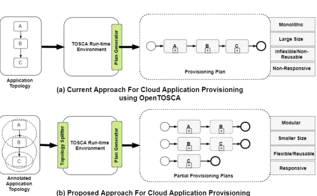
1.1 Illustration to demonstrate the motivation for the problem statement by com-paring the current approach for Application Provisioning using OpenTOSCA
with the proposed approach . . . 15
1.2 Illustration to demonstrate a sample use case using an application deploy-ment scenario in a multi-cloud environdeploy-ment . . . 17
2.1 Illustration of the components of the NIST Cloud Model (Based on the illustration in [SAMT14]) . . . 21
2.2 Structural Elements of a Service Template and their Relation (Based on the illustration in [TOSCAb13] . . . 24
2.3 Sample Architecture and Processing Flow of the TOSCA Environment (Based on the illustration in [TOSCAb13] . . . 27
2.4 Architecture and Control Flow of the OpenTOSCA Ecosystem (Based on the illustration in [OTOSCa] . . . 29
2.5 Structural components of an Executable BPEL Process Document . . . 32
2.6 Illustration showing the Lifecycle of an Executable BPEL Process . . . 33
2.7 Illustration depicting the classification of Topology Splits . . . 35
2.8 Illustration showing the difference between Vertical and Horizontal Topology Splits . . . 35
3.1 Illustration showing the steps of Plan generation as discussed in [BBK+14] . 43 3.2 Illustration showing the steps of Scale-Out Plan generation as discussed in [KBL17] . . . 45
4.1 Illustration depicting the High Level Concept proposed in the thesis for Dynamic Provisioning of Cloud Applications . . . 49
4.2 Illustration depicting the High Level System Architecture for the concept introduced in Section 4.1 . . . 50
4.3 Syntactic consistency between property and parameter names for a simple topology that deploys a Docker Container on a pre-configured Docker Engine 52 4.4 Illustration showing an Application Template and its components - Topology, Split Definitions, Partial Plans, and Orchestration Map . . . 58
4.5 Illustration showing high-level steps in the Topology Splitting algorithm. . . 59
4.6 Illustration showing the stages involved in the second step of the Topology Splitting algorithm - "Split Topology Vertically" . . . 61
4.7 Illustration showing the stages involved in the third step of the Topology Splitting algorithm - "Split Topology Horizontally" . . . 63
4.9 Illustration showing an Orchestration Map that contains the mapping be-tween Nodes, Split Definitions, and Partial Plans . . . 70 4.10 Illustration showing the different stages of the Partial Plan Orchestration
Algorithm. . . 70 5.1 Illustration showing the sample application topology considered for the
prototype . . . 73 5.2 Illustration showing the Low-Level Architecture for the concepts based on
OpenTOSCA as discussed in [KEP13][KBL17] . . . 75 5.3 Illustration showing the UML class diagram for the CSAR model and
Topol-ogy model used in the prototype implementation (based on the data model in [KEP13]) . . . 77 5.4 Illustration showing the Low-Level Architecture for the concepts based on
OpenTOSCA as discussed in [KEP13][KBL17] . . . 78 5.5 Illustration showing the Low-Level Architecture for the concepts based on
OpenTOSCA as discussed in [KEP13][KBL17] . . . 80 5.6 Illustration showing the Low-Level Architecture for the concepts based on
4.1 Check Topology For User Defined Splits . . . 60
4.2 Split Topology Vertically . . . 62
4.3 Extract Vertical Splits . . . 64
4.4 Check Node Dependency . . . 65
4.5 Check Property Dependency . . . 65
4.6 Generate Split Definition . . . 66
4.7 Remove Duplicate Split Definitions . . . 66
4.8 Split Topology Horizontally . . . 67
4.9 Generate Partial Plans . . . 69
BPEL Business Process Execution Language. 14 BPMN Business Process Model and Notation. 14 CSAR Cloud Service Archive. 14
DSL domain specific language. 14 EPP Executable Provisioning Plan. 43 EPR Endpoint Reference. 31
IA Implementation Artifact. 30 IaaS Infrastructure as a Service. 13 MDD Model Driven Development. 19 OS operating system. 13
PaaS Platform as a Service. 13 PBD Pattern Based Development. 20 POG Provisioning Order Graph. 43 PPS Provisioning Plan Skeleton. 43 QoS quality of service. 13
SaaS Software as a Service. 13
TOSCA Topology and Orchestration Specification for Cloud Applications. 14 VM virtual machine. 13
Cloud Computing, in recent years, has gained widespread popularity within the IT industry because of the lucrative economic benefits it has to offer and the technical ease and flexibility it provides for IT operations and management. Features of the paradigm such as high scalability, high availability, and pay-as-you-go pricing models[MG11] have led to a significant shift in the way today applications are developed and deployed. To add to that, the various service models of the cloud paradigm like Infrastructure as a Service (IaaS), Platform as a Service (PaaS), and Software as a Service (SaaS) [MG11] have further enabled the ease of development and deployment of complex applications within a short span of time. Thereby, providing companies a competitive edge by significantly reducing the time to value and time to market for their products.
As a result of the increasing adoption of the cloud computing paradigm and the ever-growing scale and complexity of the applications that it supports, it has become imperative to automate their provisioning and management processes. Provisioning, in the present context, means providing requested cloud resources to the user on demand. Under the hood, this may involve orchestrating several complex executable steps and managing different files to provision the resource successfully. E.g., provisioning an instance of a simple cloud-based java web-application in an IaaS scenario may involve the following steps - (i) create a virtual machine (VM), (ii) install an operating system (OS), (iii) setup the necessary Java Runtime Environment, and (iv) deploy the web archive file (WAR) file. Manually handling these steps would be not only time-consuming but also prone to human errors. Therefore, automatic provisioning of cloud applications has been one of the focus areas for research in academia as well as the industry.
Traditionally, mostly the cloud providers needed to automate their internal management processes to achieve the necessary quality of service (QoS) for their offerings [BBK+13]. E.g., provisioning a new VM or setting up a PaaS environment like Amazon Beanstalk1.
However, today, automation of provisioning is a necessity in modern-day applications built for the cloud owing to their ever-growing scale and complexity. These applications are typically comprised of several components and may consume services from different cloud providers. Moreover, the deployment strategies of these applications may vary based on business requirements. E.g., the front-end of a web application may be outsourced on to a Public Cloud like Amazon AWS2, whereas the backend is deployed on a Private
Cloud within the premises of the company. These factors further add to the complexity
1https://aws.amazon.com/elasticbeanstalk/ 2https://aws.amazon.com/
of the provisioning process. An attempt to manually deploy such applications would require extensive technical know-how of the various proprietary interfaces exposed by cloud vendors and their corresponding data exchange formats [BBK+13]. Moreover, the tight coupling between the application and the cloud service providers may further result in the so-called vendor lock-in problem that affects the portability of the application in a multi-cloud environment [OST16]. A multi-cloud environment provides the possibility of provisioning an application across multiple cloud service providers and multiple cloud offering e.g., Private clouds and Public clouds.
Several configuration management tools have been developed, in recent years, to tackle the problem of automatic application provisioning and deployment, like CHEF3, Puppet4, Ansible5, and Saltstack6. These tools use proprietary domain specific languages (DSLs) to specify the provisioning and management steps for the applications declaratively. These steps are then converted into executable code that are orchestrated (e.g., using workflows) to provision the application successfully. Additionally, AWS Cloud Formation7is a
propri-etary orchestration based cloud application provisioning service offered by Amazon. It works similarly as the configuration management tools discussed above, but it lets the users define only AWS resources (EC28, or S39 Buckets) using its JSON compliant DSL.
Although these tools solve a part of the problem by automating the provisioning process, they do not address the issue of application portability in a multi-cloud environment or the interoperability of the provisioning specifications that are represented by the proprietary domain specific languages.
Therefore, to address the issues mentioned above, the Topology and Orchestration Spec-ification for Cloud Applications (TOSCA) [TCATTC] standard was introduced. "TOSCA is an OASIS open standard that defines the interoperable description of services and ap-plications hosted on the cloud and elsewhere; including their components, relationships, dependencies, requirements, and capabilities, thereby enabling portability and automated management across cloud providers regardless of underlying platform or infrastructure; thus expanding customer choice, improving reliability, and reducing cost and time-to-value" [OTTC]. TOSCA enables the description of cloud applications as XML [BPS+08] based definition files. These definition files define the overall structure and dependencies between the various components of the application. The structure of the application is defined by a so-calledTopology. The definition files also contain information regarding the artifacts e.g., WAR files, VM images, and shell scripts that are required to install the various components of the application. The provisioning logic in TOSCA is specified in the form of so-called Plansthat can be workflows implemented using Business Process Execution Language (BPEL) (2.5) or Business Process Model and Notation (BPMN) [OMG11]. All the definition
3https://www.chef.io/chef/ 4https://puppet.com/ 5https://www.ansible.com/ 6https://saltstack.com/ 7https://aws.amazon.com/cloudformation/ 8https://aws.amazon.com/ec2/ 9https://aws.amazon.com/s3/
files, the artifacts, and the plans are then packaged into an archive file called Cloud Service Archive (CSAR). The CSAR file can then be deployed to any environment that supports a TOSCA compliant run-time engine, thereby making the application portable as well as inter-operable.
Since its introduction, many TOSCA based solutions have been developed for cloud apli-cation provisioning and management. One such implementation is OpenTOSCA10.
Open-TOSCA is an open source Open-TOSCA compliant ecosystem that provides the end-to-end tools chain to model, provision, and manage cloud applications. The OpenTOSCA runtime supports both Imperative and Declarative processing of application management logic [BBK+14]. For the scope of this thesis, we will limit our discussion to the later. Declarative processing, in the context of the TOSCA standard, refers to the automatic provisioning by interpreting the topology of the application embedded in one the definition files that are packaged in the CSAR. Declarative processing, in OpenTOSCA is supported by the Plan Generator component of the runtime environment that generates BPEL plans for the provisioning and management of the application.
1.1 Problem Statement
Figure 1.1:Illustration to demonstrate the motivation for the problem statement by com-paring the current approach for Application Provisioning using OpenTOSCA with the proposed approach
As mentioned in the previous section, the Plan Builder component of the OpenTOSCA runtime automatically generates BPEL plans by interpreting the application structure and its dependencies from the definition files packaged in the CSAR. Although, this approach aids in solving the problem of automatic provisioning of cloud applications, in its current form, it suffers from a few drawbacks highlighted next.
• Firstly, the BPEL plans generated are monolithic, i.e., the plan builder creates a single plan to provision the entire application including all of its components. As a result of which, with the increase in complexity and size of the cloud application, the complexity and size of the BPEL plan also increases significantly.
• Secondly, execution of BPEL plans in a compliant execution engine like Apache ODE, or WSO2 BPS can be a time and resource-intensive process. Therefore, having large and complex plans may further result in performance overload in situations where the available computing resources are limited, e.g., in IoT devices like Raspberry Pi. • Thirdly, the plans generated by the plan builder are tightly coupled to the application,
i.e., the plans are not generic and therefore cannot be reused for provisioning other applications [BBK+14].
• Finally, OpenTOSCA, in its current form, does not support dynamic provisioning. Dynamic provisioning refers to the ability of the service/application provider to provide resources to the user at runtime. The plans generated by the plan builder only allow for provisioning instances of the complete application. They do not support provisioning parts of the application during runtime which affects the flexibility of the system in a dynamic and scalable environment.
The purpose of this thesis is to explore the possibility of provisioning an application using multiple modular plans instead of a single monolithic plan. This in turn would provide a possible approach to alleviate some of the problems mentioned above that are related to monolithic plans while also acting as a proof of concept for the more complex issue of dynamic provisioning in OpenTOSCA.
1.2 Motivating Scenario
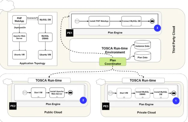
In order to motivate the problem statement, let us consider a simple cloud application as depicted by the Topology in Figure 1.2. The application comprises a PHP Web Application deployed on an Ubuntu VM with an Apache Web Server installed on it. The PHP Application in turn connects to a MySQL DB that is deployed on an Ubuntu VM with a MySQL RDBMS installed on it. Based on the business requirements, it is assumed that the PHP Web Application will be deployed on aPublic Cloud, while the database will be deployed on a Private Cloudfor data security. Moreover, the provisioning of the application is handled by a TOSCA run-time environment (e.g. OpenTOSCA) managed by a third party as shown in the figure.
Figure 1.2:Illustration to demonstrate a sample use case using an application deployment scenario in a multi-cloud environment
Traditionally, the TOSCA run-time environment would generate a single plan for the application topology. The plan would then be deployed on the local plan engine (PE1, Figure 1.2) and the tasks will be orchestrated to provision the complete application. But the drawbacks of such an approach has already been detailed in the previous section (1.1). In this example, we consider that the run-time engine is capable of generating modular plans as labeled 1-3 in the figure. These plans are then deployed to the respective environments, e.g. Plan-1, that installs a database on a VM is deployed to PE-3 on the private cloud. Whereas, Plan-2, that installs an Apache Web Server on a VM is deployed to the plan engine (PE-2) of the public cloud. A third plan (P3) that installs a PHP Web Application and connects it to the installed Database instance, is deployed locally at PE1. Then, the Plan Coordinator component of the TOSCA run-time engine orchestrates the modular plans in order to create an instance of the complete application.
1.3 Scope of Work
This Master Thesis deals with the process of generation of modular plans for a given application followed by their orchestration for the successful provisioning of the application in TOSCA. The main contribution of this thesis is the development of an abstract concept for achieving the above mentioned goal. The feasibility of the concept is also shown with the
help of a prototype developed within the OpenTOSCA framework using the OpenTOSCA container APIs.
1.4 Thesis Outline
This master thesis is structured as follows:
Chapter 1 – Introduction: The motivation for the thesis is explained with a basic intro-duction of the TOSCA standard and OpenTOSCA ecosystem. The problem statement of the thesis is discussed and the scope of the thesis is also outlined.
Chapter 2 – Fundamentals The important terms and technologies are discussed that are necessary to understand the concepts introduced in the thesis.
Chapter 3 – Related Work The various research work related to cloud application provi-sioning and management, application topology splitting, and generation of scale-out plans in TOSCA are discussed.
Chapter 4 – Concept and Specification The high-level concepts behind the thesis are explained. The general architecture of the approach is outlined and the building blocks are discussed in detail.
Chapter 5 – Design and Implementation The low-level implementation of the concepts and the design of each individual components are described.
Chapter 6 – Conclusion and Future Work In this chapter, a summary of the results of the work is presented as well as an outlook for future work is provided.
In this chapter, we discuss the various terms and technologies that are necessary for the better understanding of the concepts introduced in the thesis. In Section 2.2 we take a look at the cloud computing paradigm and elaborate on its various features followed by a brief overview of the OASIS TOSCA standard in Section 2.3. Then in Section 2.4 we discuss the various components of the OpenTOSCA runtime engine with a focus on the Plan Generator component that is augmented by the concepts introduced in Chapter 4. Finally in Section 2.5 we highlight the essential features of WS-BPEL 2.0 that provide a language for the specification of Executable and Abstract business processes and is used by the OpenTOSCA runtime to generate executable plans.
2.1 Important Terms
Provisioning Provisioning, in general, can be defined as the process of making some-thing available. It is the fourth step in the Operations, Administration, Maintenance and Provisioning (OAMP)1management framework. Provisioning can be defined as the config-uration and deployment of heterogeneous IT resources. Specifically, cloud provisioning can be described as the configuration, management, and deployment of cloud resources to deliver a cloud application to the user.
Orchestration Orchestration is a term found in close association with Provisioning and can be defined as the automated arrangement, management, and coordination of complex software systems. In the context of cloud computing, orchestration can be viewed as the process of defining the architecture of the service, binding software and hardware components, and finally automating and coordinating workflows to deliver the service.
Service Bus Service Bus is a software component that implements the communication between heterogeneous software systems in a Service Oriented Architecture (SOA).
1The OAMP management framework describes the processes, activities, tools, and standards involved in
Model Driven Development (MDD) It is a software development paradigm supported by the Model-driven Architecture (MDA) methodology, a software design approach released by the Object Management Group (OMG) [OMG14]. MDA provides a set of guidelines for structuring specifications expressed as models. It starts with a platform-independent model (PIM), continuing through an appropriate domain-specific language (DSL), and then trans-forming into one or more platform-specific models (PSMs) for the actual implementation platform, e.g., Java™ 2 Platform or.Net, implemented in a general programming language such as Java™, C#, and Python. MDD primarily focuses on Model Transformations and Code Generation. [Yu06].
Pattern Based Development (PBD) It is a software development paradigm that uses accepted solutions to recurring problems within a given context (pattern). Patterns encap-sulate a designer’s time, skill, and knowledge to solve a software problem. By designing around a particular design pattern, developers have greater flexibility to control the gener-ated code, which may be a constraint of MDD. [Yu06]
2.2 Cloud Computing
The National Institute of Standards and Technology (NIST) has defined Cloud Computing as follows, "Cloud computing is a model for enabling ubiquitous, convenient, on-demand network access to a shared pool of configurable computing resources (e.g., networks, servers, storage, applications, and services) that can be rapidly provisioned and released with minimal management effort or service provider interaction" [MG11]. As illustrated in Figure 2.1, The NIST model of Cloud computing is further comprised of (i) five essential characteristics, (ii) three Service Models, and (iii) four Deployment Models. We will discuss these in details in the subsequent sections.
2.2.1 Characteristics
The NIST Model defines five essentials characteristics of cloud computing as listed below, 1. On-Demand Self Service: "A consumer can unilaterally provision computing
capa-bilities, such as server time and network storage, as needed automatically without requiring human interaction with each service provider." [MG11]
2. Broad Network Access: "Capabilities are available over the network and accessed through standard mechanisms that promote use by heterogeneous thin or thick client platforms (e.g., mobile phones, tablets, laptops, and workstations)." [MG11]
3. Resource Pooling: "The provider’s computing resources are pooled to serve multiple consumers using a multi-tenant model, with different physical and virtual resources dynamically assigned and reassigned according to consumer demand. There is a sense of location independence in that the customer generally has no control or knowledge
Figure 2.1:Illustration of the components of the NIST Cloud Model (Based on the illustra-tion in [SAMT14])
over the exact location of the provided resources but may be able to specify location at a higher level of abstraction (e.g., country, state, or datacenter). Examples of resources include storage, processing, memory, and network bandwidth." [MG11] 4. Rapid Elasticity: "Capabilities can be elastically provisioned and released, in some
cases automatically, to scale rapidly outward and inward commensurate with de-mand. To the consumer, the capabilities available for provisioning often appear to be unlimited and can be appropriated in any quantity at any time." [MG11]
5. Measured Service: "Cloud systems automatically control and optimize resource use by leveraging a metering capability at some level of abstraction appropriate to the type of service (e.g., storage, processing, bandwidth, and active user accounts). Resource usage can be monitored, controlled, and reported, providing transparency for both the provider and consumer of the utilized service." [MG11]
2.2.2 Service Models
The NIST Model defines three Service Models for cloud computing as described below, 1. Infrastructure as a Service (IaaS):In this service model, the service provider
ab-stracts the management of the underlying cloud resources such as servers, storage, network through virtualization. The consumers are capable of provisioning funda-mental resources such as VMs, OS, storage, and networks which they can deploy and run their applications. Amazon AWS2, Microsoft Azure3, and Google Cloud Platform4 are some of the popular IaaS providers.
2. Platform as a Service (PaaS):Unlike IaaS that provides virtualized infrastructure to the consumers, this service model provides complete software platforms and runtime environments. The consumers are capable of deploying applications developed using different languages, libraries, services, and tools that are supported by the provider. The consumer has no control over the underlying cloud infrastructure. Some examples of PaaS solutions are Amazon Beanstalk5, Google App Engine6, and Heroku7.
3. Software as a Service (SaaS): This is one of the most commonly found service model in use today for consumer applications. In this service model, the consumers are capable of using a provider’s application deployed on the provider’s infrastructure. Some of the commonly found SaaS solutions are Google Docs8, Office 3659etc.
2.2.3 Deployment Models
The NIST Model defines four Deployment Models for cloud computing as listed below, 1. Private Cloud: In this deployment model, "the cloud infrastructure10 is provisioned
for exclusive use by a single organization comprising multiple consumers (e.g., business units). It may be owned, managed, and operated by the organization, a third party, or some combination of them, and it may exist on or off premises." [MG11]
2https://aws.amazon.com/ 3https://azure.microsoft.com/ 4https://cloud.google.com/ 5https://aws.amazon.com/elasticbeanstalk/ 6https://cloud.google.com/appengine/ 7https://www.heroku.com/ 8https://www.google.com/docs/about/ 9https://www.office.com/
10A cloud infrastructure is the collection of hardware and software that enables the five essential characteristics
of cloud computing. The cloud infrastructure can be viewed as containing both a physical layer and an abstraction layer. The physical layer consists of the hardware resources that are necessary to support the cloud services being provided and typically includes server, storage, and network components. The abstraction layer consists of the software deployed across the physical layer, which manifests the essential cloud characteristics. Conceptually the abstraction layer sits above the physical layer.[MG11]
Considering the pool of resources are privately owned by a single organization it offers higher control, security, as well as data privacy.
2. Public Cloud: This is one of the most commonly found deployment models today. In this model, "the cloud infrastructure is provisioned for open use by the general public. It may be owned, managed, and operated by a business, academic, or government organization, or some combination of them. It exists on the premises of the cloud provider." [MG11]
3. Community Cloud: In this model, a group of organizations gets exclusive usage rights on the provisioned cloud infrastructure. These organizations may have shared concerns like mission, security requirements, policy, and compliance considerations. It may exist on or off premise and can be owned by one of the organizations of the community, a third party, or a combination of them.
4. Hybrid Cloud:In this deployment model,"The cloud infrastructure is a composition of two or more distinct cloud infrastructures (private, community, or public) that remain unique entities, but are bound together by standardized or proprietary technology that enables data and application portability (e.g., cloud bursting for load balancing between clouds)." [MG11]
2.3 OASIS TOSCA
The Topology and Orchestration Specification for Cloud Applications (TOSCA) [TCATTC] is an official standard introduced by the Organization for the Advancement of Structured Information Standards (OASIS) consortium. The goal of the standard was to address the growing complexity of Cloud applications and enable a standardized way to design and manage the applications in a portable and inter-operable manner [TOSCAa13]. In the subsequent sections, we discuss the various concepts and components of the TOSCA specification that are most relevant to the understanding of the concepts presented in the Chapter 4 and 5
2.3.1 Structure
The TOSCA specification is an XML based meta-model for defining IT services [TOSCAa13]. It defines both the structure of the service as well as the necessary definitions of the operations for the management of such services [ZBL17]. The structural components of the metamodel (Figure 2.2) are discussed below. It should be noted that some of the components, e.g., Capability and Requirement Definitions, have been omitted from Figure 2.2 for clarity. Moreover, these components are not necessary for the understanding of the concepts in this thesis.
Figure 2.2:Structural Elements of a Service Template and their Relation (Based on the illustration in [TOSCAb13]
Definitions Document A definition document is the most fundamental unit of the TOSCA specification. It is an XML file that encapsulates all the elements needed to define the Service Template for the application e.g. Node Templates, Relationship Templates, Note Type, Relationship Type, etc. A service template also needs to be defined within a definitions document.
Service Template A service is defined by definitions document named Service Template. The service template provides the end to end information that is necessary to create and manage instances of the service in the cloud. The two primary components of the Service Template are the Topology Template and Plans. The Topology Template defines the structure and components of the service, and the Plans define processes that are necessary to deploy, manage, and terminate the service during its lifetime.
Topology Template The Topology Template is a directed graph (not necessarily con-nected) comprising of nodes and edges. The nodes are represented byNode Templates which in turn represent a component of the application, e.g., a PHP application, a Docker container, or a virtual machine. The edges in the Topology Template are represented by Relationship Templateswhich further represent the dependencies between the various Node Templates, e.g., hostedOn, dependsOn or connectsTo.
Node Types and Relationship Types Furthermore, the TOSCA standard promotes re-usability of the Node Templates and Relationship Templates through Node Types and Relationship Types which are used to define the semantics of the node and relationship templates respectively [TOSCAa13]. The Node Types defineProperties, e.g. credentials for a database node, andOperationse.g. ‘CreateVM’, ‘StartVM’, ShutdownVM viaInterfaces for a VM node. The same semantics hold for Relationship Types as well.
Implementation Artifacts and Deployment Artifacts The management operations de-fined within interfaces in the Node and Relationship Types are implemented by artifacts called Implementation Artifacts (IA). They can either be simple Shell Scripts or may be packaged into WAR files. Then, there are some artifacts that implement the business logic of a given node and are represented by Deployment Artifacts (DA). For example, an image file to instantiate a VM or a Node JS script implementing a simple application.
Plans Additionally, the Topology Templates defined in the Service Templates are instanti-ated using special plans referred to as build plans. These plans defined within the Service Template facilitate the automated management of the application. Based on the activity performed, these plans can broadly be categorized as (i) build plans, (ii) management plans, and (iii) termination plans. These plans orchestrate the management operations defined in the node/relationship types and templates to provision, manage, and terminate instances of the application respectively. TOSCA does not specify a particular process modeling language for the definition of plans, however, recommends to use a workflow language such as the Business Process Execution Language (BPEL) for the Advancement of Structured Information Standards (OASIS) [BPEP07] the Business Process Model and Notation (BPMN) [OMG11].
CSARs Further, TOSCA ensures the portability of applications by packaging the Ser-vice Templates, type definitions, artifacts and management plans necessary to provision the application into a self-contained archive file called Cloud Service Archive (CSAR). This archive can be executed by all standard-compliant TOSCA Runtime Environments, e.g., OpenTOSCA (Binz et al.,2013), and, thus, ensures the application’s portability and interoperability.
2.3.2 Processing Environment
A TOSCA environment, offered by a Cloud Provider, may contain a set of features that are necessary to process the definitions according to the specification [TOSCAb13]. These features can be grouped into various logical components that in turn are grouped to define the architecture of the TOSCA environment. Moreover, different service providers may choose to include some or all the features in their respective offerings thereby resulting in different TOSCA architectures. A sample architecture is depicted in Figure 2.3 and its components and processing steps are discussed in the following section for a general understanding of the TOSCA processing environment.
To begin with, a (graphical)TOSCA Modeling Toolis used to create CSAR files that package the cloud application to be provisioned. Even though this is an optional component, its use is recommended.
Once, the CSAR is created, it can either be processed (i) imperatively, or (ii) declaratively. Imperative Processingrequires that the service template contains the complete topology of the cloud application, and also all of its management behaviors is explicitly defined using plans. On the other hand,Declarative Processingassumes that it is possible to extract the management behavior of the cloud application from its topology; this requires that the semantics of the node types and the relationship types are defined precisely and that the TOSCA environment is capable of interpreting them correctly.
Further, processing in a TOSCA environment can be broadly divided into two stages -(i) CSAR Deployment, and(ii) Application Instance Management. These stages are discussed briefly in the following sections.
CSAR Deployment
In this stage, the CSAR file is processed, all its components are extracted, and the environ-ment for the manageenviron-ment of the cloud application is set up. The process comprises the following steps,
1. The CSAR file is processed by theCSAR Processorsuch that it can be initially deployed into the environment (step 1, Figure 2.3). This component contains the logic to parse the CSAR file correctly based on the semantics proposed by the TOSCA specification. 2. CSAR Processor interacts with theModel Interpretor(in the case of Declarative Process-ing) to determine the management behavior of the application (step 2, Figure 2.3). 3. The CSAR Processor extracts all the definition files from the CSAR and passes them
on to theDefinition Manager(step 3, Figure 2.3). The definitions manager then stores all the definition files in theModel Repositoryto be retrieved and used later (step 4, Figure 2.3).
Figure 2.3:Sample Architecture and Processing Flow of the TOSCA Environment (Based on the illustration in [TOSCAb13]
4. Furthermore, the CSAR processor extracts all the implementation and deployment artifacts and passes them to theArtifact Manager(step 5, Figure 2.3). The artifact manager then stores them in the appropriateArtifact Store(step 6, Figure 2.3), e.g,. storing Virtual Images in virtual image directories, or Docker images in a Docker Repository, etc.
5. Next, the Deploy Manager deploys all the implementation artifacts into the envi-ronment thus making the executables for all the operations of the node types and relationship types available and ready for use (step 7a, Figure 2.3).
6. In case of imperative processing, Step-2 above is skipped, and an additional step is added at the end. In this step, all the plans available within the CSAR are deployed into the Process Engine (step 7b, Figure 2.3). Deploying a plan includes binding the tasks in the plan to the concrete endpoints in the environment which host the operations of the node and relations via the deployed implementation artifacts.
Application Instance Management
Once the environment is set up after the successful deployment of the CSAR, instances of the cloud application can be created, updated, and terminated. The possible steps in this process are listed below,
1. The process of instance creation is handled by theInstance Manager (step A, Fig-ure 2.3)
2. It can be done by either invoking deployed Build Plans in the Process Engine in case of imperative processing (step B, Figure 2.3), or by interacting with the Model Interpreter in case of declarative processing (step B’, Figure 2.3)
3. The instances of the application and its components are stored in theInstance DB. 4. Once the instance of the applications are created, the applications can be managed by
calling the respectiveManagement Plansmentioned in Service Template and deployed in the Process Engine (step C, Figure 2.3) .
5. Finally, when the application is no longer required, it can be decommissioned by either execution the respectiveTermination Planin the Process Engine, or by interacting with the Model Interpreter.
2.4 OpenTOSCA
OpenTOSCA is a TOSCA compliant ecosystem for cloud application modeling, deployment, and management. It is a research prototype developed by the Institute of Architecture of Application Systems (IAAS)11 and the Institute for Parallel and Distributed Systems (IPVS)12 of the University of Stuttgart, Germany. OpenTOSCA comprises of three major
components - (i) Modeling Tool (Eclipse Winery), (ii) Runtime Environment (OpenTOSCA Container), and (iii) Administration and Self-Service Portal (OpenTOSCA UI). Figure 2.4 depicts the architecture and control flow of the ecosystem. It can be seen that OpenTOSCA architecture builds on top of the sample TOSCA environment architecture in Figure 2.3. For this thesis an overview of the OpenTOSCA Container is sufficient. However, for the sake of completeness, we provide a brief overview of the other components as well.
2.4.1 Eclipse Winery
Winery is an open source TOSCA Modeling tool [KBBL13]. It provides a UI for modeling Topology Templates and packaging them into CSARs. Winery also provides a management
11http://www.iaas.uni-stuttgart.de/ 12https://www.ipvs.uni-stuttgart.de/
Figure 2.4:Architecture and Control Flow of the OpenTOSCA Ecosystem (Based on the illustration in [OTOSCa]
backend to manage types and artifacts. It also facilitates the import and export of CSARs thereby enabling the creation of new CSARs, and modification of existing ones.
2.4.2 OpenTOSCA UI
The OpenTOSCA UI is a web application developed in NodeJS that combines two features -(i) the Admin UI, and (ii) the Self-Service Portal (formerly known as Vinothek). The Admin
UI is used to upload and install a CSAR into the runtime environment, and the Self-Service Portal is used to instantiate, monitor, and manage application instances for the deployed CSARs. The UI interacts with the container via the OpenTOSCA Container API.
2.4.3 OpenTOSCA Container
"The OpenTOSCA Container is the TOSCA Runtime Environment to deploy and manage Cloud applications. It enables the automated provisioning of applications that are modeled using TOSCA and packaged as CSARs" [OTOSCb]. The implementation of the OpenTOSCA container is based on the OSGi framework [OSG08] thereby ensuring extensibility of its
components. As shown in Figure 2.4,Control, IA Engine, Core, Service Invoker, and Plan Engineform the core components of the OpenTOSCA container. TheContainer API is used by external components to interact with the container via well-defined REST endpoints. The requests to the API are passed to the control component which manages and orchestrates the other components of the runtime. The Core component offers common services to other components, e. g., managing data or validating XML.
Similar to the concept discussed in (2.3.2), processing in OpenTOSCA can also be broadly divided into two stages - (i) CSAR Deployment, and (ii) Application Instance Management, that are briefly discussed in the following sections.
CSAR Deployment
Once the CSAR is uploaded using the OpenTOSCA UI, the Container API is used to deploy the application into the OpenTOSCA Environment. The following steps outline the control flow of the CSAR deployment process [BBH+13],
1. First, theControlcomponent unpacks the CSAR, processes the files, and then store them into theFile Store.
2. Next, all the TOSCA definition documents (XML files) are loaded, validated for proper semantics, and processed by the Control component. Once verified, these definitions are stored in theModelrepository.
3. The control component then calls theImplementation Artifact (IA) Engine. The IA engine deploys the implementation artifacts referenced in the definition files, e.g., SOAP Web Services implemented as WAR files through a supported plugin into a compatible runtime. OpenTOSCA uses an Apache Tomcat server as IA Runtime for WAR files. Once the plugin has successfully deployed the IA and returned the endpoints of the corresponding management operations, the IA Engine stores them in theEndpointsdatabase.
4. Next, thePlan Enginechecks for available plans within the service template (imper-ative processing) and processes them. The Plan Engine employs plugins that can support different workflow languages like BPEL or BPMN and their corresponding runtime environments. Presently OpenTOSCA supports BPEL workflows and uses WSO2 BPS13as itsPlan Runtime.
5. In case, no plans were found in step 4, the Plan Engine generates the plans from the given topology template (declarative processing) and then deploys the generated plans to the Plan Runtime.
Application Instance Management
Once the CSAR is deployed and the environment is setup successfully, the life-cycle of the application can be managed using the OpenTOSCA UI. The following steps outline the control flow of the process [BBH+13],
1. Upon receiving a request to create an instance of the application, the Container API passes it to the Control component which in turn forwards the request to the Plan Engine.
2. The Plan Engine then invokes the respective Build Plan to provision the application instance. The plans use thePlan Portability APIto access the Topology and Instance values, e.g., node and relationship property values.
3. Application management (e.g., scaling) and decommissioning are handled similarly by invoking the corresponding Management Plans and Termination Plans respectively.
2.5 OASIS WS-BPEL 2.0
WS-BPEL stands for Web Services Business Process Execution Language. It provides a model and the semantics for orchestration of Business Processes using web-services [BPEP07]. The basic concepts of WS-BPEL can be applied in one of the two ways - (i) abstract, and (ii) executable. For the scope thesis, only Executable BPEL Processes will be considered.
Executable Processes can be deployed into a compatible Process Engine (e.g., WSO2 BPS) where they execute and interact with their partners in a consistent way through Web Service resources and XML data. For all purposes of discussion, hereon, the terms Plan, BPEL Process, and Executable Business Process will be used interchangeably. In the following section, we will briefly discuss the relevant aspects of the (i) structure and (ii) lifecycle of an executable BPEL Process.
2.5.1 Structure
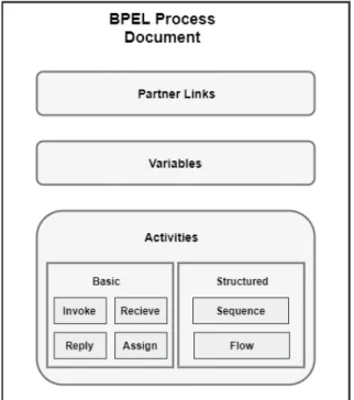
As depicted in Figure 2.5, a BPEL Process document comprises of the following components - (i) Partner Links, (ii) Variables, (iii) Correlation Sets, and (iv) Activities. It should be noted that the list of components is not exhaustive and certain components have been omitted for clarity.
Partner Links At an abstract level, partner links define the shape of the communication between the business process and a partner. They are further typed by the so-calledPartner Link Types. Partner link types characterize the relationship between two services by defining
Figure 2.5:Structural components of an Executable BPEL Process Document the roles played by each of them and specifying theportType14 defined by each service to receive messages within the conversation. However, the concrete services provided by a partner can be dynamically determined using the notion of an Endpoint Reference (EPR) [BPES07].
Variables A variable is the persistent data that is required to maintain the state of the business process, e.g., the messages that are received from the partners, of the messages that are constructed to be sent to the partners. Variables can also hold data that are needed for holding state related to the process and are never exchanged with partners.
Activities In WS-BPEL, Activities are the components that perform the processing logic. They can be broadly categorized into the following two types - (i) Basic Activities, and (ii) Structured Activities.
• Basic Activitiesdescribe the elemental steps of a Business Process behavior. Some of the relevant basic activities are described below,
– Invoke: This activity is used to invoke an operation exposed by a service. It contains the inputVariableandoutputVariableattributes that carry the input and the output messages sent to and received from the invoked operation.
14A WSDL portType is a set of abstract operations along with the abstract messages involved, that are exposed
– Receive: A BPEL process can be instantiated only if it contains areceive(or f low) activity with thecreateInstanceattribute set totrue. It contains avariable attribute that is used to receive the incoming message data. This is a blocking activity and does not complete unless a matching message is received by the instance of the business process.
– Reply: This activity is used to send a response to a request that was previously made using arecieveactivity. This activity is only valid in case of arequest−
reply interaction between the process and the partner(s).
– Assign: This activity is primarily used for data assignments within a BPEL process. An assign activity enables copying of data from one variable into another, as well as constructing and inserting new values.
• Structured Activitiesdescribe the order in which a collection of activities is executed. They describe the creation of a business process by coordinating the control flow, fault handling, and message exchanges using nested activities. Some of the relevant structured activities are described below,
– Sequence:This activity contains one or more nested activities that are executed sequentially. Execution of a sequence activity completes when the last nested activity is successfully executed.
– Flow: This activity contains one or more nested activities that are executed concurrently. Execution of a sequence activity completes when all the nested activities are successfully executed. Af lowactivity may containlinkelements that are used for synchronization of the nested activities.
2.5.2 Lifecycle
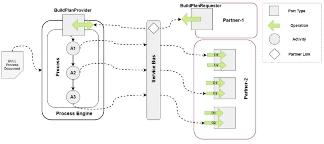
As depicted in Figure 2.6, a lifecycle of a BPEL Process comprises of the following steps - (i) Process Deployment, (ii) Process Instantiation, and (iii) Process Termination. These steps are discussed below,
Process Deployment In this step, first, the BPEL Process Document is deployed in the Process Engine. Then the actual binding information about the partner services is deter-mined dynamically via assignment of endpoint references which contain the information of the Partner Links defined in the Process Document.
Process Instantiation Once the binding information of services is available, an instance of the process can be implicitly created by receiving messages via the Port Types defined for the Partner Role assigned to the process. As discussed in 2.5.1, a Receive activity with createInstanceattribute set totrueinitiates the instance creation for the process.
Process Termination A BPEL Process can terminate in two ways - (i)Normal Termination when the root activity completes execution, or (ii)Abnormal Terminationwhen a fault is encountered or anexitactivity is used explicitly.
2.6 Topology Splitting
An application topology can be split in two ways -physically or conceptually. Therefore, within the context of this thesis,Splitsare broadly classified into the following two cate-gories -Physical Splits and Conceptual Splits. These categories are further classified into two sub-categories viz. Vertical Splits and Horizontal Splits. This classification is depicted graphically in Figure 2.8. For the algorithms presented in Section 4.5.2 and for all purposes of discussion hereon, the termSplitwould refer to aConceptual Splitunless otherwise men-tioned.Moreover, aConceptual Splitis formally represented by aSplit Definition(Definition 4.3.17, Section 4.3.1). A brief description of each category is provided below.
2.6.1 Physical Split vs. Conceptual Split
Physical Splitsas the name suggests, physically alter the given topology. The topology file is split into multiple smaller topology files, each containing a subset of the original topology elements. The split topology files are then iteratively provided as input to the Plan Generator component (4.6) in order to generate the partial plans. These partial plans can then be orchestrated in the correct order to provision the application.
Conceptual Splitson the other hand preserve the original topology file. Instead of gen-erating multiple granular topology files, splits are defined in the same topology file by
Figure 2.7:Illustration depicting the classification of Topology Splits
annotating topology elements similar to [SBKL17] or by definingSplit Definitions(4.3.1). Split definitions are basically meta-data contain the information about individual splits, e.g, the nodes and relations contained within the split. The annotated topology is provided as an input to the the Plan Generator component. The Plan Generator interprets the split definitions to generate the partial plans that are then orchestrated for provisioning the application.
2.6.2 Vertical Splits vs. Horizontal Splits
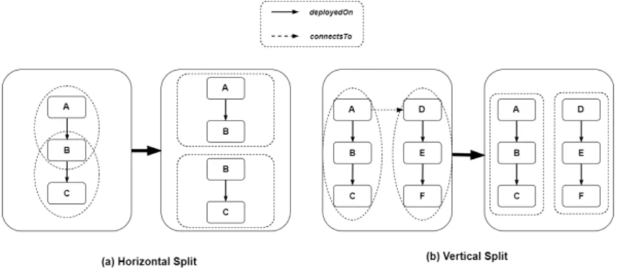
Vertical/Horizontal Splits depend on the relationships within a topology.We primarily consider two base Relationship Types in this thesis -HostedOn and ConnectsTo.
Vertical Splitrefers to a split in the topology across aConnectsToRelationship Type or its derivatives. This is depicted in Figure 2.8(b).
Horizontal Splitrefers to a split in the topology across aHostedOn or DependsOn Relation-ship Type or their derivatives. This is depicted in Figure 2.8(a).
Figure 2.8:Illustration showing the difference between Vertical and Horizontal Topology Splits
In this chapter we discuss the related research work done that is relevant to the concepts presented in this thesis. First, we explore some of the model (3.1) and pattern (3.2) based approaches for provisioning and management of cloud applications, followed by a look at some of the work done in the area of provisioning using the TOSCA standard (3.3). Finally, in Section 3.4 we take a look at a topology splitting and matching technique for deploying applications in a multi-cloud environment. Also, for each of the work discussed, we will highlight their limitations, if any, and also underscore their influences on the work done in this thesis.
3.1 Model Based Provisioning and Management of Cloud
Applications
3.1.1 Pattern-based Composite Application Deployment
Eilam et al. [EEKS11] in the paper titled Pattern-based Composite Application Deploy-ment propose a model-based approach for cloud application deployDeploy-ment by bridging the gap between high-level non-executable deployment models and low-level executable workflows.
Motivation
Deployment methodologies for provisioning composite enterprise applications can be broadly categorized intoworkflow-basedapproaches andmodel-driven design[EEKS11]. Although the workflow based approach is more popular than model-driven approaches, it suffers from high sensitivity to topological changes in the application and design complexity. On the other hand, while the model-driven approach shows promise by providing a high-level of abstraction, separation of concerns, and strong semantics, they suffer from the fact that the output of such a model is not directly executable. Therefore, Eilam et al. in their paper propose a method to integrate both the approaches to provide high flexibility in modeling complex applications while automatically generating reusable workflows to deploy them.
Approach
The proposed approach in [EEKS11], on a high level, comprises of defining adeployment modelthat represents the desired deployment state of an application and then the auto-mated transformation of the model into an executable workflow. The conversion involves two steps - (i) identifying a set of operations which will affect the desired state, and (ii) determining the partial order in which they can be executed. The operations are repre-sented asautomation signatureswhich comprise of a model pattern that describes the effect of the operation on components of the given model, and its requirements on related components. E.g., an operation to install a docker engine on a VM may require the IP address of the VM. Automation signatures, therefore, provide the link between the models and the underlying executable operation logic (implemented as scripts or workflows). The deployment model consists of aTopologythat is used to define the desired state of the application. The Topology further comprises of typednodesandedgesthat represent resources which are to be installed. Furthermore, the operations declare automation signatures that define the requirements of their operation and their effects in a semantically rich manner. An automation signature is represented as a 3-tupleA= (O, P, L)whereO is the Operation,P is a deployment model known aspattern, andLrepresents the set of relations between the Operation and the Pattern.
To generate a workflow for a given deployment model, the problem is modeled as a set cover algorithm. Firstly, all thetargeted nodesare obtained from the model. Targeted nodes are a subset of the deployment model for whichinitstate̸=goalstate. This subset is treated as the universeU. Then, a collectionSis obtained which consists of all possible implementations of automation signatures for the targeted nodes. The algorithm then finds a sub-familyC ⊆S that covers the UniverseU, such that none of the sets inC overlap. Finally, the partial order of the operations inC is found by analyzing the requirements expressed in their automation signatures and incorporating available domain knowledge. Once the partial ordering is obtained, they can be flattened to a total order.
Summary and Influences
The workflow generation algorithms proposed in the paper make use of graph covering techniques to determine the optimal set of operations to instantiate the deployment model. This is done by matching the automation signature patterns with the targeted nodes. We will use a variant of the algorithm in Section 4.5.2 to determine dependencies between different nodes in a topology to group them into logical units calledSplit Definition.
3.2 Pattern Based Provisioning and Management of Cloud
Applications
3.2.1 Pattern-based Deployment Service for Next Generation Clouds
In the paper Pattern-based Deployment Service for Next Generation Clouds Lu et al. [LSS+13] provide a service to deploy a multi-cloud application using deployment plans that are represented in the form of patterns. A pattern represents an abstract view of the cloud application that in turn represents the logical units of the application and their corresponding mapping to the actual cloud resources. The service not only instantiates the pattern but also allows for runtime updates to the deployed application.
Motivation
The Pattern Based Deployment Service (PDS) proposed in [LSS+13] tries to overcome two challenges - (a) automated application deployment on a two-tiered (smart edges and core) as well as the multi-cloud environment, and (b) dynamic adaptation of the deployed application.
Approach
On a high level, the PDS takes as an input aSystem Pattern Description (SPD)file. The SPD defines the details of the application topology and deployment. Once uploaded, the SPD is parsed by the service and a graph is generated that represents the abstract steps required to deploy the application. The generated graph is then dynamically converted into Chef commands which in turn are executed to instantiate the various nodes of the application topology.
The pattern-based deployment service defines its own XML based Domain Specific language (DSL). The DSL identifies the following elements -topology, container, node, and service. Thetopologyrepresents the structure and relationship between the various components of the application to be deployed. Thecontainerelement represents a collection of nodes. A noderepresents a virtual machine instance that has several attributes that, e.g., define the cloud on which the node will be deployed and the services that should be deployed on the given node. Theserviceelement defines the various software components that should be installed/deployed on a given node.
Moreover, a topology may have multiple nodes, and a node can have multiple services (e.g., Database, Web Application, etc.). This, in turn, may result in a scenario where the deployment of one service may require configuration information from another service and so on. E.g. The web application service on one node may need the IP address of the node that hosts the database service to establish a connection. The paper defines such dependencies asdeployment dependencies. The DPS uses two algorithms to detect and
resolve such dependencies. On a conceptual level, the first algorithm iterates through the topology to extract all the deployment dependencies and the second algorithm defines the correct ordering of the Chef invocations. Finally, a workflow is defined which makes sure that the Chef recipes are executed in the correct order with the right attributes to make sure that the service dependencies are correctly resolved, and the nodes are successfully deployed.
Summary and Influences
As discussed in the previous section, the PDS converts the system pattern (SPD) represented in the form of an XML-based DSL into a workflow of actions. These actions are specific to Chef and their execution in the defined order provisions the application in a multi-cloud/two-tier cloud environment. But, the approach doesn’t talk about granular and reusable workflows (Plans). The workflows generated are monolithic and tightly coupled to the topology defined in the SPD thereby suffering from the drawbacks that were highlighted in Section 1.1.
3.2.2 Pattern-based Runtime Management of Composite Cloud Applications
Breitenbücher et al. [BBKL13] in their paper Pattern-based Runtime Management of Composite Cloud Applications, propose a pattern-based approach to decouple high-level management of cloud applications from their low-level management operations. This, in turn, allows for the re-usability of management knowledge in a dynamic and automated manner for different applications.
Motivation
The paper attempts to tackle the complex task of management of distributed cloud appli-cations. The challenge with such applications is the unavailability of a mapping between the high-level tasks such as scaling-out components of the application and the actual operations that implement the tasks above. As a result, often such management tasks tend to be tightly coupled to the applications while making is hard to reuse the management knowledge for other applications. Therefore, the authors in [BBKL13] define a method in which (i) high level tasks are captured byManagement Patterns, (ii) a separate manage-ment layer, calledManagement Planlets, provide executable low level Management tasks, (iii) both the layers are integrated seamlessly to provide the overall Management of the
Approach
On a conceptual level, the approach for execution of management tasks for distributed cloud applications in an automated manner is divided into three steps - (i) Applying Management Patterns, (ii) generating Management Plans by orchestrating Management Planlets, and (iii) execution of the generated plans.
In the first step, high-level management tasks such as scaling-out an application are mapped to Management Patterns which represent the high-level knowledge required to perform the desired management tasks. These Management patterns transform theApplication State Models (ASM)of a running application to the so-calledDesired Application State Models (DASM). The ASM reflects the current state of an application. It contains the Application Topologywhich is conceptually similar to a SPD (Section 3.2.1) and a Topology (Section 3.1). The Application topology is a graph that represents the components of the application and the relationship among them. The components, in turn, may have arbitrary key-value pairs, e.g., the IP address of a Virtual Machine component, that hold the runtime information about them. The DASM, on the other hand, represents the desired state of the application. It is represented by an annotated topology where the annotations may mean creation, removal of components or execution of domain-specific tasks on the respective component. Further, Management Patterns comprise of primarily two parts -(i) Target Topology Fragment, and(ii) Topology Transformation. The Target Topology Fragment represents a subset of a topology, i.e., components and relationships on which the Management Tasks of the respective pattern will be applied. This fragment is used to match the components of an ASM to the pattern. Once a match has been found, the Topology Transformation is applied to the ASM to generate the DASM.
In the second step, a Management Plan is generated from the DASM obtained from the previous step by the Plan Generator. The paper describes three levels of Management gran-ularity viz. Management Plans, Management Planlets, and Management Operations. Management Plans are Workflows which execute the management tasks in an automated manner. They represent the highest granularity of the management layer, e.g., Migration of an application from a private cloud to a public cloud, and are tightly coupled to the application and its topology. At the second level of granularity is the Management Planlets that are small single entry single exit workflows which implement low-level management tasks such as deploying a docker container on a Virtual Machine, or starting a virtual machine on a public cloud. They provide reusable and self-contained building blocks for generating Management Plans for different applications. These Management Planlets may need various input parameters to execute successfully. These input parameters may be pro-vided by the user or extracted dynamically from the mapped elements of the corresponding ASM and DASM. At the lowest level, the Management Operations, which is provided by the components offer concrete functionalities for management tasks, e.g., copy a file to an operating system. These are the operations that are aggregated by the Management Planlets and orchestrated to execute the Management Plans.
To summarize, the Management Plan is generated by first, finding a set of Management Planlets that execute the operations in the DASM, and then employing a Partial Order Planning (POP) algorithm [POP94] to generate a sequence of execution for the planlets. In the third step, the generated Management Plan is provided with the required input parameters and executed to achieve the Desired Application State.
Summary and Influences
The concepts mentioned in this section have a significant influence on the concepts pro-posed in the thesis. To begin with, a concept similar to the annotation based topology transformation will be used to mark the so-calledSplit Definitions. This annotated topology (identical to a DASM) will then be used by the Plan Engine to generate granular plans from the available sets of generic planlets. Then, these granular plans will be orchestrated to determine the optimum sequence of operation to provision the application.
3.3 Provisioning and Management of Cloud Applications in
TOSCA
3.3.1 Combining Declarative and Imperative Cloud Application Provisioning based on TOSCA
In their paper Breitenbücher et al. [BBK+14] introduce a method of automated provisioning for cloud applications that combines both the declarative and imperative management techniques (Section 2.3.2) based on TOSCA topology models. The paper aims to overcome the drawbacks of both the approaches and benefit from their advantages.
Motivation
As already highlighted in Section 2.3.2, the imperative processing approach enables de-velopers to explicitly define the steps of the provisioning in the form of custom plans. This method provides the application developers with a higher degree of control and facilitates customization of complex management tasks. But, it suffers from two significant drawbacks. One, the process of generating custom plans is labor intensive, expensive and error-prone considering heterogeneous management services need to be orchestrated, and script-centric approaches need to be wrapped, and different data formats need to be handled [BBK+13][EEKS11]. Moreover, the provisioning plans generated are tightly coupled with the corresponding application topology. Any changes to the structure of the topology will require the creation of new plans [EEKS11][BBKL13]. Considering applica-tion topologies can get complicated, this approach is not suitable for every situaapplica-tion. The declarative processing approach, on the other hand, alleviates this problem by automating
the plan generation process. But it too suffers from the following drawbacks - (i) the TOSCA runtime environment must be able to interpret the components and management logic to infer the provisioning logic, and (ii) the degree of customization is lost due to automation. Therefore, the approach proposed by Breitenbücher et al. combines both the approaches thereby automating generation process with the help of aProvisioning Plan Generatorwhile also enabling manual customization and fine tuning of the generated plans.
Approach
Figure 3.1:Illustration showing the steps of Plan generation as discussed in [BBK+14] On a conceptual level, the plan generation process works in three steps. These steps are illustrated in Figure 3.1. In the first step, the Topology Template contained in a CSAR is analyzed and a workflow-language independent Provisioning Order Graph (POG) is generated. Each vertex in the POG represents a task to provision a component (Node or Relationship Template) of the topology template. Each directed edge defines the temporal provisioning order, i.e., the source vertex needs to be processed before the target vertex. In the second step, a language-specificProvisioning Plan Skeleton (PPS)is built based on the POG. The PPS containsEmpty Provisioning Activitiesand therefore is not executable. The vertices in the POG are transformed into Empty Provisioning Activities, and the edges define the control flow between the activities. In the final step, the non-executable PPS is converted into an Executable Provisioning Plan (EPP) by injecting language specific Provisioning Subprocess Templatesfor individual node and relationship templates.
Summary and Influences
The concepts presented in the previous section for the foundation of the Plan Builder component of OpenTOSCA. Further, a modified version of the Plan Builder component will be used to generate scale-out plans in Section 3.3.2 which in turn will be reused in this thesis for creating modular plans.
![Figure 2.1: Illustration of the components of the NIST Cloud Model (Based on the illustra- illustra-tion in [SAMT14])](https://thumb-us.123doks.com/thumbv2/123dok_us/9450426.2819373/21.892.133.769.149.542/figure-illustration-components-cloud-model-based-illustra-illustra.webp)
![Figure 2.2: Structural Elements of a Service Template and their Relation (Based on the illustration in [TOSCAb13]](https://thumb-us.123doks.com/thumbv2/123dok_us/9450426.2819373/24.892.132.762.142.665/figure-structural-elements-service-template-relation-illustration-toscab.webp)
![Figure 2.3: Sample Architecture and Processing Flow of the TOSCA Environment (Based on the illustration in [TOSCAb13]](https://thumb-us.123doks.com/thumbv2/123dok_us/9450426.2819373/27.892.133.758.150.716/figure-sample-architecture-processing-tosca-environment-illustration-toscab.webp)
![Figure 2.4: Architecture and Control Flow of the OpenTOSCA Ecosystem (Based on the illustration in [OTOSCa]](https://thumb-us.123doks.com/thumbv2/123dok_us/9450426.2819373/29.892.135.761.154.617/figure-architecture-control-opentosca-ecosystem-based-illustration-otosca.webp)
![Figure 3.1: Illustration showing the steps of Plan generation as discussed in [BBK+14]](https://thumb-us.123doks.com/thumbv2/123dok_us/9450426.2819373/43.892.133.767.366.504/figure-illustration-showing-steps-plan-generation-discussed-bbk.webp)
