Software Developer’s Manual
Specification Update
August 2004
Document Number: 248699-009
Notice: Intel® Itanium® architecture processors may contain design defects or errors known as errata which may cause the product to deviate from published specifications. Current
intellectual property rights is granted by this document. Except as provided in Intel's Terms and Conditions of Sale for such products, Intel assumes no liability whatsoever, and Intel disclaims any express or implied warranty, relating to sale and/or use of Intel products including liability or warranties relating to fitness for a particular purpose, merchantability, or infringement of any patent, copyright or other intellectual property right. Intel products are not intended for use in medical, life saving, or life sustaining applications.
Intel may make changes to specifications and product descriptions at any time, without notice.
Designers must not rely on the absence or characteristics of any features or instructions marked “reserved” or “undefined”. Intel reserves these for future definition and shall have no responsibility whatsoever for conflicts or incompatibilities arising from future changes to them.
Contact your local Intel sales office or your distributor to obtain the latest specifications and before placing your product order.
Copies of documents which have an ordering number and are referenced in this document, or other Intel literature may be obtained by calling 1-800-548-4725 or by visiting Intel's website at http://developer.intel.com/design/litcentr.
Intel and Itanium are trademarks or registered trademarks of Intel Corporation or its subsidiaries in the United States and other countries. Copyright © 2002-2004, Intel Corporation. All rights reserved.
Revision History ... 5
Preface ... 6
Summary Table of Changes ... 7
Specification Changes... 9
Specification Clarifications... 38
Version
Number Description Date
-009 Added Specification Changes 5-9; added Specification Clarifications 16-22; added Documentation Changes 8-13.
August 2004 -008 Added Specification Changes 2-4; added Specification Clarifications 5-15;
added Documentation Changes 1-7.
October 2003 -007 Added Specification Change 1; added Specification Clarification 1-4. December 2002
-001--006
Changes from previous Software Developer’s Manual Specification Updates were incorporated into version 2.1 of the Intel® Itanium® Architecture
Software Developer’s Manual October 2002.
Preface
This document is an update to the specifications contained in the Affected Documents/Related Documents table below. This document is a compilation of device and documentation errata, specification clarifications, and changes. It is intended for hardware system manufacturers and software developers of applications, operating systems, or tools.
Information types defined in Nomenclature are consolidated into the specification update and are no longer published in other documents.
This document may also contain information that was not previously published.
Affected Documents/Related Documents
Nomenclature
Specification Changes are modifications to the current published specifications for Intel® Itanium® architecture processors. These changes will be incorporated in the next release of the specifications.
Specification Clarifications describe a specification in greater detail or further explain a specification’s interpretation. These clarifications will be incorporated in the next release of the specification.
Documentation Changes include typos, errors, or omissions from the current published specifications. These changes will be incorporated in the next release of the Intel® Itanium® Architecture Software Developer’s Manual.
Title Document #
IIntel® Itanium® Architecture Software Developer’s Manual, Volume 1: Application Architecture
245317-004
Intel® Itanium® Architecture Software Developer’s Manual, Volume 2: System Architecture 245318-004
Intel® Itanium® Architecture Software Developer’s Manual, Volume 3: Instruction Set Reference
Summary Table of Changes
The following tables indicate the specification changes, specification clarifications, or documentation changes that apply to the Intel® Itanium® Architecture Software Developer’s Manual.
.
Specification Changes
No. Page SPECIFICATION CHANGES
1 8 Volume 1: ao bit added to CPUID Register 4
2 8 MCA architecture extensions for supporting data-poisoning events 3 11 LID enhancements
4 11 Extend PALE_CHECK exit options 5 13 Addition of tf instruction
6 17 Removal of requirement for externally connected pins
7 20 Architecture extensions for processor Power/Performance states 8 34 Allow Undefined Behavior for All Must-be-last Instructions 9 35 Addition of PAL_BRAND_INFO
Specification Clarifications
No. Page SPECIFICATION CLARIFICATIONS
1 36 Volume 2: PSR.dt serialization clarification 2 36 Volume 2: Unaligned debug fault clarification
3 36 Volume 3: Clarification on PSR requirements for br.ia/rfi instructions during PSR.is transition
4 37 Volume 3: Added Illegal Operation fault to fnma I-page 5 37 Clarify INTA/XTP definition
6 38 Clarify VHPT insert rules
7 38 Adding FP-readers to support table 8 39 cmpxchg clarifications
9 39 Add Illegal Operation fault
10 40 Non-speculative reference for WBL attribute clarification 11 42 Dirty-bit fault ISR.code clarification
12 43 FC data dependency ordering clarification 13 43 PAL_MC_DRAIN clarification
14 44 Add hint instructions to support table
15 44 Clarify speculative operation fault handler requirements 16 47 Clarify role of PMC.ev bit as implementation-specific
17 47 Relax IA-32 Application Registers Reserved/Ignored checking 18 49 Relax ordering constraints for VHPT walks
19 49 Clarify illegal operation fault behavior for predicated off reserved ops 20 50 Clarify opcode hint fields in encodings
21 51 Clarify speculative operation fault handler requirements 22 52 PAL_CACHE_FLUSH clarification
Documentation Changes
No. Page DOCUMENTATION CHANGES
1 51 Update IA-32 CPUID I-Page 2 57 PAL_BUS_GET/SET_FEATURES fix 3 57 PAL_COPY_PAL update
4 58 Fixing X-Unit text correction
5 58 PAL_CACHE_SHARED_INFO text correction
6 58 PAL_CACHE_FLUSH clarification and minor code sequence fix 7 58 PAL_GET_PROC_FEATURES table fix
8 60 Correct the role of X-resources during MCA 9 61 Clarification on the short format VHPT 10 61 Floating-point correction
11 61 Clarify effect of sending IPI to non-existent processor 12 61 Add a new instruction class
Specification Changes
1.
Volume 1: ao bit added to CPUID Register 4
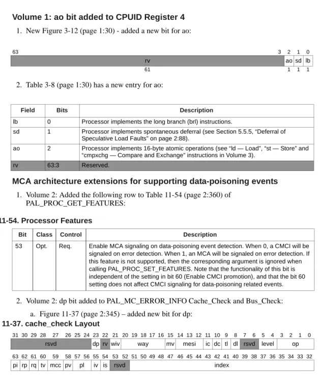
1. New Figure 3-12 (page 1:30) - added a new bit for ao:
2. Table 3-8 (page 1:30) has a new entry for ao:
2.
MCA architecture extensions for supporting data-poisoning events
1. Volume 2: Added the following row to Table 11-54 (page 2:360) of PAL_PROC_GET_FEATURES:
2. Volume 2: dp bit added to PAL_MC_ERROR_INFO Cache_Check and Bus_Check: a. Figure 11-37 (page 2:345) – added new bit for dp:
63 3 2 1 0
rv ao sd lb
61 1 1 1
Field Bits Description
lb 0 Processor implements the long branch (brl) instructions.
sd 1 Processor implements spontaneous deferral (see Section 5.5.5, “Deferral of Speculative Load Faults” on page 2:88).
ao 2 Processor implements 16-byte atomic operations (see “ld — Load”, “st — Store” and “cmpxchg — Compare and Exchange” instructions in Volume 3).
rv 63:3 Reserved.
Table 11-54. Processor Features
Bit Class Control Description
53 Opt. Req. Enable MCA signaling on data-poisoning event detection. When 0, a CMCI will be signaled on error detection. When 1, an MCA will be signaled on error detection. If this feature is not supported, then the corresponding argument is ignored when calling PAL_PROC_SET_FEATURES. Note that the functionality of this bit is independent of the setting in bit 60 (Enable CMCI promotion), and that the bit 60 setting does not affect CMCI signaling for data-poisoning related events.
Figure 11-37. cache_check Layout
31 30 29 28 27 26 25 24 23 22 21 20 19 18 17 16 15 14 13 12 11 10 9 8 7 6 5 4 3 2 1 0
rsvd dp rv wiv way mv mesi ic dc tl dl rsvd level op
63 62 61 60 59 58 57 56 55 54 53 52 51 50 49 48 47 46 45 44 43 42 41 40 39 38 37 36 35 34 33 32
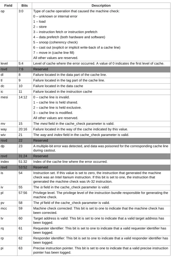
b. Table 11-47 (page 2:345) – added new entry for dp:
Table 11-47. cache_check Fields
Field Bits Description
op 3:0 Type of cache operation that caused the machine check: 0 – unknown or internal error
1 – load 2 – store
3 – instruction fetch or instruction prefetch 4 – data prefetch (both hardware and software) 5 – snoop (coherency check)
6 – cast out (explicit or implicit write-back of a cache line) 7 – move in (cache line fill)
All other values are reserved.
level 5:4 Level of cache where the error occurred. A value of 0 indicates the first level of cache. rsvd 7:6 Reserved
dl 8 Failure located in the data part of the cache line. tl 9 Failure located in the tag part of the cache line. dc 10 Failure located in the data cache
ic 11 Failure located in the instruction cache mesi 14:12 0 – cache line is invalid.
1 – cache line is held shared. 2 – cache line is held exclusive. 3 – cache line is modified. All other values are reserved.
mv 15 The mesi field in the cache_check parameter is valid. way 20:16 Failure located in the way of the cache indicated by this value. wiv 21 The way and index field in the cache_check parameter is valid. rsvd 22 Reserved
dp 23 A multiple-bit error was detected, and data was poisoned for the corresponding cache line during castout.
rsvd 31:24 Reserved
index 51:32 Index of the cache line where the error occurred. rsvd 53:52 Reserved
is 54 Instruction set. If this value is set to zero, the instruction that generated the machine check was an Intel Itanium instruction. If this bit is set to one, the instruction that generated the machine check was IA-32 instruction.
iv 55 The is field in the cache_check parameter is valid.
pl 57:56 Privilege level. The privilege level of the instruction bundle responsible for generating the machine check.
pv 58 The pl field of the cache_check parameter is valid.
mcc 59 Machine check corrected: This bit is set to one to indicate that the machine check has been corrected.
tv 60 Target address is valid: This bit is set to one to indicate that a valid target address has been logged.
rq 61 Requester identifier: This bit is set to one to indicate that a valid requester identifier has been logged.
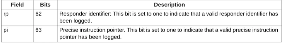
rp 62 Responder identifier: This bit is set to one to indicate that a valid responder identifier has been logged.
pi 63 Precise instruction pointer. This bit is set to one to indicate that a valid precise instruction pointer has been logged.
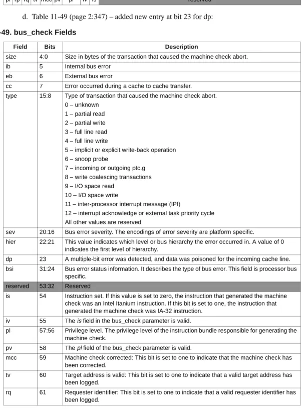
c. Figure 11-39 (page 2:347) – added new bit for dp:
d. Table 11-49 (page 2:347) – added new entry at bit 23 for dp:
Figure 11-39. bus_check Layout
31 30 29 28 27 26 25 24 23 22 21 20 19 18 17 16 15 14 13 12 11 10 9 8 7 6 5 4 3 2 1 0
bsi dp hier sev type cc eb ib size
63 62 61 60 59 58 57 56 55 54 53 52 51 50 49 48 47 46 45 44 43 42 41 40 39 38 37 36 35 34 33 32
pi rp rq tv mcc pv pl iv is reserved
Table 11-49. bus_check Fields
Field Bits Description
size 4:0 Size in bytes of the transaction that caused the machine check abort. ib 5 Internal bus error
eb 6 External bus error
cc 7 Error occurred during a cache to cache transfer. type 15:8 Type of transaction that caused the machine check abort.
0 – unknown 1 – partial read 2 – partial write 3 – full line read 4 – full line write
5 – implicit or explicit write-back operation 6 – snoop probe
7 – incoming or outgoing ptc.g 8 – write coalescing transactions 9 – I/O space read
10 – I/O space write
11 – inter-processor interrupt message (IPI)
12 – interrupt acknowledge or external task priority cycle All other values are reserved
sev 20:16 Bus error severity. The encodings of error severity are platform specific.
hier 22:21 This value indicates which level or bus hierarchy the error occurred in. A value of 0 indicates the first level of hierarchy.
dp 23 A multiple-bit error was detected, and data was poisoned for the incoming cache line. bsi 31:24 Bus error status information. It describes the type of bus error. This field is processor bus
specific. reserved 53:32 Reserved
is 54 Instruction set. If this value is set to zero, the instruction that generated the machine check was an Intel Itanium instruction. If this bit is set to one, the instruction that generated the machine check was IA-32 instruction.
iv 55 The is field in the bus_check parameter is valid.
pl 57:56 Privilege level. The privilege level of the instruction bundle responsible for generating the machine check.
pv 58 The pl field of the bus_check parameter is valid.
mcc 59 Machine check corrected: This bit is set to one to indicate that the machine check has been corrected.
tv 60 Target address is valid: This bit is set to one to indicate that a valid target address has been logged.
rq 61 Requester identifier: This bit is set to one to indicate that a valid requester identifier has been logged.
3.
LID enhancements
1. Volume 2, Part I, Section 5.8.3.1, page 2:104, first paragraph should now read:
“The LID register contains the processor's local interrupt identifier. Two fields (id and eid) serve as the processor's physical name for all interrupt messages (external interrupts, INITs, and PMIs). LID is loaded by firmware during platform initialization based on the processor's physical location within the system. Processors receiving an interrupt message on the system interconnect may or may not compare their id/eid fields with the target address for the interrupt message, depending on the type of system interconnect. If this comparison is performed, then a match would indicate that the interrupt received was intended for this processor. In case of no comparison, processors use other system topology mechanisms to determine the correct target of the interrupt message.”
2. Volume 2, Part I, Section 5.8.3.1, page 2:104, second paragraph, change from: “LID is a read-write register.”
to:
“The LID register fields are read-only or read-write. Details of the programmability of these fields is communicated by PAL at PALE_RESET handoff (see Section 11.2.2: 'PALE_RESET Exit State' for details). Read-only LID bits always return a value of 0. Writes to read-only bits are ignored.”
3. Volume 2, Part I, Section 11.2.2, page 2:259, change the GR33 bullet from:
“GR33 contains the geographically significant unique processor ID. The value is the same as that returned by PAL_FIXED_ADDR”
to:
“GR33 contains information about the geographically significant unique processor ID, and a mask that indicates which bits in the LID register (CR64) are read-only. Firmware should write the processor's local interrupt identifier in the programmable portion of the LID register. Writes to the read-only bits are ignored.
[63:48] Reserved
[47:40] Mask indicating which bits in eid are programmable 0 = programmable, 1 = read-only
[39:32] Mask indicating which bits in id are programmable 0 = programmable, 1 = read-only
[31:16] Reserved
[15:0] Geographically significant processor ID
The value returned in bits [15:0] is the same as that returned by PAL_FIXED_ADDR.”
4.
Extend PALE_CHECK exit options
1. Volume 2, Part I, Section 11.3.1:
a. On page 2:265, first paragraph, change the following sentence from:
“PALE_CHECK terminates by branching to SALE_ENTRY, passing the state of the processor at the time of the error.”
to:
rp 62 Responder identifier: This bit is set to one to indicate that a valid responder identifier has been logged.
pi 63 Precise instruction pointer. This bit is set to one to indicate that a valid precise instruction pointer has been logged.
Table 11-49. bus_check Fields (Continued)
“PALE_CHECK terminates either by returning to the interrupted context or by branching to SALE_ENTRY, passing the state of the processor at the time of the error.” b. In the fifth paragraph change the following from:
“PSR.mc is set to 1 by the hardware when PALE_CHECK is entered. PSR.mc will remain set for the duration of PALE_CHECK, and PALE_CHECK will exit with psr.mc set.”
to:
“PSR.mc is set to 1 by the hardware when PALE_CHECK is entered. When
PALE_CHECK branches to SALE_ENTRY, PSR.mc remains set (PSR.mc is restored to its original value if PALE_CHECK terminates by returning to the interrupted context).” And delete: “PALE_CHECK must attempt to branch to SALE_ENTRY unless code execution is not possible.”
2. Volume 2, Part II, Section 13.3.1, page 2:493: a. The second paragraph should read:
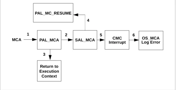
When the processor detects an error, control is transferred to the PAL_MCA entrypoint. PAL_MCA will perform error analysis and processor error correction where possible. Subsequently, PAL either returns to the interrupted context or hands off control to the SAL_MCA component. The level of recovery provided by PAL_MCA is implementation dependent and is beyond the scope of this specification. SAL_MCA will perform error logging and platform error correction where possible. Errors that are corrected by PAL and SAL firmware are logged and control is transferred back to the interrupted
process/context. For corrected errors, no OS intervention is required for error handling, but the OS is notified of the event for logging purposes through a low priority
asynchronous corrected machine check interrupt (CMCI). See Section 5.8.3.8, “Corrected Machine Check Vector (CMCV – CR74)” for more information on the CMCI. If the error was not corrected by firmware, SAL hands off control to the OS_MCA handler.
b. Added correctable machine check flow:
5.
Addition of
tf
instruction
1. Volume 3: Added tf I-page.
Figure 13-3. Correctable Machine Check Code Flow
PAL_MC_RESUME
PAL_MCA SAL_MCA OS_MCA
Log Error CMC Interrupt MCA 1 2 4 Return to Execution Context 3 5 6
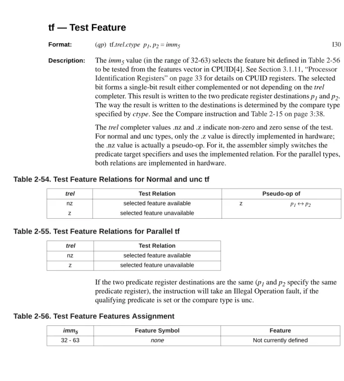
tf — Test Feature
Format: (qp) tf.trel.ctype p1, p2 = imm5 I30 Description: The imm5 value (in the range of 32-63) selects the feature bit defined in Table 2-56
to be tested from the features vector in CPUID[4]. See Section 3.1.11, “Processor Identification Registers” on page 33 for details on CPUID registers. The selected bit forms a single-bit result either complemented or not depending on the trel completer. This result is written to the two predicate register destinations p1 and p2. The way the result is written to the destinations is determined by the compare type specified by ctype. See the Compare instruction and Table 2-15 on page 3:38. The trel completer values .nz and .z indicate non-zero and zero sense of the test. For normal and unc types, only the .z value is directly implemented in hardware; the .nz value is actually a pseudo-op. For it, the assembler simply switches the predicate target specifiers and uses the implemented relation. For the parallel types, both relations are implemented in hardware.
If the two predicate register destinations are the same (p1 and p2 specify the same predicate register), the instruction will take an Illegal Operation fault, if the qualifying predicate is set or the compare type is unc.
Table 2-54. Test Feature Relations for Normal and unc tf
trel Test Relation Pseudo-op of
nz selected feature available z p1↔p2
z selected feature unavailable
Table 2-55. Test Feature Relations for Parallel tf
trel Test Relation nz selected feature available
z selected feature unavailable
Table 2-56. Test Feature Features Assignment
imm5 Feature Symbol Feature
Operation: if (PR[qp]) { if (p1 == p2)
illegal_operation_fault();
tmp_rel = cpuid[4]{imm5};
if (trel == ‘z’) // ‘z’ - test for 0, not 1 tmp_rel = !tmp_rel;
switch (ctype) {
case ‘and’: // and-type compare
if (!tmp_rel) { PR[p1] = 0;
PR[p2] = 0;
} break;
case ‘or’: // or-type compare
if (tmp_rel) { PR[p1] = 1;
PR[p2] = 1;
} break;
case ‘or.andcm’: // or.andcm-type compare if (tmp_rel) {
PR[p1] = 1;
PR[p2] = 0;
} break;
case ‘unc’: // unc-type compare
default: // normal compare
PR[p1] = tmp_rel; PR[p2] = !tmp_rel; break; } } else { if (ctype == ‘unc’) { if (p1 == p2) illegal_operation_fault(); PR[p1] = 0; PR[p2] = 0; } }
Interruptions: Illegal Operation fault
2. Update Table 4-4 on page 3:258 with the new format:
3. Updated Section 4.3.3 of Volume 3 on page 3:279:
4.3.3
Test Bit
All test bit instructions are encoded within major opcode 5 using a 2-bit opcode extension field in bits 35:34 (x2) plus five 1-bit opcode extension fields in bits 33 (ta), 36 (tb), 12 (c), 13 (y) and 19 (x). Table 4-23 summarizes these assignments.
Test NaT I17 5 tb x2 ta p2 r3 x y c p1 qp
4.3.3.1
Test Bit
I16
4.3.3.2
Test NaT
I1
Table 4-23. Test Bit Opcode Extensions
Opcode Bits 40:37 x2 Bits 35:34 ta Bit 33 tb Bit 36 c Bit 12 y Bit 13 x Bit 19 0 1 5 0 0 0 0 0 tbit.z I16 1 tnat.z I1 tf.z I30 1 0 tbit.z.unc I16
1 tnat.z.unc I1 tf.z.unc I30
1
0 0 tbit.z.and I16
1 tnat.z.and I1 tf.z.and I30
1 0 tbit.nz.and I16
1 tnat.nz.and I1 tf.nz.and I30
1 0
0 0 tbit.z.or I16
1 tnat.z.or I1 tf.z.or I30
1 0 tbit.nz.or I16
1 tnat.nz.or I1 tf.nz.or I30
1
0 0 tbit.z.or.andcm I16
1 tnat.z.or.andcm I1 tf.z.or.andcm I30
1 0 tbit.nz.or.andcm I16
1 tnat.nz.or.andcm I1 tf.nz.or.andcm I30
40 37 36 35 34 33 32 27 26 20 19 14 13 12 11 6 5 0
5 tb x2 ta p2 r3 pos6b y c p1 qp
4 1 2 1 6 7 6 1 1 6 6
Instruction Operands Opcode Extension
x2 ta tb y c tbit.z p1, p2 = r3, pos6 5 0 0 0 0 0 tbit.z.unc 1 tbit.z.and 1 0 tbit.nz.and 1 tbit.z.or 1 0 0 tbit.nz.or 1 tbit.z.or.andcm 1 0 tbit.nz.or.andcm 1 40 37 36 35 34 33 32 27 26 20 19 18 14 13 12 11 6 5 0 5 tb x2 ta p2 r3 x y c p1 qp 4 1 2 1 6 7 1 5 1 1 6 6
4. New Section 4.3.9, “Test Feature.”
4.3.9
Test Feature
I30
5. In Table 5-5, Volume 3, Section 5.4; add tf to “pr-gen-writers-int” and “pr-readers-nobr-nomovpr” entries.
6. Volume 3, Section 4.8; add new tf entry after I24 entry in Table 4-74, “Immediate Formation.”
7. Volume 3, Section 4.3.2, on page 3-283, update Tables 4-21 and 4-22 to reflect new tf
instruction.
a. In Table 4-21, change 5:0:0:1 entry from “Test NaT” to “Test Nat/Test Feature.” b. In Table 4-22, change 5:0:1:- entry from “Test Bit/Test NaT” to “Test Bit/Test Nat/Test
Feature.”
6.
Removal of requirement for externally connected pins
1. All references to INIT, PMI, and LINT pins restated to allow for their absence.
a. Volume 2, Part I, Section 5.8 “Interrupts” on page 2:97, first paragraph, change the following from:
Instruction Operands Opcode Extension
x2 ta tb y x c tnat.z p1, p2 = r3 5 0 0 0 1 0 0 tnat.z.unc 1 tnat.z.and 1 0 tnat.nz.and 1 tnat.z.or 1 0 0 tnat.nz.or 1 tnat.z.or.andcm 1 0 tnat.nz.or.andcm 1 40 37 36 35 34 33 32 27 26 20 19 18 14 13 12 11 6 5 0 5 tb x2 ta p2 0 x imm5b y c p1 qp 4 1 2 1 6 7 1 5 1 1 6 6
Instruction Operands Opcode Extension
x2 ta tb y x c tf.z p1, p2 = imm5 5 0 0 0 1 1 0 tf.z.unc 1 tf.z.and 1 0 tf.nz.and 1 tf.z.or 1 0 0 tf.nz.or 1 tf.z.or.andcm 1 0 tf.nz.or.andcm 1
“As shown in Figure 5-3, interrupts are managed by the processor and by one or more intelligent external interrupt controllers or devices in the I/O subsystem.”
to:
“Interrupts are managed by the processor and by one or more intelligent external interrupt controllers or devices in the I/O subsystem. Figure 5-3 shows just one example of a high performance interrupt architecture subsystem; other topologies are possible.” b. Volume 2, Part I, Section 5.8, add reference and footnote to LINT, INIT, PMI pins in the
locally connected devices bullet.
“Locally connected devices - These interrupts originate on the processor's interrupt pins (LINT, INIT, PMI)1, and are always directed to the local processor. “
In footnote:
“1. Processors are not required to support externally connected interrupt pins. Software can query the presence of the INIT, PMI, and LINT pins via the PAL_PROC_GET_FEATURES procedure call.”
c. Volume 2, Part I, Section 5.8.1 “Interrupt Vectors and Priorities”, change the second sentence in the second paragraph from:
“Assertion of the processor's PMI pin results in PMI vector number 0." to:
“Assertion of the processor's PMI pin, when present, results in PMI vector number 0." d. Volume 2, Part I, Section 5.8.3.9, modify references to LINT pins in the first paragraph
from:
“Local Redirection Registers (LRR0-1) steer external signal based interrupts that are directly connected to the local processor to a specific external interrupt vector. All processors support two direct external interrupt pins. These External interrupt signals (pins) are referred to as Local Interrupt 0 (LINT0) and Local Interrupt 1 (LINT1).” to:
“Local Redirection Registers (LRR0-1) steer external signal based interrupts that are directly connected to the local processor to a specific external interrupt vector. Processors may optionally support two direct external interrupt pins. When supported these external interrupt signals (pins) are referred to as Local Interrupt 0 (LINT0) and Local Interrupt 1 (LINT1). Software can query the presence of these pins via the PAL_PROC_GET_FEATURES procedure call.”
e. Volume 2, Part I, Section 5.8.4.2 “Interrupt and IPI Ordering”, change the first paragraph from:
“Interrupt messages from external device(s), or external interrupts routed to the processor's LINT pins, may arrive at one or more processors and become pending in any order. No ordering is enforced by the processor or the platform.”
to:
“Interrupt messages from external device(s), or external interrupts routed to the processor's LINT pins, when present, may arrive at one or more processors and become pending in any order. No ordering is enforced by the processor or the platform.” f. Volume 2, Part I, Section 5.8.5 “Edge- and Level-sensitive Interrupts”, modify the first
sentence from:
“The processor's LINT pins directly support edge and level sensitive interrupts, however all other interrupt sources are edge sensitive.”
to:
“The processor's LINT pins, when present, directly support edge and level sensitive interrupts, however all other interrupt sources are edge sensitive.”
g. Volume 2, Part I, Section 11.5.1 “PMI Overview”, Table 11-10 “PMI Events and Priorities.” Add a footnote reference to the PMI pin row:
PMI Events Priority
PMI pin (a) (vector 0) Low
a. PMI pin is not required to be present on all systems. Also modify this sentence in the fourth paragraph from:
“Vector 0 is used to indicate the PMI pin event.” to:
“A PMI pin event, when the PMI pin (1) is present, is indicated by vector 0." Add footnote:
“1. PMI pin is not required to be present. Software can query the presence of PMI pin via the PAL_PROC_GET_FEATURES procedure call.”
h. Volume 2, Part II, Section 10.2 “Configuration of External Interrupt Vectors”, add a footnote reference to the second bullet:
“From the processor's LINT0 or LINT1 pins(1) (typically connected to an Intel 8259A compatible interrupt controller), or”
Add footnote:
“1. Processors optionally support two external interrupt pins. Software can query for the presence of LINT pins via the PAL_PROC_GET_FEATURES procedure call.” i. Volume 2, Part II, Section 10.5.6 “Local Redirection Example”, add the following note at
the end of the section:
“The Local Redirection Registers (LRR0-1) serves to steer external signal based interrupts that are directly connected to the processor. LRR0 and LRR1 control the external interrupt signals (pins) referred to as Local Interrupt 0 (LINT0) and Local Interrupt 1 (LINT1) respectively. The example below shows how to mask interrupt delivery on LINT0.
movl r18=(1<<16) ;;
mov cr.lrr0=r18 ;;
srlz.d // srlz.d is required after LRR write to ensure write effect.
Note: LINT0 and LINT1 pins are not required to be supported. Writes to LRR0-1 control registers would have no effect, and reads from LRR0-1 control registers would return 0."
2. Effects of writes to and reads from control registers LRR 0, 1 defined in the absence of LINT pins:
a. Volume 2, Part 1, Section 5.8.3.9, change the second paragraph from:
“To ensure that subsequent interrupts from LINT0 and LINT1 reflect the new state of LRR prior to a given point in program execution, software must perform a data serialization operation after an LRR write and prior to that point.”
to:
“To ensure that subsequent interrupts from LINT0 and LINT1 reflect the new state of LRR prior to a given point in program execution, software must perform a data serialization operation after an LRR write and prior to that point. In the case when LINT0 and LINT1 pins are absent, writes to LRR would have no effect, and reads from LRR would return 0. Software can query the presence of the LINT pins via the PAL_PROC_GET_FEATURES procedure call.”
3. Detection of INIT, PMI, and LINT pins presence via the PAL_PROC_GET_FEATURES procedure.
a. Volume 2, Part 1, Chapter 11, Table 11-54, insert new row:
b. Update the last row to:
7.
Architecture extensions for processor Power/Performance states
1. New Section 11.6.1 in Volume 2, Part I
11.6.1
Power/Performance States (P-states)
This section describes the power/performance states (hence to be referred as P-states) supported by the Itanium architecture. P-states enable the caller to adjust the power/performance characteristics of the processor in response to changing workload requirements. This allows for implementation of a processor-level power management policy which is driven by system demand and response time
requirements.
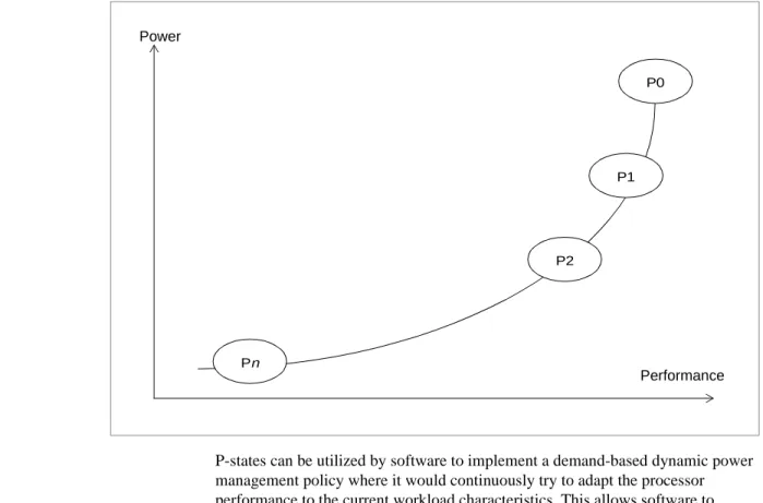
The P-states are defined within the context of the active/executing processor state. At the highest performing P-state (referred to as the P0 state), the processor uses its maximum performance capability and may consume maximum power. In the next P-state (P1), the processor performance capability is limited below the maximum performance, and it consumes less than the maximum power. Successive P-states continue to have reduced performance capabilities and reduced power consumption than the corresponding lower state. The Itanium architecture supports a maximum of 16 P-states, with the highest numbered P-state that is available on an
implementation providing the least possible performance capability and minimal power consumption while remaining in a non-HALT state.
Bit Class Control Description
37 Opt No INIT, PMI, and LINT pins present. Denotes the absence of INIT, PMI, LINT0, and LINT1 pins on the processor. When 1, the pins are absent. When 0, the pins are present. This feature may only be interrogated by PAL_PROC_GET_FEATURES. It may not be enabled or disabled by PAL_PROC_SET_FEATURES. The corresponding argument is ignored.
Bit Class Control Description
P-states can be utilized by software to implement a demand-based dynamic power management policy where it would continuously try to adapt the processor performance to the current workload characteristics. This allows software to achieve power savings at the system level, while allowing it to quickly respond to changing workload requirements.
The example in Figure 11-20 assumes four P-states (P0, P1, P2 and P3), and a software policy that transitions between the states depending on the current system utilization. During times of high utilization, the software migrates the processor towards lower-numbered P-states, which increases processor performance and increases the dissipated power. When system utilization is low, the software policy migrates the processor towards higher-numbered P-states, thereby reducing the processor performance and reducing dissipated power. The figure also shows the HALT state, which the software can transition to at any time from a given P-state.
Figure 11-19. Power and Performance Characteristics for P-states
P0 P1 P2 Pn Power Performance
The concept of P-states applies to each logical processor, and this gives software the required granularity to individually control the power/performance
characteristics for each available thread of execution in the system. In the most simplistic case, the processor package has only one thread of execution, and this allows software to apply the same P-state policy at the package-level as well as at the logical processor level. However, with implementations that support
multithreading and multiple cores, a single package can have multiple logical processors (threads of execution). These may have P-state dependencies among them, which may not allow for individual P-state control flexibility at the software level. For example, these logical processors may be sharing the same clock and power delivery network. In such circumstances, software would need to know which logical processors have dependencies and what the nature of the dependencies is, so that appropriate coordination techniques can be applied. To allow the architecture definition to comprehend for multi-threaded/multi-core designs, we define the concept of dependency domain and coordination mechanisms.
A dependency domain is comprised of logical processors that share a common set of implementation-dependant domain parameters that affect power consumption and performance for all logical processors in that domain. As an example, a processor package comprising of two cores controlled by the same clock and power distribution network are part of the same dependency domain, since changing either the operating frequency or voltage will affect power consumption and performance for both cores. Alternatively, if these two cores on the processor package had independent distribution networks for clocks and power, then a change in the parameters for one core would not have any effect on the other core, and in that case, the cores would not belong to the same dependency domain.
Figure 11-20. Example of a P-state Transition Policy
Halt P0 P1 P2 P3 Transitions initiated by software High Utilization Low Utilization
Software can utilize P-states to affect changes in the domain parameters. Each P-state maps to a set of values for the domain parameters, and hence a P-state transition results in a change in the underlying power/performance characteristics for the logical processor.
The Itanium architecture supports different types of dependency domains, which enables software to have different degrees of control for P-state changes affecting logical processors in the domain.
A software-coordinated dependency domain relies on the software to coordinate P-state changes among the processors in that dependency domain. Software will have knowledge about logical processors belonging to that domain, and will decide when it is appropriate to request the P-state transition. The software policy has to be aware that a P-state change on any logical processor will change the P-state for all logical processors in that domain. As an example, let us assume that the software-coordinated dependency domain consisted of two cores with the same clock and power distribution networks and the intent of the software policy was to lower power/performance only when the workload utilization was low on both cores. Software could then monitor utilization on both cores, and when both cores were under-utilized (i.e., were running at a higher performance P-state than required by the current system demand), it could migrate one of the cores to a lower performance P-state. This transition would simultaneously reduce
performance and power dissipation for both cores, and would result in both cores operating at the same P-state.
A hardware-coordinated dependency domain relies on hardware-based mechanisms to synchronize P-state changes. Software can make independent P-state change requests on individual processors, recognizing that hardware is responsible for the required coordination with other processors in the same hardware-coordinated dependency domain. Hardware-based coordination
mechanisms would be implemented to allow for changes to the logical processor's power and performance local parameters (which are implementation-dependant), in addition to the existing domain parameters. Hardware would use a combination of changes to both of these parameters to satisfy the software-initiated P-state change request. This type of coordination mechanism is effective when it is desired to have individual control over all logical processors, and when the hardware has local parameters for power/performance at the logical processor level. The local parameters allow for fine-grained control (affecting only the logical processor power/performance), whereas the domain parameters allow for coarse-grained control (affecting all logical processors). As an example, let us assume that the hardware-coordinated dependency domain consisted of two cores with the same clock and power distribution networks, and that there were also some other techniques to affect power and performance which were local to each logical processor. When software initiates a P-state transition on the first core, hardware would use only the local parameters to carry out the request. When software requests the same P-state change on the second core, then hardware can undo the changes to the local parameters for the first core, and then initiate changes to the domain parameters, which would allow both cores to operate at the same P-state. A hardware-independent dependency domain is a self-contained domain that typically means that every logical processor is the only logical processor in that domain, and its domain parameters are individually controllable. Since there are no
dependencies with any other logical processors, there is no P-state coordination needed for such domains. Software can make P-state change requests
independently on that logical processor.
The PAL procedure PAL_PROC_GET_FEATURES returns whether an
implementation supports P-states. If an implementation supports P-states then the PAL_PROC_SET_FEATURE procedure will allow the caller to enable or disable this feature.
The Itanium architecture provides three new PAL procedures to enable P-state functionality.
PAL_PSTATE_INFO: This procedure returns information about the P-states implemented on a particular processor. For details on the information returned by this procedure, please refer to the procedure description on page 2:361. The Itanium architecture supports a maximum of 16 P-states.
PAL_SET_PSTATE: This procedure allows the caller to request the transition of the processor to a new P-state. The procedure can either return with transition success (request was accepted) or transition failure (request was not accepted) depending on hardware capabilities, implementation-specific event conditions, and the spacing between successive PAL_SET_PSTATE procedure calls.
If hardware has the ability to either preempt a previous in-progress P-state transition, or to queue successive P-state requests while the first request is in transition, then the implementation has a preemptive policy for P-state request handling. The architecture also allows for a non-preemptive policy for P-state request handling, whereby a new PAL_SET_PSTATE request is not accepted if a previous P-state transition is already in progress. The PAL_SET_PSTATE procedure returns different status values corresponding to the accepted and not accepted cases for P-state requests. If the transition is not accepted, no P-state transition is initiated by the PAL_SET_PSTATE procedure, and the caller is expected to make another PAL_SET_PSTATE request to transition to the desired P-state. The transition_latency_2 field in the pstate_buffer returned by
PAL_PSTATE_INFO indicates the time interval the caller needs to wait to have a reasonable chance of success when initiating another PAL_SET_PSTATE call. If the logical processor belongs to a software-coordinated dependency domain, the PAL_SET_PSTATE procedure will change the domain parameters, which will result in all logical processors in that domain to transition to the requested P-state. If the logical processor belongs to a hardware-coordinated dependency domain, the PAL_SET_PSTATE procedure will attempt to change the power/performance characteristics only for that logical processor, which will result in either partial or complete transition to the requested P-state. In case of partial transition (see Figure 11-21, “Computation of performance_index” on page 2:310 for an example, where the logical processor transitions from state P0 to state P3 in partial
increments), the logical processor may attempt to perform changes at a later time to the local parameters and/or domain parameters to transition to the originally requested P-state. If the logical processor belongs to a hardware-independent dependency domain, the PAL_SET_PSTATE procedure will attempt to change the domain parameters, which will transition the logical processor in that domain to the requested P-state.
PAL_GET_PSTATE: This procedure returns the performance index of the logical processor, relative to the highest available P-state – P0 – which has an index value of 100. For example, if the value returned by the procedure is 80, it indicates that the performance of the logical processor over the last time period was 20% lower than the P0 performance capability of the logical processor. The performance index is measured over the time interval since the last PAL_GET_PSTATE call. Every invocation of the PAL_GET_PSTATE procedure resets the internal performance measurement logic, and initiates a new performance_index count, which is reported when the next PAL_GET_PSTATE procedure call is made.
If the logical processor belongs to a software-coordinated dependency domain or a hardware-independent dependency domain, the performance index returned corresponds to the target P-state requested by the most recent successful PAL_SET_PSTATE procedure call.
If the logical processor belongs to a hardware-coordinated dependency domain, the performance index returned will be a weighted-average sum of the perf_index values corresponding to the different P-states that the logical processor was operating in before the PAL_GET_PSTATE procedure was called. Note that this return value may not necessarily correspond to the performance index of the target P-state requested by the most recent PAL_SET_PSTATE procedure call. For example, let's assume that the previous PAL_GET_PSTATE procedure was called at time t0, when the processor was operating in state P0. The previous
PAL_SET_PSTATE procedure requested a transition from P0 to P3. The transition happened over a period of time, such that the logical processor went through states P1 at time t1, P2 at time t2 and P3 at time t3, and was in state P3 at time t4 when the current PAL_GET_PSTATE procedure was called. The performance_index returned is calculated as:
performance_index =
((time spent in P0 after the previous PAL_GET_PSTATE) * (performance_index for P0) +
(time spent in P1) * (performance_index for P1) + (time spent in P2) * (performance_index for P2) +
(time spent in P3 up to the current PAL_GET_PSTATE) * (performance_index for P3)) /
(time interval between previous and current PAL_GET_PSTATE) =
t
1–
t
0(
)
×
pf
0+
(
t
2–
t
1)
×
pf
1+
(
t
3–
t
2)
×
pf
2+
(
t
4–
t
3)
×
pf
3t
4–
t
0---As seen above, for a hardware-coordinated dependency domain, the
PAL_GET_PSTATE procedure allows the caller to get feedback on the dynamic performance of the processor over the last time period. The caller can use this information to get better system utilization over the next time period by changing the P-state in correlation with the current workload demand.
11.6.1.1
Interaction of P-states with HALT State
It is possible for a logical processor to enter and exit a HALT state between two consecutive calls to PAL_GET_PSTATE. Since the logical processor is not executing any instructions while in the HALT state, the performance index contribution during this period is essentially 0, and will not be accounted for in the
performance_index value returned when the next PAL_GET_PSTATE procedure
call is made.
For example, let us assume that the previous PAL_GET_PSTATE procedure was called at time t0, when the processor was operating in state P2. The previous PAL_SET_PSTATE procedure initiated a transition from P2 to P3 at time t1. The processor entered HALT state at time th1, and exited the HALT state at time th2, and was in state P3 at time t2 when the current PAL_GET_PSTATE procedure was called. The performance_index returned is calculated as:
performance_index =
((time in P2 after the previous PAL_GET_PSTATE) * (performance_index for P2) +
(time in P3 before entering HALT state) * (performance_index for P3) + (time in P3 after exiting HALT up to current PAL_GET_PSTATE))) * (performance_index for P3)) /
(time interval between previous and current GET, excluding time spent in HALT) =
Figure 11-21. Computation of performance_index
pf0 (P0) pf1 (P1) pf2 (P2) pf3 (P3) t0 t1 t2 t3 t4 Performance Time
As shown above, the value returned for performance_index does not account for the performance during the time spent by the logical processor in the HALT state. This provides for better accuracy in the value reported for performance_index, allowing the caller to make optimal adjustments to the system utilization even in scenarios where we have interactions between P-states and HALT state.
2. New Section 13.3.4 in Volume 2, Part II
13.3.4
P-state Feedback Mechanism Flow Diagram
The example flowchart shown below illustrates how the caller can utilize the PAL_SET_PSTATE and the PAL_GET_PSTATE procedures to manage system utilization and power consumption, for a processor implementation that belongs to either a hardware-coordinated dependency domain or a hardware-independent dependency domain. At the beginning of the loop, PAL_GET_PSTATE gives the performance characteristics of the processor over the last time period. It is assumed that the caller maintains an internal count for determining the busy ratio of the logical processor (busy ratio can be defined as the percentage of time the processor was busy executing instructions and not idle). The caller then seeks to adjust the P-state for the next time period to match the busy ratio from the previous time period. For example, if the busy ratio for a given period was 100%, and the
performance_index returned by PAL_GET_PSTATE was 60, then this indicates
that the P-state for the next time period should be P0 (which has performance index of 100). The caller would then call the PAL_SET_PSTATE procedure to transition the processor to the P0 state. In essence, if the busy ratio is greater than the
performance_index returned by PAL_GET_PSTATE, the caller responds to the
increased demand requirement of the workload by transitioning the processor to a higher-performance P-state. Alternatively, if the busy ratio is lower than the
t
1–
t
0(
)
×
pf
2+
(
t
h1–
t
1)
×
pf
3+
(
t
2–
t
h2)
×
pf
3t
2–
t
0(
)
–
(
t
h2–
t
h1)
---Figure 11-22. Interaction of P-states with HALT State
pf0 (P0) pf1 (P1) pf2 (P2) pf3 (P3) t0 t1 th1 th2 t2 Performance
(Previous) GET SET(P3) (Current) GET
Time Enter HALT State Exit HALT State
performance_index returned by PAL_GET_PSTATE, the caller responds by
transitioning the processor to a lower performance P-state, which consumes less power and operates at reduced performance.
Such an adaptive policy implemented by the caller to dynamically respond to system workload characteristics using P-states allows for efficient power utilization – the processor consumes additional power by operating at a higher performance level only when the current workload requires it to do so.
3. New PAL Power Management Procedures
Figure 13-6. Flowchart Showing P-state Feedback Policy
(1) getperfindex = PAL_GET_PSTATE (2) OS computes newpstate index from busy ratio and getperfindex
newpstate == getperfindex?
PAL_SET_PSTATE(newpstate)
Check Return Code
Mark newspstate as Invalid Current P-state = newpstate Reset busy ratio Yes No Status == -2 Status == 0
(Accepted) (Not Accepted)Status == 1 (Invalid)
Table 11-16. PAL Power Information and Management Procedures
Procedure Idx Class Conv. Mode Description
PAL_GET_PSTATE 262 Opt. Stacked Both Returns information on the performance index of the processor.
PAL_PSTATE_INFO 44 Opt. Static Both Returns information about the P-states supported by the processor.
PAL_SET_PSTATE 263 Opt. Stacked Both Request processor to enter power/performance state.
PAL_GET_PSTATE
Return Information on the Performance Index of the Processor
Purpose: Returns the performance index of the processor. Calling Conv: Stacked Registers
Mode: Physical and Virtual Arguments:
Returns:
Status:
Description: This procedure returns the performance index of the processor over the time period between the previous and the current invocations of PAL_GET_PSTATE, and is relative to the highest available P-state. For processors that belong to a
software-coordinated dependency domain or a hardware-independent dependency domain, the performance_index value returned will correspond to the target P-state requested by the most recent PAL_SET_PSTATE procedure call.
For processors that belong to a hardware-coordinated dependency domain, the type argument allows the caller to select the performance_index value that will be returned. See Table 11-48 below for details.
Argument Description
index Index of PAL_GET_PSTATE within the list of PAL procedures. type Type of performance_index value to be returned by this procedure. Reserved 0
Reserved 0
Return Value Description
status Return status of the PAL_GET_PSTATE procedure.
performance_index Unsigned integer denoting the processor performance for the time duration since the last PAL_GET_PSTATE procedure call was made. The value returned is between 0 and 100, and is relative to the performance index of the highest available P-state.
Reserved 0
Reserved 0
Status Value Description
1 Call completed without error, but accuracy of performance index has been impacted by a thermal throttling event, or a hardware-initiated event. 0 Call completed without error
-1 Unimplemented procedure -2 Invalid argument
For processors that belong to a software-coordinated dependency domain or a hardware-independent dependency domain, the PAL_GET_PSTATE procedure should always be called with type argument value of 0.
If there was a thermal-throttling event or any hardware-initiated event, which affected the processor power/performance for the current time period and the accuracy of the performance_index value has been impacted by the event, then the procedure will return with status=1. The performance_index returned in this case will still have a value between 0 and 100.
The procedure returns with a performance_index value of 100 when invoked for the first time. For subsequent invocations, the procedure will return the
performance_index value corresponding to the processor performance in the time
duration between the previous and current calls to PAL_GET_PSTATE. If the processor had transitioned to a HALT state (see Section 11.6.1, “Power/Performance States (P-states)” on page 2:305) in between successive invocations to the PAL_GET_PSTATE procedure, the performance index computation returned will not take into account the performance of the processor during the time spent in HALT state (see Section 11.6.1.1, “Interaction of P-states with HALT State” on page 2:310 for details).
Table 11-48. PAL_GET_PSTATE type Argument
type Description
0 The performance_index returned will correspond to the target P-state requested by the most recent PAL_SET_PSTATE procedure call.
1 The performance_index is a weighted-average value of the different P-states that the processor was operating in for the time duration between the current PAL_GET_PSTATE procedure call, and the previous invocation of PAL_GET_PSTATE with type=1. This allows the caller to establish a new starting point for subsequent computation of the
weighted-average performance_index. See Section 11.6.1, “Power/Performance States (P-states)” on page 19 for more details on how the weighted average value is derived. 2 The performance_index is a weighted-average value of the different P-states that the
processor was operating in for the time duration between the current PAL_GET_PSTATE procedure call, and the previous invocation of PAL_GET_PSTATE with type=1. This allows the caller to sample the current value of the performance_index, without affecting the starting point used for computing the weighted-average performance_index.
PAL_PSTATE_INFO
Get Information for Power/Performance States
Purpose: Returns information about the P-states supported by the processor. Calling Conv: Static Registers Only
Mode: Physical and Virtual Arguments:
Returns:
Status:
Description: Information about available P-states is returned in the data buffer referenced by
pstate_buffer. Entries in the buffer are organized in an ascending order. For
example, P0 (the highest performance P-state) state information is index 0 in the buffer, P1 state is index 1 in the buffer, and so on. The return argument pstate_num indicates the number of P-states supported on the given implementation. For example, if pstate_num is 4, it indicates that P-states P0-P3 are available for that implementation. Information in pstate_buffer is returned only for entries corresponding to the available P-states. Entries corresponding to unimplemented P-states must be ignored. Figure 11-49 illustrates the format of the pstate_buffer.
• typical_power_dissipation is a 20-bit field denoting the typical processor package power dissipation if all logical processors on the package are placed in this P-state, measured in milliwatts.
• perf_index is a 7-bit field denoting the performance index of this P-state, relative to the highest available P-state (P0). This field is enumerated on a scale of 0…100, with the value of 100 corresponding to the P0 state. For example, if Argument Description
index Index of PAL_PSTATE_INFO within the list of PAL procedures. pstate_buffer 64-bit pointer to a 256-byte buffer aligned on an 8-byte boundary. Reserved 0
Reserved 0
Return Value Description
status Return status of the PAL_PSTATE_INFO procedure.
pstate_num Unsigned integer denoting the number of P-states supported. The maximum value of this field is 16.
dd_info Dependency domain information Reserved 0
Status Value Description
0 Call completed without error -1 Unimplemented procedure
-2 Invalid argument, or P-states not supported on this implementation -3 Call completed with error
Figure 11-49. Layout of pstate_buffer Entry
offset 31 30 29 28 27 26 25 24 23 22 21 20 19 18 17 16 15 14 13 12 11 10 9 8 7 6 5 4 3 2 1 0
+0 typical_power_dissipation reserved perf_index
63 62 61 60 59 58 57 56 55 54 53 52 51 50 49 48 47 46 45 44 43 42 41 40 39 38 37 36 35 34 33 32 +4 transition_latency_1 31 30 29 28 27 26 25 24 23 22 21 20 19 18 17 16 15 14 13 12 11 10 9 8 7 6 5 4 3 2 1 0 +8 transition_latency_2 63 62 61 60 59 58 57 56 55 54 53 52 51 50 49 48 47 46 45 44 43 42 41 40 39 38 37 36 35 34 33 32 +12 reserved 64
the P1-state has a value of 75, and the next P-state (P2) has a value of 50, it implies that P1 performance is 25% lower than P0 performance, and P2 performance is 50% lower than P0 performance.
• transition_latency_1 is a 32-bit field indicating the minimum number of processor cycles required to initiate a transition to this P-state from any other P-state.
• transition_latency_2 is a 32-bit field indicating the minimum recommended number of processor cycles that the caller should wait, before initiating a new P-state transition with a reasonable chance of acceptance. This field is intended to give the caller an estimation of the frequency with which PAL_SET_PSTATE procedure calls should be made, without having the transition request be not accepted.
Dependency domain details for the logical processor are returned in dd_info. See Figure 11-50 for dd_info layout.
• ddt (Dependency Domain Type) is a 3-bit unsigned integer denoting the type of dependency domains that exist on the processor package. The possible values are shown in Table 11-65. See Section 11.6.1, “Power/Performance States (P-states)” on page 19 for details of the values in this field.
• ddid (Dependency Domain Identifier) is a 6-bit unsigned integer denoting this logical processor's dependency domain. The ddid values are unique only for a given processor package. Software can use the ddid field to determine which logical processors belong to the same dependency domain within the package. For more information on performance states and power management, refer to Section 11.6.1, “Power/Performance States (P-states)” on page 19.
Figure 11-50. Layout of dd_info Parameter
31 30 29 28 27 26 25 24 23 22 21 20 19 18 17 16 15 14 13 12 11 10 9 8 7 6 5 4 3 2 1 0
reserved ddit rv ddt
63 62 61 60 59 58 57 56 55 54 53 52 51 50 49 48 47 46 45 44 43 42 41 40 39 38 37 36 35 34 33 32
reserved
Table 11-65. Values for ddt Field
Value Description
0 Hardware independent 1 Hardware coordinated 2 Software coordinated 3-7 Reserved
PAL_SET_PSTATE
Request Processor to Enter Power/Performance State
Purpose: To request a processor transition to a given P-state. Calling Conv: Stacked Registers
Mode: Physical and Virtual Arguments:
Returns:
Status:
Description: PAL_SET_PSTATE is used to request the transition of the processor to the P-state specified by the p_state input parameter. The PAL_SET_PSTATE procedure does not wait for the transition to complete before returning back to the caller. The request may either be accepted (status = 0) or not accepted (status = 1), depending on hardware capabilities and implementation-specific event conditions. If the request is not accepted, then no transition is performed, and it is up to the caller to make another PAL_SET_PSTATE procedure call to transition to the desired P-state. When the request is accepted, it will attempt to initiate a transition to the requested performance state. For processors that belong to a software-coordinated dependency domain or a hardware-independent dependency domain, the procedure will always succeed in transitioning to the requested performance state. If the processor belongs to a hardware-coordinated dependency domain, the procedure will make a best-case attempt at fulfilling the transition request, based on the nature of the dependencies that exist between the logical processors in the domain. In such circumstances, the procedure may initiate no transition, partial transition or full transition to the requested P-state. Since there is the possibility that the procedure may initiate no processor transition, there are implementation-specific forward progress requirements.
The force_pstate argument may be used for a hardware-coordinated dependency domain when it is necessary to get a deterministic response for the P-state transition at the expense of compromising the power/performance of other logical processors in same domain. If the force_pstate argument is non-zero, and if the request is accepted, the procedure will initiate the P-state transition on the logical processor regardless of any dependencies that exist in the dependency domain at the time the procedure is called. The force_pstate argument is ignored for software-coordinated and hardware-independent dependency domain. Argument Description
index Index of PAL_SET_PSTATE within the list of PAL procedures. p_state Unsigned integer denoting the processor P-state being requested.
force_pstate Unsigned integer denoting whether the P-state change should be forced for the logical processor.
Reserved 0
Return Value Description
status Return status of the PAL_SET_PSTATEprocedure. Reserved 0
Reserved 0 Reserved 0
Status Value Description
1 Call completed without error, but transition request was not accepted 0 Call completed without error
-1 Unimplemented procedure -2 Invalid argument
4. Add a new row to Processor Features, Table 11-54 on page 2:360:
8.
Allow Undefined Behavior for All Must-be-last Instructions
1. Volume 1, Section 4.1.2, 4th paragraph, change from:
A cover instruction must be the last instruction in an instruction group otherwise an Illegal Operation fault is taken.
to:
A cover instruction must be the last instruction in an instruction group; otherwise, operation is undefined.
2. Volume 2, Section 6.5.4, 2nd paragraph, change from:
The cover instruction must be specified as the last instruction in a bundle group otherwise an Illegal Operation fault is taken.
to:
A cover instruction must be the last instruction in an instruction group; otherwise, operation is undefined.
3. Volume 3, bsw instruction page:
a. Description, 2nd paragraph, change from:
A bsw instruction must be the last instruction in an instruction group. Otherwise, an Illegal Operation fault is taken.
to:
A bsw instruction must be the last instruction in an instruction group; otherwise, operation is undefined.
b. Operation. Change from:
if (!followed_by_stop()) illegal_operation_fault();
to:
if (!followed_by_stop()) undefined_behavior();
c. Interruptions. Remove “Illegal Operation fault”. 4. Volume 3, clrrrb instruction page.
a. Description, 2nd paragraph, change from:
This instruction must be the last instruction in an instruction group, or an Illegal Operation fault is taken.
to:
This instruction must be the last instruction in an instruction group; otherwise, operation is undefined.
b. Operation. Change from:
if (!followed_by_stop()) illegal_operation_fault();
Table 11-54. Processor Features
Bit Class Control Description
52 Opt. Req. Disable P-states. When 1, the PAL P-state procedures (PAL_PSTATE_INFO, PAL_SET_PSTATE, PAL_GET_PSTATE) will return with a status of -1 (Unimplemented procedure).
to:
if (!followed_by_stop()) undefined_behavior();
c. Interruptions. Change “Illegal Operation fault” to “None”. 5. Volume 3, cover instruction page.
a. Description, 2nd paragraph, change from:
A cover instruction must be the last instruction in an instruction group. Otherwise, an Illegal Operation fault is taken.
to:
A cover instruction must be the last instruction in an instruction group; otherwise, operation is undefined.
b. Operation. Change from:
if (!followed_by_stop()) illegal_operation_fault();
to:
if (!followed_by_stop()) undefined_behavior();
c. Interruptions. Remove “Illegal Operation fault”. 6. Volume 3, rfi instruction page.
a. Description, 2nd paragraph, change from:
This instruction must be immediately followed by a stop. Otherwise, an Illegal Operation fault is taken.
to:
This instruction must be immediately followed by a stop; otherwise, operation is undefined.
b. Operation. Change from:
if (!followed_by_stop()) illegal_operation_fault();
to:
if (!followed_by_stop()) undefined_behavior();
c. Interruptions. Remove “Illegal Operation fault”.
9.
Addition of PAL_BRAND_INFO
1. Add a new row to Table 11-14, Volume 2, Part I: Procedure - PAL_BRAND_INFO
Idx - 274 Class - Opt. Conv. - Stacked Mode - Both
2. New PAL Procedure:
PAL_BRAND_INFO
Provides Processor Branding Information
Purpose: Provides processor branding information. Calling Conv: Stacked Registers
Mode: Physical and Virtual Arguments:
Returns:
Status:
Description: PAL_BRAND_INFO procedure calls are used to ascertain the processor branding information.
The info_request input argument for PAL_BRAND_INFO describes which processor branding information is being requested. The info_request values are split into two categories: architected and implementation-specific. The architected
info_request have values from 0-15. The implementation-specific info_request
have values 16 and above. The architected info_request are described in this document. The implementation-specific info_request are described in processor-specific documentation.
This call returns the processor brand information as requested with the info_request argument. Table 11-25 describes the values.
Argument Description
index Index of PAL_BRAND_INFO within the list of PAL procedures.
info_request Unsigned 64-bit integer specifying the information that is being requested. (See Table 11-25)
address Unsigned 64-bit integer specifying the address of the 128-byte block to which the processor brand string shall be written.
Reserved 0
Return Value Description
status Return status of the PAL_BRAND_INFO procedure.
brand_info Brand information returned. The format of this value is dependent on the input values passed.
Reserved 0 Reserved 0
Status Value Description
0 Call completed without error -1 Unimplemented procedure -2 Invalid argument
-3 Call completed with error
-6 Input argument is not implemented
Table 11-25. Processor Brand Information Requested
Value Description
0 The ASCII brand identification string will be copied to the address specified in the address input argument. The processor brand identification string is defined to be a maximum of 128 characters long; 127 bytes will contain characters and the 128th byte is defined to be NULL (0). A processor may return less than the 127 ASCII characters as long as the string is null terminated. The string length will be placed in the
brand_info return argument. All Other Values Reserved
This procedure will return an invalid argument if an unsupported info_request argument is passed as an input or a -6 if the requested information was not available on the current processor.