A Framework for Mobile Object Recognition of
Internet of Things Devices and Inference with
Contexts
Jinsuk Kang
Jangwee Research Institute for National Defence, Ajou Univerisity, suwon-city, South Korea Email: [email protected]
Abstract—
integrated camera, users can interact with objects or Things in a very simple manner. A further advantage is that the objects themselves don’t have to be tagged with any kind of markers. Also, Quantitative validation of experimental results, while presenting an accurate rate, an early detection rate and a correct duration rate with detecting the intent of several smart-phone performing various activities, shows that proposed research contributes to implement effective intent recognition system.
Index Terms—Internet of Things, Smart-phone, LBS,
Speeded up Robust, Object Recognition.
I. INTRODUCTION
The emergence of new types of portable computing devices and developments in wireless networking are broadening the domain of computing from the work place and home office to other facets of everyday life. This trend is expected to lead to a proliferation of Internet of Things (IoT) environments, in which inexpensive and interconnected computing devices are capable of supporting users in a range of tasks. Context-aware computing is a key source to develop such smart services [1], [2]. Also, Understanding agent's intent is an essential component of the human-computer interaction of Smart- phone. Because correct inference of subjects intention in portable computing system helps particularly to understand situations that involve collaboration among multiple agents or detection of situations that can pose a particular activity [3].
Among the features, context-sensing capability is taken as a vehicle in deriving a new form of computation and applications, called context-aware IoT computing. With the advent of diverse context sensors of IoT devices, applications functionality is delivered for the analyzed contexts. The usefulness of context-aware IoT computing is already known, such as location based service (LBS). A key benefit of context-aware mobile computing is the capability of tailoring and delivering various services for the inferred contexts; hence, mobile users can experience personalized and context-adapted services [4].
In this paper, The results from Smart-phones are from simple digit number to images. Depending on types of
Manuscript received July 20, 2013; revised September 21, 2013
these results, it requires different types of reasoning algorithms. This paper provides structural and behavioral model of reasoning engine, which can employ one or more reasoning algorithms. This scheme enables to improve correctness of reasoning results. Also, we present a method and system enabling the Internet of Things using object recognition for certain types of objects or things. At the core of our server-side system lies a retrieval engine which indexes objects using scale invariant visual features. Users can take a picture of an object of interest, which is sent to the retrieval engine. The corresponding object is recognized and an associated action is executed, e.g. a web-site about the object is opened.
II. RELATED WORKS OF FACTOR
A. Semantic Technologies & Internet of Things
Internet and Things (IoT) requires devices and applications that can easily connect and exchange information in an ad-hoc fashion with other systems. This will require devices and services to express needs and capabilities in formalized ways. To facilitate the interoperability in the IoT further research into semantic technologies is needed. Examples of challenges are large-scale distributed ontologies, new approaches to semantic web services, rule engines and approaches for hybrid reasoning over large heterogeneous data and fact bases, semantic-based discovery of devices and semantically driven code generation for device interfaces.
B. Resource-constrained Scenarios for Business based IoT
IoT implies that even the smallest device or sensor could be connected to the network. Research in wireless sensor networks has already resulted in promising solutions, tools and operating systems that can run on very small and resource-constrained devices. These solutions need to be evaluated in real large-scale industrial applications in order to illustrate business-based scenarios for IoT.
C. Modeling and Design
The design of large-scale IoT systems is challenging due to the large number of heterogeneous components involved and due to the complex iterations among
devices introduced by cooperative and distributed approaches. To cope with this issue, innovative models and design frameworks need to be devised; for example, inspired by co-simulation methods for large systems of systems and hardware in the loop approaches.
D. Barcode Scanning on Smart-phone
With the rise of the mobile phone platform released by Google, the share of smart-phones has been constantly growing [5]. A key advantage of smart-phones is the ability to access the internet while on the go [6]. Interaction wise however, smart-phones still fight a number of teething problems, including the cumbersome entry of data. 1D or linear barcodes are the black and white striped codes that can be found on most consumer products. A recent approach to facilitate the interaction between mobile phones and products is the scanning of glued on tags. Examples are the scanning of square shaped two-dimensional barcodes and the scanning of RFID tags. Yet, almost all consumer products are equipped with the black-and-white striped 1D or linear barcodes1, which makes scanning of these tags using mobile phones the most applicable modality [7]. Scanning 1D barcodes using mobile phones works in a way that a piece of software installed on a mobile phone accesses the phone’s camera and, based on an image taken, calculates the code and outputs the number recognized.
III. T CHOSEN ARCHITECTURE
A. Theoretical Comparison and Methodology
Estimation of the 3-D position and orientation of a camera from its 2-D images is one of the most fundamental problems in computer vision. This problem, which is called camera localization, also needs to be solved for autonomous mobile robot guidance. After the software decides that a captured image of a scene comprises a natural landmark (object, building, road etc.), the next problem is estimating the relative position of the camera with respect to the object. It is assumed that the width of the object is known a priori, and the lower corner points of the object, which serve as feature points, are visible in the digitized image.
Figure. 1. Camera and world coordinate systems
In this paper, the range estimation process utilizes the simple perspective projection equations adapted by Haralick for position estimation of a rectangle. Throughout the position estimation process, the only features used that are related to the object (book) are the
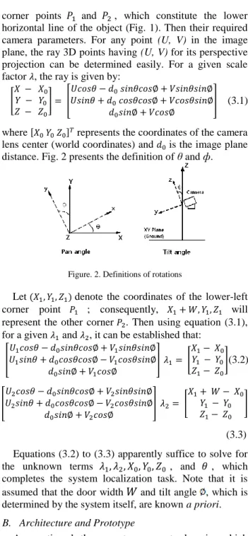
corner points and , which constitute the lower horizontal line of the object (Fig. 1). Then their required camera parameters. For any point (U, V) in the image plane, the ray 3D points having (U, V) for its perspective projection can be determined easily. For a given scale factor , the ray is given by:
[ ] [ ] (3.1)
where [ ] represents the coordinates of the camera lens center (world coordinates) and is the image plane distance. Fig. 2 presents the definition of θ and ф.
Figure. 2. Definitions of rotations
Let denote the coordinates of the lower-left corner point ; consequently, will represent the other corner . Then using equation (3.1), for a given and , it can be established that:
[ ] [ ](3.2) [ ] [ ] (3.3) Equations (3.2) to (3.3) apparently suffice to solve for the unknown terms , and , which completes the system localization task. Note that it is assumed that the door width and tilt angle , which is determined by the system itself, are known a priori.
B. Architecture and Prototype
As mentioned, there are two separate domains which we want to combine in our approach: The internet of Things and Physical interactions where mobile devices are used to interact with physical objects. The main goal of our approach is to connect these two domains whereas the mobile device acts as a mediator between them. Figure 3 depicts a high level view of our architecture. The mobile device acts as a Universal Client which is independent from the physical objects it interacts with and also from services it invokes. To interact with both domains it uses different components denoted as Interaction Client and Service Client.
The Interaction Client detects unique identifiers and additional data stored on the Physical Object while the Service Client communicates with the service domain. The Universal Client stores user context information and device capabilities which could enrich the automatic user HE
interface generation. As device context we consider several mobile platforms which vary in their physical interaction capabilities (e.g. smart-phone camera) and user interface capabilities (e.g. XHTML browser or J2ME runtime environment). Therefore, the Universal Client has to be able to support an arbitrary combination of device capabilities involved in the interaction process.
C. Model Description and Matching
The resulting model is a very compact description of the appearance of the model photo. Many of these models, based on the same visual word vocabulary, can be saved in a compact database. In our beverage carton sorting application, we build a database of all different carton prints to be recognized.
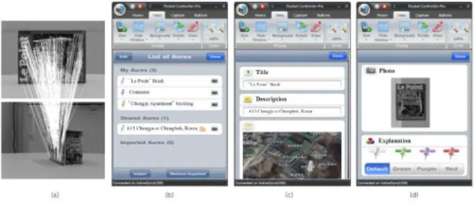
Once a database of objects to be recognised is built, these objects can be detected in a query image. The object detection algorithm here described gives cues where beverage cartons are located. With this information, a mechanical device can sort out the beverage cartons. After SURF local feature extraction, matching is performed with the visual words in the vocabulary. We used Mount’s ANN [10] algorithm for this. As seen in Figure 4, some of the visual words of the object are recognised, amidst other visual words.
1) Anchor location voting. Because each SURF feature
has a certain scale and rotation, we can reconstruct the anchor pixel location by using the feature-relative polar coordinates of the object anchor. For each instance in the object model description, this yields a vote for a certain anchor location. In Figure 5, this is depicted by the black lines ending with a black dot at the computed anchor location. Ideally, all these locations would coincide at the correct object centre. Unfortunately, this is not the case due to mismatches and noise. Moreover, if there are two identical visual words in the model description of an object, each detected visual word of that kind in the query image will cast to different anchor location votes, of which only one can be correct.
2) Object Detection. For all different models in the
database, anchor location votes can be quickly computed. Next task is to decide where a certain object is detected. Because a certain object can be present more than once in the query image, it is clear that a simple average of the anchor position votes is not a sufficient technique, even if robust estimators like RANSAC (Random Sample Consensus) are used to eliminate outliers. Therefore, we construct a Hough space, a matrix which is initiated at zero and incremented at each anchor location vote, Figure 4. The local maxima of the resulting Hough matrix are computed and interpreted as detected object positions.
D. Mobile Image Recognition System
The recognition approach consists of two steps: feature matching and global geometric verification. For the feature matching we compare the feature vectors from the query image to those of the images in the database. More precisely, for each 64-dimensional query vector, we calculate the Euclidean distance to the database vectors. A match is declared if the distance to the nearest neighbor
is smaller than 0.7 times the distance to the second nearest neighbor.
Finding the best result could now be done by just selecting the query-database pair, which receives the highest number of matches. However, without verification of the geometric arrangement of the matched interest points, the wrong query-database pair may be selected. This is particularly true in our case, where we have a high number of matches stemming from letters in text parts of the objects. These matches are all “correct” on the feature level, but only their consistent arrangement to full letters and words is correct on the semantic level. To solve this problem, we resort to projective geometry. Since the objects in the database are planar, we can rely on a 2D homography mapping from the query image to a selected candidate from the database in order to verify the suggested matching. That is, the set of point correspondences between the matched interest points from query image
Hx
iq and database imagex
id must fulfill, 4 1 x i Hx id q i (3.4) Base Service 1 ……… Base Service n Context Service 1 ……… Context Service m Web service Domain Domain gap Physical mobile Interaction domain Detection Physical object Interaction Proxy Service Composition Reasoning UI Generation Client (Smart-phone, PDA, etc) - User/Device Context - Interaction Client - Service Client Corresponds to serviceFigure. 3. High level architecture for physical mobile interactions with the Internet of Things
Figure. 4. Smart-phone camera calibration using homography and matches for a query image with the correct database image.
where H is the 3×3 homography matrix whose 8 degrees of freedom can be solved with four point correspondences i14 . To be robust against the before-mentioned outliers we estimate H using RANSAC [10]. The quality of several estimated models is measured by the number of inliers, where an inlier is defined by a threshold on the residual error. The residual error for the model are determined by the distance of the true points from the points generated by the estimated H. The result of such a geometric verification with a homography is shown in Fig. 4.
IV. SMART-PHONE BASED INFER SITUATION AND IMPLEMENTATION
A. System Concept
We have developed several recognition algorithms that allow for the creation of links from nearly arbitrary parts of papers [8], [9]. Both text patches and blocks of image data can be associated with individualized information. Furthermore, the recognition algorithms reliably recognize the low quality images produced by most mobile cameras. The user only needs a thing, a camera phone, and a network connection. An alternative solution would use 2D bar codes such as QR codes. However, QR codes take up valuable space on a scene, are impossible to change after scene is show, and disrupt its appearance. Moreover, visual search can index arbitrary locations within a passage of object. Many QR-Codes could be needed to provide the same capabilities, which is unrealistic. Until now, the only system architecture that is practical is shown in Fig. 5. Individual frames are transmitted to a server where they are recognized the results returned to the smart-phone.
Background
“Detection” Things Image Smart-phone device with Camera Recognition algorithm and Database Server
Decision and Object : URL, multimedia Smart-phone camera Image
Figure. 5. Client and server architecture for mobile recognition
This client-server architecture poses a serious problem to end users. The time required to transmit a single image, recognize it and return the result to the phone can be long enough that a user may give up on the application.
Background
“Detection” Things Image
Smart-phone device with Camera Recognition algorithm and
database Database generator for recognizer and objects Real-time updates
Figure. 6. Client only architecture for Smart-phone camera image recognition
This system describes our experience with the architecture shown in Fig. 6 in which the database is on the phone and the recognition algorithm executes completely on the smart-phone. Our client runs with the camera in video mode in which 5 to 10 frames are acquired per second. The user can move the phone smoothly over a document as video frames are captured and recognized.
B. Experimental Result and Evaluation
The Client used a PDA (HP iPAQ 5550) with built-in 802.11 networking, an attached mobile camera (HP Photosmart Mobile Camera) with 320x240 resolution and an expansion-pack with a 4.66 GB PC card hard-drive to
store the application content. The resulting tourist system (iPAQ and accessories) weighs approx. 400g with a battery life of approx. 2 hours under field trail conditions. We anticipate that the application could be ported to a camera phone with little difficulty. In order to assess the feasibility of automated line extraction with 3D positioning and consequently its real-time realization, a rich set of potential image processing functions was developed in a Visual Embedded C 4.0 programming environment.
Figure 7. Mobile images in the recognition set: Experiment using the mobile device of a Target Object, and Screen shots of Cadastral
Information Service
If image measurements from GPS/INS are to be used, the result of exterior orientation must be actually applied in mapping and editing operations while photographing. It should be noted that the verification process of aerial mapping result is the most crucial process at the GPS/INS based digital photogrammetry. To this end, this study has compared the mapping result by the ways of AT results, plotter, and orientation, which is from basis of the Analytical raw map produced by the existing AT result.
If we examine Table I, the difference of about 76cm has been created with analytical & digital plotter by conventional AT for the horizontal error and error of 66cm in analytical plotter and 89cm in digital plotter have been created when AT results (conventional AT vs GPS/INS AT) have been set as the standard. Because the tolerable horizontal error while producing a 1/5,000 map by current public measurement operation standard is 3.5m (within 7mm according to map distance), it adequately satisfies the accuracy requirements without any problems in practical usage. In vertical error, the difference of about 45cm has been created with analytical & digital plotter (using conventional AT) and error of 28cm in analytical plotter and 33cm in digital plotter have been created when AT results (conventional AT vs GPS/INS AT) have been set as the standard. And when descriptive horizontal and vertical error by analytical plotter and digital plotter are compared regardless of AT results and locating methods, The analytical plotter is showing better results than digital plotter.
TABLE 1:COMPARISON TABLE OF 1/5,000MAPPING RESULTS
Digital Plotter Tradition AT GPS/INS AT
Analytical Plotter Digital Plotter Analytical Plotter Digital Plotter Horizontal error Ref. Data 0.76 0.66 0.89 Vertical error Ref. Data 0.45 0.28 0.33
Also, as we can find out in Table I, we can see that the horizontal error is shown as greater than vertical error. The reason is estimated as descriptive error being included to some extent because the horizontal position of check point at 1/20,000 aerial photograph is relatively more difficult to make out than the vertical point installed on the ground.
Figure. 8. Recognition rate (left) and matching time (right) depending on radius around query location
Overall the best results are achieved with GPS and a rather large radius of several hundred meters. In Figure 8, we plot the precision versus time for different radius. At 100 meters we retrieve most of the objects correctly, but only between 300 and 500 meters we achieve the same recognition rates as for linear search, however at significantly higher speed. In fact, this speed-up over linear search will obviously be even larger, the more items are in the database. The recognition times can be further sped up with a suitable indexing structure such as [8], [9]. We have compared several methods, however the results are preliminary and beyond the scope of this paper.
V. CONCLUSION
We argue that the most desirable architecture for mobile image recognition runs the complete algorithm on the mobile device. Alternative solutions that run the recognizer on a remote server will not be as desirable because of the delay between image capture and receipt of a result that can cause users to abandon the technique. We presented an architecture for mobile object recognition that runs the complete algorithm on the device and thereby solves the problem that potentially dooms present day alternatives: the latency between image capture and recognition. Our technique for near real-time interaction between thing and camera phones allows users to retrieve electronic information linked to nearly arbitrary regions on a scene. The results showed, that the Internet of Things by object recognition can be realized already today. In fact, the system can be seen as a visual search engine for the Internet of Things. Relying just on an image sent from a Smart-phone, the system can be easily adopted by both end-users and system providers. With the advance of computer vision methods, we expect a wealth of additional possibilities in the coming years.
ACKNOWLEDGMENT
This research was supported by the MKE, Korea, under the ITRC support program supervised by the NIPA (NIPA-2013-(H0301-13-2003)), and also supported by Basic Science Research Program throuth the NRF funded by MEST (No.2010-0020985), and (No.2011-0015329).
REFERENCES
[1] Y. Lee, S. Iyengar, C. Min, Y. Ju, S. Kang, et al., “MobiCon: A mobile context-monitoring platform,” Communications of the ACM, vol. 55, no. 3, pp. 54-65, 2012.
[2] A. Padovitz, S. W. Loke, and A. Zaslavsky, “Multiple-agent perspectives in reasoning about situations for context-aware pervasive computing systems,” IEEE Transactions on Systems, Man, and Cybernetics, Part A: Systems and Humans, vol. 38, no. 4, pp.729-742, 2008.
[3] G. Kortuem, F. Kawsar, V. Sundramoorthy, and D. Fitton, “Smart objects as building blocks for the internet of things,” in Proc. IEEE Internet Computing, 2010, pp.30-37.
[4] M. Knappmeyer, N. Baker, S. Liaquat, and R. Tonjes, “Context provisioning framework to support pervasive and ubiquitous applications,” in Proc. 4th European Conference on Smart Sensing
and Context, 2009, pp. 93-106.
[5] R. Want, “When cell phones become computers,” IEEE Pervasive Computing, vol. 8, no. 2, pp. 2-5, 2009.
[6] R. Ballagas, J. Borchers, M. Rohs, and J. Sheridan, “The smart phone: A ubiquitous input device,” IEEE Pervasive Computing, vol. 5, no. 1, pp. 70-77, 2006.
[7] F. von Reischach, F. Michahelles, D. Guinard, et al., “An evaluation of product identification techniques for mobile phones,” in Proc. 12th IFIP TC13 Conference in Human-Computer Interaction, 2009, pp.804–816.
[8] J. Kang and R. Byeong-Hee, “Hierarchical graphical model-based object identification and categorization for smartphone,” Information-An International Interdisciplinary Journal, vol. 14, no. 6, pp. 2071-2086, 2011.
[9] J. Kang and R. Byeong-Hee, “Geo-cloud space of 3D perception for stereoscopic camera navigation and localization,” Information-An International Interdisciplinary Journal, vol. 14, no. 10, pp. 3395-3407, 2011.
[10] M. A. Fischer and R. C. Bolles, “Random sample consensus: A paradigm for model fitting with applications to image analysis and automated cartography,” Communications of the ACM, vol. 24, no. 6, pp. 381-395, 1981.
Jinsuk Kang received his B.S. degree in Information engineering from Cheju National University, Jeju, Korea, in 1999 and his M.S. and Ph.D. degrees in computer engineering from Cheju National University, Jeju, Korea, in 2001 and 2005, respectively. From 2006 to 2009, he was with the university of incheon, Korea, as a research professor. From February 2009 to March 2010, he worked with Chungbuk National University, Korea, as a visiting professor. Since March 2010, he has been with the Jangwee Research Institute for National Defence, Ajou University, Suwon, Korea, where he is currently a Research professor. His research interests include the areas of Multimedia, Computer Vision, Human-Computer Interaction, Mobile Computing and Embedded System, etc.