Operation Modes of Hot-Cathode Plasma Source for Linear
Devices
∗
)
Timur D. AKHMETOV
1,2), Vladimir I. DAVYDENKO
1,2), Alexandr A. IVANOV
1,2)and
Grigory I. SHULZHENKO
1)1)Budker Institute of Nuclear Physics, 11 Lavrentieva prospect, Novosibirsk 630090, Russia 2)Novosibirsk State University, 2 Pirogova str., Novosibirsk 630090, Russia
(Received 27 September 2018/Accepted 15 November 2018)
Operation of a plasma source with a hot disk cathode and a cylindrical hollow anode in axial magnetic field is sensitive to the cathode-to-anode diameter ratio. When the cathode edge maps along magnetic field lines to the inner anode surface, the discharge voltage is relatively low, and the plasma stream with moderate density occupies the entire cross-section of the anode bore. By contrast, when the cathode projection is fully inside the anode bore with the radial cathode-to-anode gap ∼ 1 cm, the discharge voltage jumps to much higher values exceeding 250 V. The plasma density profile becomes Gaussian-like with the width matching the cathode radius according to magnetic flux surfaces. The plasma density in the high-voltage cross-field discharge reaches 1013cm−3, and
the discharge parameters almost do not change with magnetic field up to 1.5 kG in the anode area. This plasma source is suitable for the use in linear devices for plasma-material interaction studies.
c
2019 The Japan Society of Plasma Science and Nuclear Fusion Research
Keywords: linear plasma device, lanthanum hexaboride cathode, hollow anode, cross-field discharge DOI: 10.1585/pfr.14.2406004
1. Introduction
Plasma-material interaction studies usually require a steady-state uniform dense plasma flow at a sample of sev-eral centimeters in size in a magnetic field of sevsev-eral kilo-gauss [1, 2]. Such plasmas can be produced using large-area LaB6 (lanthanum hexaboride) hot cathodes. For
ex-ample, the PISCES plasma generator with a LaB6 disk
cathode demonstrated good performance and capability of continuous operation [1]. An alternative configuration is used at the linear plasma device PSI-2, where the steady-state plasma is produced by an arc discharge between a cylindrical LaB6 hollow cathode and a hollow anode [2].
The narrow front surface of this cathode is mapped to the inner surface of the anode along the magnetic field lines, and the plasma density is strongly peaked off-axis.
This work continues our studies on plasma production using discharges with flat hot LaB6 cathodes [3, 4].
Pre-viously a plasma source with a segmented cathode and a hollow anode was studied, where the discharge regime was tuned using a separate control magnetic coil [3]. Another source design had a single-piece disk cathode and a 20 cm long anode with the bore profile reproducing the shape of the anode of the PSI-2 device [4], with the minimum diam-eter of 30 mm. However, in the latter discharge geometry the maximum gap across the magnetic field between the cathode edge and the inner surface of the anode was 5 mm, which most likely was insufficient for reliable operation author’s e-mail: [email protected]
∗)This article is based on the presentation at the 12th International Con-ference on Open Magnetic Systems for Plasma Confinement (OS2018).
of the cross-field discharge, because the discharge voltage did not exceed a moderate value of 180 V, and spontaneous transitions from the high-voltage to the low-voltage dis-charge were observed during the arc pulse.
In the present design the anode has a larger bore di-ameter of 70 mm, and a large range of magnetic field val-ues around the anode is available. Two operation modes studied here are different in terms of electrical contact be-tween the discharge electrodes in magnetic field. In the first mode later calleddirect discharge, the magnetic field geometry allows the field lines from the outer region of the cathode to intersect the anode surface. The second dis-tinct operation mode calledcross-field discharge, is char-acterized by a finite cathode-to-anode gap across the mag-netic field. In the majority of the experiments this gap was made equal to 1 cm which provided greater degree of magnetic insulation than in the previous experiments [4]. Two operation modes are characterized by different dis-charge voltages and plasma density radial distributions. In the cross-field mode the discharge voltage is significantly higher than in the direct discharge mode, and this voltage increases with the magnetic field value. The radial dis-tributions of the plasma density are also different in these two modes. The direct discharge mode produces relatively broad and flat-top plasma stream with moderate plasma density, whereas in the cross-field mode the plasma den-sity profiles are almost Gaussian and the peak denden-sity at the axis is≈ 1013cm−3. Thus, by switching the external
magnetic field coil around the anode, the plasma source
c
2019 The Japan Society of Plasma
can be operated in two different modes that can be useful for linear devices for plasma-material interaction studies.
2. Experimental Setup
The plasma is produced in a discharge with a hot flat cathode and a cylindrical anode in the axial magnetic field. A LaB6 disk with the open emitting surface of 46 mm in
diameter (16.6 cm2area) is heated by radiation from a flat spiral cut from a flexible graphite sheet (see the spiral in Fig. 7). The cathode together with the heater is surrounded by heat shields made of multilayer tantalum and graphite foils. The heater power sufficient for drawing the discharge current of 100 A (which corresponds to the average current density over the cathode surface of∼6 A/cm2) is≈1 kW.
The 80 mm long copper anode has the bore of 70 mm in diameter. The produced plasma stream flows through the anode along magnetic field to a 0.17 m3vacuum chamber
evacuated by a turbomolecular pump to a base pressure less than 1·10−5Torr. In our experiments the chamber is
grounded, the anode and the cathode are isolated from it, so the anode potential relative to the ground is not set ex-ternally. The working gas (hydrogen) is injected through the cathode flange, flows around the cathode and passes through the anode bore to the chamber. The discharge and plasma parameters remained almost the same as the gas flowrate was varied in the range 20 - 200 sccm, and in all subsequent experiments the flowrate was kept at 70 sccm to make correct comparison of the discharge modes. The plasma density and the electron temperature were mea-sured by a radially movable Langmuir probe atz=52 cm.
This linear plasma device does not have the cooling and pumping capabilities required for steady-state opera-tion, therefore it is operated in a pulse mode. The pulse length must be sufficient for achievement of the quasi steady-state discharge conditions, and at the same time the neutral gas distribution in the source must be determined by the stationary gas flow without a considerable pressure rise in the vacuum chamber. Thus discharges from 0.04 to 1.0 s were used. The maximum neutral pressure after a 1.2 s gas pulse for a 1.0 s long discharge in the vacuum chamber is6 mTorr (measured with the pumping cut off by a gate valve). The magnetic field coils produce the ax-ial magnetic field up to 1.5 kG in the plasma source region, and the field geometry is varied by changing the currents in separate coils. As described in the Introduction, the plasma source can be operated in two distinctly different modes determined by magnetic field geometry in the discharge region.
3. Results
3.1
Direct discharge
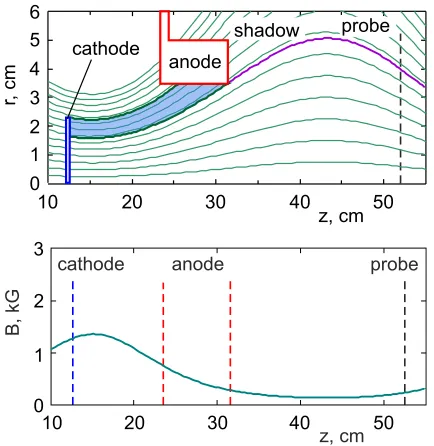
The direct discharge geometry with the magnetic field lines and the axial distribution of the magnetic field are shown in Fig. 1. The magnetic field in the anode region is made weak enough, so that the field lines from the cathode
Fig. 1 Direct discharge geometry and magnetic field on axis. Region of direct contact between cathode and anode along magnetic field is shaded.
Fig. 2 Radial profiles of probe ion saturation current in direct discharge mode at low and high magnetic field. Profile in cross-field mode is shown for comparison.
radius 1.6 to 2.3 cm intersect the anode surface forming the zone of direct electrical contact between the cathode and the anode along the field lines. For typical experi-mental settings listed above, the discharge voltage is about 120 V and the current can be easily increased to 100 A and more. The remaining inner area of the cathode occurs in the cross-field mode, but the discharge voltage is relatively low, because of high electron conductivity along the mag-netic field in the direct discharge zone. At low magmag-netic field in the whole plasma source (80 G in the anode) the electron temperature is 4.5±0.5 eV at the axis, 4.5 eV at
r=20 mm, and 4.0 eV atr=35 mm. The probe ion sat-uration currentIsat∝ne
√
Te, whereneis the electron
den-sity, and sinceTevariation over radius is small, the profile
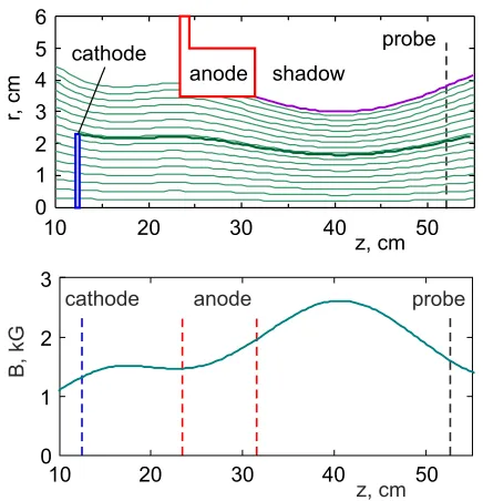
Fig. 3 Cross-field discharge geometry and magnetic field on axis.
ion saturation current at two magnetic field values with the same field distribution (discharge voltage 130 V, cur-rent 120 A). This discharge is weakly affected by magnetic field, at larger field the central density is smaller. The max-imum plasma density of 3.5·1012cm−3 at this discharge
power of 15 kW is achieved at low magnetic fields. In the circler 2 cm the plasma density decreases by less than 20%. Note the qualitative difference of these profiles from the one measured in the cross-field discharge and shown in Fig. 2 for comparison. The direct discharge mode is suitable for applications where a broad plasma stream with moderate density is required.
3.2
Cross-field discharge
The cross-field discharge geometry is shown in Fig. 3. The field line from the cathode edge passes at a distance of 1.3 cm from the anode forming a radial gap where elec-trons move to the anode across magnetic field. A geometric shadow to the right from the anode implies that the plasma density should be small at the probe position atr>4 cm, unless there is strong cross-field plasma transport. The magnetic field is almost uniform in the source and can be changed up to 1.5 kG as shown in the lower plot.
The discharge current is negligible until the voltage between electrodes reaches a threshold when the current abruptly jumps to several amperes. This breakdown volt-age grows almost linearly with the magnetic field as shown in Fig. 4, which reminds the linear dependence V(B) =
V0+v∗d ·B/c found experimentally in many cross-field
discharges where a plasma and a neutral gas are in rela-tive motion across a magnetic field; hereV0 is a sum of
potential drops at electrode sheaths,v∗is the constant with dimension of velocity,dis the distance between electrodes,
Fig. 4 Breakdown voltage in cross-field mode versus magnetic field: measured data and least squares linear regression.
Fig. 5 Probe current on axis versus arc power in cross-field dis-charge. Straight dashed line approximates data well for power less than 10 kW.
andcis the velocity of light [5, 6]. In the present experi-ment the relative motion of the plasma relative to the neu-tral gas is produced byE×Bazimuthal plasma drift.
Figure 5 shows that the probe current on axis is di-rectly proportional to the discharge power up to 10 kW, but at higher powers (which also means at higher voltages) the density increases faster. This feature is briefly discussed below. Radial profiles of the probe ion saturation current in the cross-field mode at low and high magnetic field are shown in Fig. 6.
dis-Fig. 6 Radial profiles of probe ion saturation current in cross-field mode at low and high magnetic cross-field at several dis-charge voltages.
Fig. 7 Graphite foil heater and backside of the cathode with the heat shield.
charge power increases, may be related with the presence of a group of fast electrons in the central region of the stream at high discharge voltages. More specific measure-ments of the electron energy distribution function will be required to check this hypothesis.
3.3
Plasma uniformity
The temperature of the disk cathode is maximal at the center and decreases to a colder edge holder connected to an electric feedthrough. The thermal emission cur-rent density is given by the Richardson-Dushman formula
je(T) =AbT2exp (−eφ/kT), whereT is the local
temper-ature,φ = 2.7 eV is the work function of LaB6, constant
A = 120 A/cm2K2, e is the elementary charge, k is the
Boltzmann constant, andAb≈29 A/cm2K2[1]. The
emis-sion current density∼10 A/cm2 relevant for high-density
plasma sources is achieved atT ≈1600◦C [7]. According to the formula for je(T), around this working temperature
a small change of δT = 10◦C results in a 10% change in the current density, which is a big variation that would lead to a change in the amount of electrons emitted from this spot of the cathode, which in turn would affect the
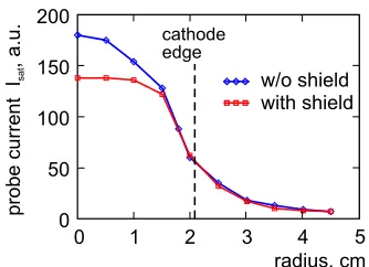
Fig. 8 Flattening of plasma density distribution using heat shield at cathode backside. Cross-field discharge: B=0.3 kG,
U=300 V,I=110 A.
plasma density in the magnetic flux tube connected to this spot. Thus the plasma density distribution can be probably made more uniform by changing the temperature distribu-tion at the cathode. In order to reduce the central tempera-ture maximum at the cathode, a 30 mm heat shield made of six layers of tantalum and graphite foils was installed at the center of the backside of the cathode to partially block the radiation from the heater spiral (see Fig. 7). The cathode with this heat shield was run in the direct and cross-field discharge modes. The effect of density profile flattening in the central region was observed only in the cross-field mode at high discharge voltages (see Fig. 8).
4. Conclusions
The axisymmetric plasma source with the hot disk cathode and the hollow anode was operated in two different discharge modes by changing the distribution of axial mag-netic field. When the cathode edge was in contact with the anode along the magnetic field lines, the plasma stream had almost uniform, but moderate density near the axis and the total width equal to the diameter of the anode bore. When the cathode-to-anode gap across magnetic field was large enough, the cross-field discharge required higher voltage, and the plasma density profile became almost Gaussian with the width close to the cathode radius. The plasma density profile in the cross-field discharge mode can be af-fected passively by changing the temperature distribution at the emitting cathode surface. These observations can be used in designing flexible plasma sources for linear devices for plasma-material interaction studies.
Acknowledgments
This work was supported by Russian Science Founda-tion (project No. 14-50-00080).
[1] D.M. Goebel, Y. Hirooka and T.A. Sketchley, Rev. Sci. In-strum.56, 1717 (1985).
[2] A. Kreter, C. Brandt, A. Huberet al., Fusion Sci. Technol.
[3] T.D. Akhmetov, V.I. Davydenko, A.A. Ivanov et al., Rev. Sci. Instrum.87, 056106 (2016).
[4] T.D. Akhmetov, V.I. Davydenko, A.A. Ivanov et al., AIP Conf. Proc.1771, 070003 (2016).
[5] A. Piel, Adv. Space Res.10(7), 7 (1990).
[6] J.-P. Boeuf and A. Smolyakov, Phys. Plasmas 25, 061001 (2018).