Conceptual Design and Development of an Indirect-cooled
Superconducting Helical Coil in the FFHR
Hitoshi TAMURA, Kazuya TAKAHATA, Toshiyuki MITO, Shinsaku IMAGAWA
and Akio SAGARA
National Institute for Fusion Science, 322-6 Oroshi-cho, Toki, Gifu 509-5292, Japan
(Received 7 January 2009/Accepted 14 July 2009)
The force-free helical reactor (FFHR) is a conceptual design of a heliotron fusion reactor being developed at the National Institute for Fusion Science. All the coils in the FFHR are made of superconductors. Several cooling schemes have been proposed for the helical coils; of these, indirect cooling is considered a good candidate. In this study, we investigated the possibility of using an indirect-cooled superconducting magnet for the FFHR. In parallel with this design study, we developed Nb3Sn superconductors, jacketed with an aluminum alloy, for
use in an indirect-cooled magnet. The results of performance tests of a sub-scale superconductor showed good feasibility for application in the FFHR helical coil. Stress distribution in the helical coil was also analyzed, and the stress and strain were confirmed to be within the permissible range.
c
2010 The Japan Society of Plasma Science and Nuclear Fusion Research
Keywords: large helical device, helical reactor, indirect-cooled superconducting magnet, Nb3Sn superconductor,
cable-in-conduit-conductor, stress analysis DOI: 10.1585/pfr.5.S1035
1. Introduction
Experimental results of the Large Helical Device (LHD) have revealed that an LHD-type helical reactor is well suited as a demonstration device for a fusion power plant [1]. The force-free helical reactor (FFHR) is a con-ceptual design of an LHD-type heliotron fusion reactor being developed at the National Institute for Fusion Sci-ence [2, 3]. The FFHR’s magnet system includes one pair of helical coils and two pairs of poloidal coils. All the coils are made of superconductors. Several cooling schemes, such as forced flow and indirect cooling, have been pro-posed for these superconducting helical coils. The for-mer, with a cable-in-conduit conductor (CICC), has been chosen in many large-scale experimental fusion magnets, such as the poloidal coils of the LHD, the main coils of ITER, Wendelstein 7-X, and JT-60SA, because of its me-chanical strength and electrical/thermal stability. However, forced flow cooling with a CICC requires a circulation pump to maintain pressure to a supercritical region of the coolant. Therefore, the length of the cooling path can be limited. For instance, the maximum cooling length in the ITER specification is 390 m. Modifications of the cool-ing or windcool-ing method are needed for a magnet whose conductor length is several times that of an ITER-class magnet. On the other hand, indirect cooling solves this problem because the electrical and cooling paths can be separated. Furthermore, an indirect-cooled superconduct-ing magnet is considered to have higher mechanical rigid-ity, since its structural components, such as the supercon-ducting strands, jacket, insulators, cooling panels, and coil
author’s e-mail: [email protected]
case, are completely in contact with each other.
In this study, we investigated the possibility of using an indirect-cooled superconducting magnet for the FFHR. In parallel with this study, we developed Nb3Sn
supercon-ductors, jacketed with an aluminum alloy, for use in the indirect-cooled magnet. The “react-and-wind” process can be applied in a large superconducting coil using this type of superconductor, since the jacketing can be done after heat treatment of the superconducting strands by friction stir welding (FSW [4]). The details of sample conductor development and test results of a sub-scale superconductor are also given.
2. Structure of the Coil
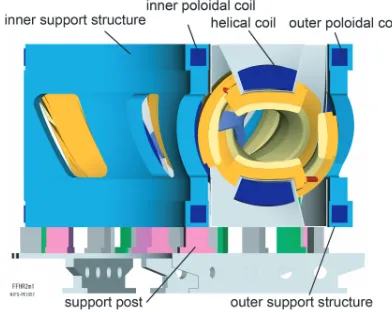
Figure 1 shows a schema of the cryogenic components in the FFHR. The major and minor radii of the helical coils
Fig. 1 Schema of the cryogenic components in the FFHR.
c
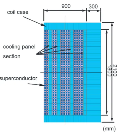
are approximately 14-16 m and 4 m, respectively. The total stored energy of the coils is 120 GJ. The electromagnetic force generated by these coils is sustained by inner and outer support structures. The magnetic field at the plasma center is 6.18 T. The cross-sectional dimensions of the he-lical coil were determined by considering the geometry of the plasma-facing components. Figure 2 shows a concep-tual design of the cross section of the helical coil, which is a rectangle 1.8 m wide and 0.9 m high. There are 432 superconductors (36 turns, 12 layers) made of Nb3Sn and
a jacketing material. An aluminum alloy was chosen as the jacketing material because it offers high thermal conduc-tivity and mechanical strength. The cooling panels were placed at every two or four turns of the winding. Each cooling panel consists of two parts: a cooling module and a case section. The cooling module is connected to coolant plumbing outside the coil cross section. The case section has to be build continuously with the superconductor so it will be a strength member, whereas the cooling module can be divided into several parts along the winding direc-tion. The total thickness of each cooling panel is 75 mm, and the superconductor is indirectly cooled by these pan-els. The coil is wound along the stainless steel (SS) coil case and covered with a lid. An LHD-type helical reactor does not require plasma current, so little AC loss occurs in the magnet. The heat load to the coil during reactor op-eration comes mainly from nuclear heating. Takahataet al.calculated the elimination of this steady-state heat load and showed that an aluminum jacket superconductor with a cooling panel could resolve this issue [5].
Fig. 2 Cross-sectional view of the conceptual design of the indirect-cooled helical coil.
3. Development of the Aluminum
Al-loy Jacketed Superconductor
3.1
Specification and fabrication process
The fundamental geometry of the superconductor is a 50 mm square, including insulation. Since the maximum magnetic field at the coil region is around 13 T, Nb3Sn
wires can be used. The operating current is 100 kA, and the overall current density is 40 A/mm2. Since the melt-ing point of aluminum alloy (933 K) is lower than the heat treatment temperature of the Nb3Sn wires (1000 K),
jack-eting must be done after heat treatment of the wires. We developed a conductor fabrication process, using an FSW technique that uses friction heating, to avoid a tempera-ture increase in the welding region. Since FSW is a solid-state joining process, the temperature at the welding re-gion is below the melting temperature of the material. In the case of the aluminum alloy, the temperature does not exceed 900 K. The superconducting wire is embedded in the aluminum alloy jacket with a solder material, and the lid is welded by FSW. The solder can be melted by heat-ing from the FSW, and it fills the void around the super-conducting wire. A prototype 10-kA-class 17-mm-square superconductor was made to demonstrate the fabrication process and the performance of the conductor. It showed a 19 kA transport current at 8 T and confirmed that although some degradation occurred in the critical current, it was not due to the fabrication process, but the difference in thermal contraction between Nb3Sn and aluminum alloy under a
change from room temperature to 4 K [5].
3.2
Reduced-size sample test
To confirm the thermal influence of the FSW and ex-amine an instance of bending deformation, 4.7-kA-class superconductors, made of Nb3Sn cable and aluminum
al-loy jackets using the same production process as the 10-kA-class sample, were manufactured. The packing fac-tor of the superconducfac-tor inside the aluminum jacket was increased from 60 % to 80 %. Figure 3 shows a cross-sectional view of the sample conductor and its dimensions. The following two samples were tested: (1) without bend-ing and (2) bent once along a rbend-ing with a radius of 150 mm and then bent back to the original straight shape (R150S).
Fig. 4 Critical currents of the reduced size superconductor, with and without bending.
Figure 4 shows the experimental results of current-carrying capacity tests. Open symbols indicate the critical current (definition; 1µV/cm) of the test conductor at 4.4 K; error bars represent the maximum and minimum magnetic field inside the conductor. The solid line indicates the critical current of each strand multiplied by 18 (the number of strands). We succeeded in carrying a current of 11 kA at 8 T with the sample R150S. This confirms that the criti-cal current was not affected by bending deformation. Fur-thermore, the critical current of sample R150S might be increased by a pre-bending effect [6].
4. Comparison with CICC
Here we simply compared the apparent rigidity of the indirect-cooled and CICC-type superconductors. Figure 5 shows models of the superconductors. The indirect-cooled superconductor has a 50-mm-square shape and a 32 mm square Nb3Sn superconducting region filled with solder.
The ratio of the superconductor to the solder is 8 : 2. The superconductor includes an 18-mm-thick aluminum alloy (6061 T6) and 1-mm-thick insulation. The CICC type has 90 kA of operating current with 480 superconductors made of Nb3Sn. The conduit is 1.6 mm thick, and the conductor
is embedded in the internal plate. Both components are made of SS. There is an insulator between the conduit and the internal plate.
The longitudinal rigidity was estimated according to the rule of mixture, using the area fraction of each struc-tural component. The transverse rigidity was calculated by modeling each conductor type with a finite element method (FEM) model. In this case, the plane strain model was adopted, and the rigidity was calculated from the re-sult of the reaction force against the forced displacement at the top of the conductor. In the indirect-cooled type, the material properties of the superconducting region were
se-Fig. 5 Rigidity evaluation model for the indirect -cooled (upper) and CICC (lower) superconductors.
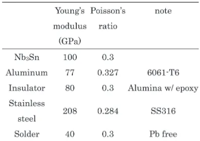
Table 1 Material properties of components.
lected according to the rule of mixture. On the other hand, the superconducting region in the CICC type was assumed to make no contribution to the mechanical rigidity in the transverse direction. The other components were treated as isotropic materials. The material properties of the com-ponents at a cryogenic temperature (4 K) [7–9] were used in the analytical model. The material properties used in the calculation are shown in Table 1.
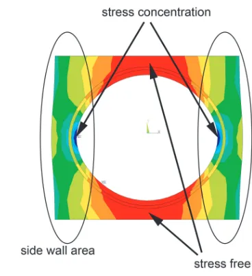
Fig. 6 Compressive stress distribution in the CICC.
CICC coil. Assuming that the case section in the cooling panel is made of SS316 and no stress concentration oc-curs, 20 % of the total cooling panel area can be used for the cooling module. The transverse rigidity of the indirect-cooled and CICC types were 79 and 56 GPa, respectively. Note that stress concentration may occur in the CICC, as shown in Fig. 6. The CICC with an internal plate resists transverse deformation only with the side wall area of the conduit and the internal plate.
5. Coil Rigidity Evaluation
5.1
Analytical model
The helical coil of the FFHR has a three-dimensional structure, with a change in its curvature in the toroidal an-gle. It is believed that a circular coil with an average cur-vature similar to that of an actual helical coil can be used to estimate the mechanical behavior of the coil [10]. We calculated the stress and strain distributions inside the coil to confirm the stress and strain levels. The average radius of curvature of the helical coil was 5.5 m at the center of its cross section. The cross-sectional structure of the helical coil, shown in Fig. 2, was used to create the FEM model. The radius from the central axis to the center of the coil cross section was set at the average curvature of the he-lical coil. The insulator used in the superconductors was assumed to be made of alumina ceramics and resin. An SS coil case, with a thickness of 300 mm at the top and 150 mm on both sides of the coil section, was used.
Because of an interaction between the magnetic field and the current flow, the magnetic field parallel to the cen-tral axis produced a hoop force, while the radial field pro-duced an overturning force. The electromagnetic force was applied as the body force by multiplying the current den-sity and magnetic field in every superconducting region to ensure that the electromagnetic force was precisely applied to the coil. The electromagnetic force considered here was
Fig. 7 Hoop stress distribution by the radial electromagnetic force.
Fig. 8 Hoop strain distribution by the radial electromagnetic force.
in the radial direction of the circular coil, since it generated a hoop force inside the coil. The hoop force is more eff ec-tive for the superconductor than the overturning force at a point of strength of the coil structure. Although the mag-netic field intensity was different at each cross section, an averaged magnetic field was applied at each superconduct-ing position along the circumference. Furthermore, a con-stant value was added to the averaged magnetic field so that the total hoop force in the cross section was equal to the maximum overall hoop force. ANSYS version 11.0 was used, and a three-dimensional axisymmetric solid element was adopted.
5.2
Results
compres-Fig. 9 Radial displacement inside the coil by the radial electro-magnetic force.
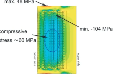
Fig. 10 Transversal stress distribution by the radial electromag-netic force.
sive stress toward the coil center region. The maximum in-plane shear stress in the insulation was 32 MPa. All stress and strain levels for each component were within the per-missible range.
6. Conclusions
In conceptual design studies of the FFHR, indirect-cooled superconducting helical coils have been proposed. Aluminum-alloy-jacketed Nb3Sn superconductors with a
cooling panel can prove the feasibility of this approach. The following results were obtained in this study: (1) A reduced-size sample of the aluminum-alloy-jacketed Nb3Sn superconductor showed good performance, and the
critical current did not degrade with bending. (2) The cool-ing panel requires a longitudinal rigidity of 163 GPa to pro-vide the same rigidity as a helical coil using CICC. (3) The indirect-cooled superconductor has a much higher trans-verse rigidity than the CICC. (4) Stress and strain distribu-tions in the indirect-cooled helical coil, investigated by the FEM model, were confirmed to be within the permissible range.
Acknowledgments
The authors thank Mr. M. Sugimoto of the Furukawa Electric Co., Ltd. for his efforts in developing a supercon-ductor for the candidate system. This work was supported by the National Institute for Fusion Science (08ULAA107, 08ULAA117).
[1] O. Motojimaet al., Fusion Eng. Des.81, 2277 (2006). [2] A. Sagaraet al., Nucl. Fusion45, 258 (2005). [3] A. Sagaraet al., Fusion Eng. Des.81, 2703 (2006). [4] C. J. Dawes and W. M. Thomas, Weld. J.75, 41 (1996). [5] K. Takahataet al., Fusion Eng. Des.82, 1487 (2007). [6] G. Nishijima et al., IEEE. Trans. Appl. Supercond. 16,
1220 (2006).
[7] Cryocomp software (Eckels Engineering and Cryodata Inc., 1997).
[8] D. Mann,LNG Materials and Fluids(National Bureau of Standards, 1977).
[9] N. Mitchell, Cryogenics45, 501 (2005).