Improving Heat Transfer in Falling Film Evaporators
in Food Industries
Rahaei, Neda; Jafari Nasr, Mohammad Reza*
+Islamic Azad University, Science and Research Branch, Chemical. Engineering Department, Tehran, I.R. IRAN
ABSTRACT: Falling film evaporators, due to their high heat transfer coefficients, low energy loss, rather a low holdup time, and th ability to handle high capacities have broad applications in food industries. Thus, this kind of evaporator is being used in the production of temperature sensitive compounds such as syrups. In this study, through modelling of the falling film evaporator with the use of Computational Fluid Dynamics (CFD) we have tried to investigate the effect of adding flow turbulator (baffles) on the inner side of the tubes and assess the key parameters for increasing the efficiency of the evaporator. The simulation was conducted using ANSYS FUENT (v 0.16.0). Results indicate that placing baffles would have a significant effect on increasing evaporator efficiency. The results of the parametric study showed that by installing baffles, the amount of juice evaporation rate can be increased, however, both the evaporator length and volume fraction can be reduced. The results showed that the heat transfer coefficient has increased from 10000 W/m2 °C in the case of the typical evaporator to 25000 W/m2 °C in the case of a baffled tube wall.
KEYWORDS: Falling film evaporator; Optimization; Simulation; CFD; Baffle.
INTRODUCTION
One of the widely used practices in the food industry is concentrating on fruit juice [1]. Basically, juice concentrating is carried out for achieving these goals [1, 2]: 1) Saving investment, as juice concentrating equipment will reduce the cost related to warehousing and storage. 2) Reducing transportation costs, as the volume and amount of transportable goods will be reduced significantly. 3) Due to reduced water activity, concentrated juice holdup will be relatively more than a fresh juice holdup. 4) As some fruits are available during certain seasons, concentrating and storing their juice will make their juice available in every season. 5) Reduced drying process limit which can be used for producing powder products in food industries.
Although methods such as reverse osmosis and freezing concentration could be employed, maybe the most favorite equipment in the food industry, particularly the dairy industry, for concentrating thermos-sensitive foodstuffs, is falling film evaporator [1, 3]. The evaporation process eliminates water from liquid food and is being used extensively at high rates. In food industries, thermal damage to the product’s quality has always been a concern, as the evaporation process is usually operated at low pressure and rather a low temperature [4]. Falling film evaporator, due to its short residence time, can produce a concentrated product with satisfactory nutritional characteristics [3]. They are very attractive mainly due to low evaporation temperature, and great
*To whom correspondence should be addressed.
+E-mail: nasrmrj@ripi.ir
heat transfer coefficient even at small film flow rates. In addition to the food industry, they are commonly used in chemical and petrochemical plants, refineries, and desalination [5].
Traditionally thermal processes are analysed via energy [6]. In a process, an efficient evaporator can reduce energy consumption, economic resources and dangers to the environment. Evaporator efficiency with the aim of increasing heat transfer can be improved by optimizing heat transfer surface area or evaporator wall [7]. In recent decades, many attempts have been made for recognizing the key parameters for increasing the heat transfer rate in the evaporators, in order to lower the capital and operating costs. One can find numerous experimental and theoretical research on the falling film evaporators in the open literature, varying from tube surface geometry, tube materials, tube size, operating fluid, liquid film flow rate, heat flux order, and the number of tubes.
Current techniques for improving heat transfer can be divided into 2 categories: Active methods, which need external forces like electricity, such as vibrating or rotational heat transfer areas which, due to high energy consumptions have not used so successful. Passive methods, which do not need to certain external forces, however in some cases external additives, are required. Heat transfer rates using passive methods can be increased in comparison to heat transfer rates in a simple plain tube [8].
Finned tubes application is one of the passive methods of improving heat transfer. For means of improving heat transfer in falling film evaporators, artificial sites are made such that nuclei boiling takes place at rather lower temperature difference, also film disturbance and heat transfer area increases. The main purpose of these methods is reducing evaporator size or in other words, increasing heat transfer and equipment efficiency. Flow turbulator (baffles) as one of the effecting means on heat transfer has been investigated and used in some cases [9]. Since the controlling resistance of these evaporators is mainly due to the falling film, their efficiency, can be improved by installing proper turbulators such as twisted tubes and rippling tubes [1].
Numerous attempts have been made for modelling hydrodynamics and heat transfer of falling film evaporators. Unfortunately, a general dependable model
for predicting the fluid flow and heat transfer in the falling film evaporators has not been obtained [10].
Simulation software and availability to calculate the falling film heat transfer, lead engineers to become interested in using this method to predict problems. Analysis of the process with the use of an accurately validated simulator is vital for lowering production costs and improving efficiency. Computational fluid dynamics is an irreplaceable tool in design, which could thoroughly investigate the process and determines the key variables [11].
In this study, following our earlier work [12], by modelling of the falling film evaporator using ANSYS FUENT (v 0.16.0) the effect of adding flow turbulator (baffles) on the inner side of the tubes is studied and the main variables, which may affect the efficiency of the evaporator are evaluated.
MODELING System Geometry
Usually, in falling film evaporators, for optimizing the evaporation process, the juice flows down as a thin layer on the wall while at the canter juice vapor will flow up. Fig.1 shows fluids flow schematics inside a typical evaporator. As seen in Fig.1, inside evaporator tube, there is a fluid layer on the wall, which absorbs heat from the wall and film evaporation begins. Flowing vapor outside the tube acts as a heat source and gets colder and condensed [13]. In the present work, fluid flow and heat transfer are only considered on the inner side of the tube, the effect of hot vapor outside the tube is considered as fixed temperature around the tube, and temperature difference between the wall and the juice saturation temperature is considered as a simulation input variable. The physical dimensions of the evaporator used for simulation are given by the experimental design used in previous work [14] and by comparing, experimental results and properties of the steel as tube material are listed in Tables 1 and 2, respectively.
Physical Characteristics of Fluids
Table 1: Experimental design parameters [14].
Parameter Value
Evaporator length L=2000mm
Evaporator efficient length Lfilm=2000mm
Inner diameter Dbrix=32mm
Tube material Stainless steel
Feed juice temperature Tbrix=363 ̊K
Wall and saturation temperature difference ΔT=8 ̊K
Table 2: Physical properties of steel walls [14].
Property Value
Density (kg/m3) ρ=8030
Specific heat capacity (J/kg.K) Cp=502
Heat conductivity coefficient (w/m2.K) k=16.27
Fig. 1: Falling film evaporator schematics.
Water evaporation in falling film evaporators, conducted at low temperature and vacuum pressure, due to juice sensitivity. In other hand, juice boiling point, according to below equation will be increased due to existing of solid particles in juice pulp:
BX B.P.E
100 BX
(1)
In equation (1), BX is Brix level and is a representative of solid particles in the juice. It should be
mentioned that, as the water evaporates, Brix level increases and this will result in increasing fluid viscosity and reducing of the heat transfer coefficient. Water vapor properties, which flow in the center of the tube, is shown in Table 4.
Mathematical Formulation
In this section, the governing equations of the flow are presented. First, the equations of two-phase flow are obtained, and then, the evaporation process is formulated.
Evaporator tube
tube upper plate
Vapor
Evaporator tube
Vapor condensation
tube lower plate
Juice concentrate Juice
Table 3: Thermo-physical properties of fruit juice.
Property Value
Density (kg/m3) ρ=1428.5-454.9X-0.231T
Specific heat capacity (J/kg.K) Cp=1424.34+2673.19X+2.446T
Heat conductivity coefficient (w/m2.K) k=0.0797+0.5238X+0.000580T
Viscosity (kg/m.s) µ=0.001003
Table 4: Thermo-physical properties of water at 363°K [14].
Property Value
Density (kg/m3) ρ=0.0831
Specific heat capacity (J/kg.K) Cp=1563.077+1.6037T+0.002932T2
Heat conductivity coefficient (W/m2.K) k=0.023
Viscosity (kg/m.s) µ=1.2e-5
Two-phase flow equations
For simulation of falling film in the tubes, the flow needs to be considered as two-phase. The first phase is vapor, which flows upward in the center of the tubes and the second phase is a liquid, which flows downward on the wall of the tube. In FLUENT software, the Volume of Fluid (VOF) model has developed to simulate multiphase flow behaviour. In the present study, the flow of the vapor and juice is considered to be laminar, which usually VOF is used for such flows. In this model, two sets of transport equations have been solved for each phase and by determining interface profile between two phases, the two-phase flow is investigated. The mass conservation equation could be written as below:
q q
q q q
1q t
(2)
q
n
p q q p
p 1
S m m
In equation (2), mp q and mq p are mass transfer rates
between two phases of q and p. In addition, q is the
volume fraction of phase q in p, which is computed by the following equation.
p 1 q
(3)
Equations of evaporation
To study juice evaporation from the tube inner surface, according to the temperature difference between
wall and fluid and also juice saturation temperature, here is considered to be 353 K, and can be computed by following equation [15].
v
qVv
ml v mv lt
(4)
In Equation (4), the subscript v represents the vapor phase, and subscript l shows the liquid phase. The symbol is the volume fraction of the vapor phase.
Equations of falling film
The falling film flows under the effect of external forces such as shear stress, gravity and surface tension. Reynolds number in laminar flow is computed using equation 5:
1 1
u D m
R e
4 D
(5)
Wherein D is the diameter of the tube (m), is fluid
density (kg/m3), is dynamic viscosity (kg/m.s),
1 m
Liquid mass flow rate (kg/s) and u1 is liquid superficial velocity (m/s). The transition limits of flow regime from laminar flow to ripple flow and turbulent flow are presented below:
1 11
L WL a
Re 0.61K (6)
1.06 0.333
WL T a
Where:
4
a 3
G
K
(8)
Which is surface tension and Ka is Kapitsa number. Falling film average thickness is and can be computed for each type of flows by the following equations:
Falling film average thickness according to Nusselt theory for laminar flow:
1 3 2R e 3
g
(9)
Falling film average thickness according to Kapitsa theory for rippling flow:
1 3 2R e 2 4
g
(10)
and for turbulent flow, falling film thickness is computed according to the following equations:
0.5
0.5Re 0 5
(11)
Where
Re 20 Ln 5 30 (12)
Re 4 3 2.5Ln 256 30 (13)
The overall heat transfer coefficient for the falling film can be determined using equation (14):
Q U
T A
(14)
Boundary conditions
Flow regime, information on inflow and outflow, solveing compatibility and use of an algorithm effect on the selection of boundary conditions. The selection of improper boundary conditions not only affects simulation precision; but also in some cases will result in slow convergence or even divergence.
In the present study, boundary conditions have been determined according to the physics of the problem. It should be reminded that the present problem is divided into two regions. A region where the juice flows as the falling film and a region where vapor flows in the center of the tube. It is a two-phase flow and related equations
need to be solved for these regions. Three types of boundary conditions are needed to be determined properly: 1) boundary conditions needed for solving fluid flow equations, 2) heat transfer and energy conservation 3) boundary conditions related to the two-phase flow. These boundary conditions are described as follows.
Boundary conditions for solving fluid flow equation For solving the Navier-Stokes equation, it needs to determine inflow, outflow and tube boundary conditions properly. For analyzing falling film phenomena, at the inflow cross section, 1 mm of radial length from the tube wall is considered for the known mass flow rate of juice, which enters the system. The rest of the tube cross section is considered for vapor entrance and its boundary condition is the initial velocity. At the outflow cross section, the boundary condition is outlet velocity. In addition, at the tube wall, no slip boundary condition is assumed.
The two-phase flow boundary condition
In order to solve the equation of each liquid and vapor phase volume fraction, the boundary conditions at both inflow and outflow must be determined. For this aim, at the cross section while the juice is flowing (a 1mm distance from tube wall) liquid volume fraction is considered unity. In addition, for the vapor entrance cross section (the distance between 1 mm from wall to tube centerline) water volume fraction is equal to zero.
Thermal boundary conditions
These boundary conditions could be categorized into inflow and tube wall boundary conditions. At the flow entrance for both vapor and juice, the constant temperature boundary condition was considered equal to the juice saturation temperature (363K). The wall boundary condition is set according to the data input (temperature difference between wall and saturation temperature). In the first step of the simulation, wall temperature is set to 8 degrees different from saturation temperature, which is equal to 371 K.
Simulation and validations
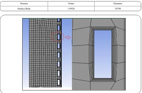
Table 5: Mesh information.
Domain Nodes Elements
Surface-Body 119928 56798
Fig. 2: Evaporator geometry.
generating geometry, the next step, generating mesh, was created using the aforementioned software. Since transport phenomena are more important in regions near the tube walls, the mesh cells near the walls and turbulators created in smaller sizes. This model is based on the turbulent model. The symmetry in the geometry allows limiting simulation to only half of the tube diameter using axisymmetric boundary conditions. This reduces both simulation time and computational cost. The mesh information is listed in Table 5. Fig. 2 shows the geometry of the evaporator and baffles.
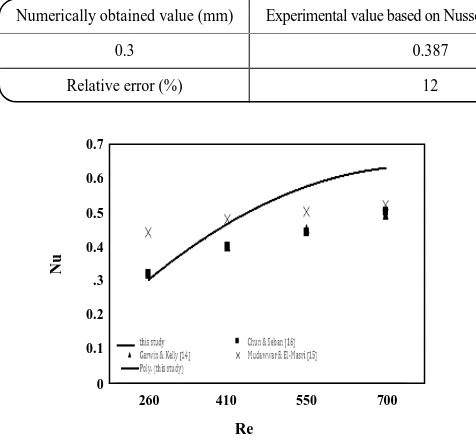
RESULTS AND DISCUSSION Model Validation
In order to validate the simulated model, the Nusselt dimensionless number in term of Reynolds number is plotted and compared to Grawin and Kelly [16], Mudawwar and El-Masri [17], and Seban experimental correlations [18] and related numerical data [14] in Fig. 3. The data points are illustrated by the dots in the figure.
The given Nusselt numbers in terms of Reynolds and Prantel numbers, presented here respectively [16-18]:
0.33 0.33
Nu 0.0302 Re Pr (15)
0.17
Nu 0.172 Re (16)
0.4
Nu 0.0364 Re (17)
As seen in Fig. 3, the model predicts the experimental data points and mimics the expected trend in an acceptable manner. The statistical evaluation of the model shows that the average error in comparison with the Mudawwar & El-Masri experimental correlation is 27%, in comparison with Seban equation is 28%, and in comparison, with Grawin & Kelly correlation is 16%, which are acceptable in general.
Table 6: Validating numerical method by comparing falling film thickness.
Numerically obtained value (mm) Experimental value based on Nusselt correlation (mm) Experimental value based on Kapitsa correlation (mm)
0.3 0.387 0.359
Relative error (%) 12 5
Fig. 3: Comparison of model predictions with the experimental correlations.
correlations. There are two main correlations for falling film thickness, first, which is obtained from Nusselt theory, assumes that the free interface of the gas and liquid is completely smooth [19]:
1 3 2R e 3
g
(18)
It should be mentioned that the falling film phenomena usually create turbulency and waves at the gas-liquid interface. Thus, in the case of small waves in the falling film, it is possible to use Equation (18) which is obtained from Kapitsa theory and in the case of having baffles this equation could be applied [19]:
1 3 2R e 2 . 4
g
(19)
A comparison between the thickness of the falling film obtained from the mentioned experimental equations and simulation results is conducted. The result of the comparison is given in Table 6.
By comparing the results of the numerical method and the results of the wavy free interface, the related error is almost 5%, which is acceptable.
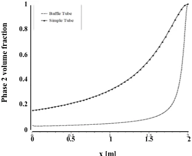
Comparing two-phase flow between the typical and baffled evaporator
In order to compare the liquid phase distribution along the tube of a typical wall with/without baffles, inputs and boundary conditions are considered the same in both states. The thickness of the fluid layer close to the tube wall has been determined by its flow rate, which in this study is less than 1 mm. As observed by comparing Figs. 4 and 5, the installation of turbulators would enhance heat transfer and resulted in the liquid to be evaporated faster; thus, the amount of liquid in the evaporator will be decreased.
For a better depiction of the falling film, juice volume fraction along the tube wall at initial, middle and final stages of the tube, for both in typical and baffled evaporators are presented in Fig. 6.
As shown in Fig. 6, in the inlet section, the volume fraction of the juice in both smooth and baffled tubes, at 1 mm distance from the tube wall is unit. As seen in Fig. 6, by moving toward the middle section of the tube a fall in the liquid volume fraction at a 1mm distance from the tube wall could be seen in both smooth and baffled tubes. Nevertheless, the decrease of liquid volume fraction in the baffled tube is considerably higher and it could be seen, by reaching the 0.75m distance from the inlet, the volume fraction is almost zero. This is occured while in the smooth tube, the liquid volume fraction in the outlet is about 0.2. It can be concluded that by the installation of baffles at the inner side of the falling film tube walls, there is a possibility to reduce evaporator length.
In order to present a better visual understanding of the velocity distribution in the tube, velocity contours and velocity vectors are presented for both cases in Figs. 7 and 8, respectively. As seen at downstream of the tube, gas velocity has become equal to falling film edge velocity, which considers the fluid flow, agrees with the results of previous works on the smooth and baffled tubes [14].
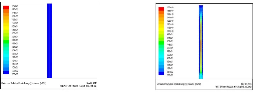
It is worth assessing the effects of the baffles in the turbulent flow regime. Fig. 9 shows the turbulency of both smooth and baffled tubes. As it can be seen baffles will increase turbulency which itself will result in more heat transfer.
Re
Nu
0.7
0.6
0.5
0.4
.3
0.2
0.1
0
Fig. 4: Liquid phase volume fraction contour along evaporator’s tube in common evaporator at the initial stage.
Fig. 5: Liquid phase volume fraction contour along an evaporator’s tube equipped by baffles.
Fig. 6: Liquid phase (juice) volume fraction plot along smooth and baffled evaporator wall.
Heat Transfer
Comparing temperature distribution in unbaffled (smooth tube) and baffled evaporators
The results of temprature distribution in both cases of smooth and baffled tubes are presented in the form of temperature contour plots and two dimentional gas-liquid interface temperature plots in Figs. 10 and 11, respectively.
These results indicate that as the fluid flows downstream in both tubes, the temperature rises, however in the case of the baffled tube, this temperature rise is almost instantaneous and sharp while in the smooth tube the temperature raises in gradually with respect to axial distance from the tube entrance. While the inlet temperature is 363 K for both tubes, the temperature rises to 371 K for baffled tube instantly, almost at the tube entrance, but for the smooth tube even at the outlet the temperature did not raise further than 367.9 K. This could be described that by adding baffles to the tube, the thickness of the thermal boundary layer would be decreased. In addition, the baffled tube has more heat transfer area.
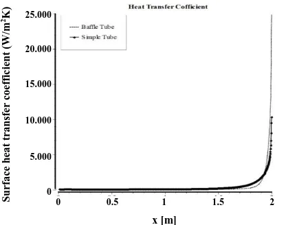
Comparing the heat transfer coefficient in typical and baffled evaporators
As was mentioned earlier, the main purpose of this study is increasing heat transfer by adding baffles on the inner wall of the falling film evaporator. In this manner, a competitive study has been conducted to compare the heat transfer coefficient in both cases. As seen in Fig. 12, the heat transfer coefficient has increased from 10000 W/m2 °C in the case of the unbaffled (smooth)
evaporator to 25000 W/m2 °C in the case of baffled wall
evaporator.
Parametric analysis
To show how the model has good potentials to provide valuable information on the key parameters of the evaporation process, three parameters, which were frequently focused in literature, were chosen for parametric study:
1- Evaporation temperature 2- Tube length
3- Temperature difference between wall and juice saturation temperature
The range of these variables is presented in Table 7. In the following sections, the detail on the investigation of each parameter will be presented.
x [m]
Pha
se
2
v
o
lu
me
f
ra
ct
io
n
1
0.8
0.6
0.4
0.2
0
Fig. 7: a) velocity contour along evaporator smooth wall at initial stage. b) Velocity contour along evaporator baffled wall at initial stage.
Fig. 8: a) Velocity vectors based on juice volume fraction along evaporator smooth wall at initial stage. b) Velocity vectors based on juice volume fraction along evaporator baffled wall at initial stage
Fig. 10: a) Temperature contour inside the tube along evaporator smooth walls at the initial stage. b) Temperature contours inside the tube along evaporator baffled walls at the initial stage.
Fig. 11: a) Gas-liquid interface temperature plot at the center line of the smooth tube along the axial length. b) Gas-liquid interface temperature plot at the center line of the baffled tube along the axial length
Fig. 12: Heat transfer coefficient in both cases of unbaffled (smooth) and baffled evaporator
Effect of evaporation temperature
Evaporation temperature may affect other parameters. At constant length (L=2m), constant temperature difference (ΔT=8 K) with constant feed flow rate (m=0.0167 kg/s), changing evaporation temperature will be changed the operating pressure. In addition, temperature boundary conditions at vapor, juice inlets will be changed, and due to the constant temperature difference, wall temperature will be changed. Fig. 13 shows the juice temperature profile on the evaporator wall as evaporation temperature changes for both smooth and baffled tubes. As it could be seen changing the evaporation temperature will have almost no effects on juice volume fraction.
x [m]
T
emp
er
a
tu
re
[
K]
365.5
365
364.5
364
363.5
363
0 0.5 1 1.5 2
x [m]
T
emp
er
a
tu
re
[
K]
378
376
374
372
370
368
366
364
362
0 0.5 1 1.5 2
x [m]
S
u
rf
a
ce
h
ea
t
tr
a
n
sf
er
c
o
ef
fi
c
ie
n
t
(W
/m
2K) 25.000
20.000
15.000
10.000
5.000
0
Table 7: The range of varying parameters for parametric analysis [2].
Parameters Range of values
Evaporation temperature (K) (in feed flowrate, tube length, constant temperature difference) 338,343,348,353
Temperature difference between wall and fluid saturation temperature (K) 366,368,371,373,378,381
Hot tube length (m) 1.2, 1.6, 2
Fig. 13: a) Effect of evaporation temperature on the liquid volume fraction in smooth tube evaporator with 2m length and 8 °K temperature difference. b) Effect of evaporation temperature on the liquid volume fraction in baffeled tube evaporator with 2m
length and 8 °K temperature difference
Effect of temperature difference
In order to investigate the temperature difference between wall and juice saturation temperature, evaporator length and evaporation temperature were considered to be constant and equal to 2m and 363K, respectively.
Fig. 14 shows the temperature distribution along the tube at different temperature difference between wall and juice saturation temperature, for both smooth and baffled tubes. It is obvious from the graphs that increasing wall temperature and consequently temperature difference between the wall and the juice saturation temperature will increase the outlet temperature. It is worth noting that the juice the typical evaporator with the smooth pipe will not reach the wall temperature even at the tube outlet. For example, when the tube wall temperature is 366 K and the juice feed temperature is 363 K, the outlet temperature of the juice will be 364.2 K and as this temperature difference increases, mentioned the difference in temperatures will also become serious. On the other hand, the juice temperature in the baffled tube reaches the tube wall temperature within the vicinity of the tube inlet.
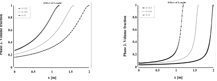
The effect of evaporator length
The evaporator length is an important parameter and affects the efficiency and cost of an evaporator. In order to investigate these parameters, three unbaffled (smooth) tube geometries and three baffled tube geometries considered with a length of 1.2, 1.6 and 2 m. The saturation temperature of 371 K and the constant temperature difference of 8 K has been considered for all geometries. Fig. 15 illustrates the juice volume fraction of the evaporator wall as evaporator length varies in terms of x-direction.
According to Fig. 15, it can be concluded that increasing the evaporator length results in a higher evaporation rate and decreased juice volume fraction on the wall. This could be related to a higher liquid holdup in the tube and the increase of heat transfer surface area, which finally results in a higher evaporation rate. It should be noted that the fluctuations in the volume fraction are related to falling film fluctuations.
As seen, in the case of the baffled tube all three cases approach the same outlet liquid volume fraction, near zero. As a result, it is possible to decrease the tube length
x [m]
Pha
se
2
.
V
o
lu
m
e
fr
a
ct
io
n
1
0.8
0.6
0.4
0.2
0
0 0.5 1 1.5 2
Pha
se
2
.
V
o
lu
m
e
fr
a
ct
io
n
1
0.8
0.6
0.4
0.2
0
0 0.5 1 1.5 2
Fig. 14: a) The effect of wall temperature on an unbaffled (smooth) tube with the juice saturation temperature of 363K. b) The effect of wall temperature on a baffled tube with the juice saturation temperature of 363K.
Fig. 15: a) The effect of Evaporator length on the juice volume fraction along the smooth tube wall. b) The effect of Evaporator length on the juice volume fraction along the baffled tube wall.
and at the same time keep the liquid volume fraction constant at the end of the tube. However, by improving heat transfer in the evaporator tube, the required potential to reduce evaporator sizes and dimensions can be provided.
CONCLUSIONS
This work was conducted with the aim of maximizing heat transfer by the help of ANSYS FLUENT software to analyze computational fluid dynamics. The geometry of the model was generated in 2D and axial symmetry, using a structural grid. In the first step of the simulation, wall temperature was set to 8 °K different from
the saturation temperature of the juice, which is equal to 371 K and feed flow rate of m=0.0167kg/s. After validation of the model with existing experimental correlations, it was shown in a parametric study of the falling film evaporator that by the installation of baffles inside the tube, it is possible to reduce evaporator length, increase juice evaporation rate, decrease the outlet volume fraction, and eventually reducing capital cost. The effect of baffles in reducing the liquid film thickness shows that concentrating orange juice using baffled evaporator could be one of the most efficient equipment in producing concentrated juice with keeping all of its desirable physical or chemical properties and nutrients.
Pha se 2 . V o lu m e fr a ct io n 1 0.8 0.6 0.4 0.2 0
0 0.5 1 1.5 2
x [m] 1 0.8 0.6 0.4 0.2 0 x [m] Pha se 2 . V o lu m e fr a ct io n
0 0.5 1 1.5 2
T emp er a tu re [ K] 369 368 367 366 365 364 363
0 0.5 1 1.5 2
x [m] T emp er a tu re [ K] 385 380 375 370 365 360
0 0.5 1 1.5 2
Symbols
A Total heat transfer area, m2
B.P.E Increased boiling point ˚BX Brix Cp Thermal capacity, J/kg.K
G Gravitational acceleration, m/s2
D Tube diameter, m H Fluid convective heat transfer coefficient, W/m2.K
H* Local convective heat transfer coefficient, J/kg
K Fluid conductive heat transfer coefficient, W/m.K Ka Kapitsa number
l Liquid phase l Evaporator length, m Lc Specified length, m
1
m Juice liquid mass flow rate, kg/s
Nu Nusselt number P Pressure, Pa Pr Prantel number Q Heat transfer flux W/m2
R Tube radius, m Re Reynolds number Tc Boiling liquid temperature, K
Ts Hot vapor temperature, K
Tsat Juice saturation temperature, K
ΔT Temperature difference between wall and liquid saturation temperature, °C U Overall heat transfer coefficient, W/m2.K
U1 Liquid superficial velocity, m/s
V Gas phase
Received : Mar. 27, 2018 ; Accepted : Jun. 18, 2018
REFERENCES
[1] Prost J., González M., Urbicain M., Determination and Correlation of Heat Transfer Coefficients in a Falling Film Evaporator, J. Food Eng., 73(4): 320-326 (2006).
[2] Chen H., Jebson R., Factors Affecting Heat Transfer in Falling Film Evaporators, Food Bioprod. Process., 75(2): 111-116 (1997).
[3] Frías-Esquivel, J., González-Alatorre, G., Díaz-Ovalle, C.O., Lesso-Arroyo, R., Ramos-Ojeda, E.,
Hydrodynamic Analysis of the Falling-Film Formation in Evaporators Using CFD Simulation, Food Bioprod. Process., 101: 56-67 (2017).
[4] Adomeit P., Renz U., Hydrodynamics of Three-Dimensional Waves in Laminar Falling Films, Int. J. Multiphase Flow, 26(7): 1183-1208 (2000).
[5] Ribatski G., Jacobi A.M., Falling-Film Evaporation on Horizontal Tubes—A Critical Review, Int. J. Refrig., 28(5): 635-653 (2005).
[6] Khoshrou I., Jafari Nasr M.R., Bakhtari K., Exergy Analysis of the Optimized MSFD Type of Brackish Water Desalination Process, Iran. J. Chem. Chem. Eng. (IJCCE), 36(6): 191-208 (2017).
[7] Chang H., Wave Evolution on a Falling Film, Annu. Rev. Fluid Mech., 26(1): 103-136 (1994).
[8] Liu S., Sakr M., A Comprehensive Review on Passive Heat Transfer Enhancements in Pipe Exchangers, Renewable Sustainable Energy Rev., 19: 64-81 (2013).
[9] Yu L.Q., Wasden F.K., Dukler A.E., Balakotaiah V.,
Nonlinear Evolution of Waves on Falling Films at High Reynolds Numbers, Phys. Fluids, 7(8): 1886-1902 (1995).
[10] Kouhikamali R., Abadi S.N.R., Hassani M.,
Numerical Investigation of Falling Film Evaporation of Multi-Effect Desalination Plant, Appl. Therm. Eng., 70(1): 477-485 (2014).
[11] Jafari Nasr M.R., Balaei A., Analysis of Fouling in HVAC Heat Exchangers by CFD. Iran. J. Chem. Chem. Eng. (IJCCE), 34(3): 51-60 (2015).
[12] Rahaei N., “Modelling of Heat Transfer Enhancement of Falling Film Evaporator in Food Industry by CFD”, Islamic Azad University, Sceince and Research Branch, Tehran, Iran (2016).
[13] Nguyen L.T., Balakotaiah V., Modeling and Experimental Studies of Wave Evolution on Free Falling Viscous Films, Phys. Fluids, 12(9): 2236-2256 (2000).
[14] Semnani R.M., Kaghazchi T., Experimental Determination of Heat Transfer Coefficient and Liquid Film Thickness in Concentration of Apple Juice, Using Falling Film Evaporator (2005).
[15] Ronkin V., Improvement in Operating Efficiency of Falling-Film Evaporators, Chem. Pet. Eng., 48(9-10): 540-545 (2013).
[17] Mudawwar I., El-Masri M., Momentum and Heat Transfer Across Freely-Falling Turbulent Liquid Films, Int. J. Multiphase Flow, 12(5): 771-790 (1986).
[18] Chun, K.R., Seban, R.A., Performance Prediction of Falling-Film Evaporators, J. Heat Trans., 94(4): 432-436 (1972).
![Table 2: Physical properties of steel walls [14].](https://thumb-us.123doks.com/thumbv2/123dok_us/8448300.1704091/3.595.55.543.141.560/table-physical-properties-steel-walls.webp)
![Table 4: Thermo-physical properties of water at 363°K [14].](https://thumb-us.123doks.com/thumbv2/123dok_us/8448300.1704091/4.595.54.545.98.304/table-thermo-physical-properties-water-k.webp)
![Table 7: The range of varying parameters for parametric analysis [2].](https://thumb-us.123doks.com/thumbv2/123dok_us/8448300.1704091/11.595.58.531.91.360/table-range-varying-parameters-parametric-analysis.webp)