Simulation Study of Ignition and Burn Characteristics of Fast
Ignition DT Targets
Tomoyuki JOHZAKI, Kunioki MIMA and Yasuyuki NAKAO
1)Institute of Laser Engineering, Osaka University, 2-6 Yamada-oka, Suita 565-0871, Japan 1)Department of Applied Quantum Physics and Nuclear Engineering, Kyushu University, 744 Motooka,
Fukuoka 819-0395, Japan
(Received 17 April 2007/Accepted 6 July 2007)
The ignition and burn properties of fast ignition DT targets are evaluated for various-sized core (ignition experiment∼high gain) on the basis of two-dimensional (2D) burn simulations. A core size ofρR≥2.0 g/cm2 is required to achieve explosive burning and then high gain. When the core size is smaller, the target gain drops sharply as core size decreases. Assuming the energy coupling efficiencies from laser to core of 5 % for implosion and 30 % for heating, a target gain of∼170 is obtained with a 1 MJ implosion laser and a 70 kJ heating laser, under optimum heating conditions (10 ps duration, 15µm spot radius, and 1.0 g/cm2heating depth). This requires a very high intensity heating laser (∼1×10²¹W/cm2). In accordance with a scaling for temperature of fast electrons generated by long-duration intense lasers, such a intense laser will generate fast electrons having suitable stopping range for efficient core heating. The sensitivities of ignition condition and gain performance to heating conditions, and the influence of high-Zions contained in a foam layer on ignition and gain performance are also discussed.
c
2007 The Japan Society of Plasma Science and Nuclear Fusion Research
Keywords: fast ignition, 2D burn simulation, ignition requirement, gain curve, heating pulse dependence, foam influence
DOI: 10.1585/pfr.2.041
1. Introduction
In fast ignition (FI) scheme [1], where an ultra-intense short-pulse laser rapidly heats an imploded core up to ig-nition temperature, high gain is expected with small driver energy, compared with conventional central spark ignition scheme.
For FI scheme, Atzeni [2] evaluated the ignition con-dition on the basis of two-dimensional (2D) simulations for precompressed DT cores and obtained scaling laws for the ignition energy, power, and intensity. However, the com-pressed core size was assumed to be significantly larger than the size of heating region. In addition, the gain perfor-mance was evaluated using the above ignition conditions and a simple formula for burn-up ratio [2, 3]. Application of those scaling laws, therefore, might be limited to such large targets.
At Institute of Laser Engineering (ILE), Osaka Uni-versity, high energy coupling efficiency from the heating laser to the imploded core and resultant core temperatures of∼1 keV were achieved using the cone guide targets in the Gekko XII–petawatt laser experiments [4]. As the next step, 10 kJ/10 ps Laser for Fusion Experiment (LFEX) for Fast Ignition Realization EXperiment phase-I (FIREX-I) is under construction [5]. A conceptual design of a laser fu-sion reactor based on FI, “KOYO-FAST” [6], has also been investigated. The compressed core size in FIREX-I will be
author’s e-mail: [email protected]
smaller than the MeV-electron range. The burn property of a small core expected in FIREX-I is different from that of a large-sized high-gain core. To understand the potential of FI and to make the research road map to approach fu-sion reactor, it is necessary to evaluate the ignition require-ments and gain performance for targets of sizes ranging from small (experimental class) to sufficiently large (high gain class).
Previously, we evaluated target gains for various sizes of compressed DT cores (core density ofρ = 300 g/cm3 and an isentrope parameter of α = 2) on the basis of parametric 2D burn simulations [7]. An evaluation for
α = 3 was also done. In the present paper, we show the ignition and burn dynamics of FI targets from ignition-experiment-grade cores to high-gain cores. In Sec. 2, we briefly describe the model of 2D burn simulation code “FIBMET” (Fusion Ignition and Burn code with Multiple Energy Transport) and the simulation setup. Section 3 de-scribes the simulation results. Sections 3.1-3.2 discuss the core-size dependences of ignition and burn performances and compare the results with previous studies. Section 3.3 evaluates the heating pulse parameter dependences for a high-gain target. The influence of foam material is evalu-ated in Sec. 3.4. Section 4 presents the conclusion.
c
2. Model Description
2.1
Simulation code FIBMET
The Simulation code FIBMET [7] is based on 1-fluid 2-temperature Eulerian hydrodynamic code, written in 2D cylindrical coordinates (r,z) with axial symmetry. In this code, the Thomas-Fermi and ideal gas models are em-ployed for the electron and the ion equations of state, respectively. The energy conservation equation consid-ers electron thermal conduction, radiation effect, fusion-product heating, and external fast electron heating. Elec-tron conduction is treated by the flux-limited Spitzer– Harm’s diffusion model. Radiation effect is evaluated by a 1-group flux-limited diffusion model. The radia-tion interacradia-tions considered here are the bremsstrahlung, the inverse-bremsstrahlung and the Thomson scattering. As for fusion reactions, T, D (two branches) and D-3He reactions are considered. The energy transport of 3.52 MeV alpha-particle is calculated by a multi-group, naturally flux-limited diffusion model [8, 9]. The produc-tion rates of other charged particles are much smaller than that of the DT alpha-particle; therefore, these particles are treated by a simple local/instantaneous deposition model. Neutron heating is not essential in DT fuel burning [10], and is neglected here. The FIBMET adopts two meth-ods for dealing with fast electron heating. One is a sim-ple model, adopted by Atzeni [2] and Slutz [11], where the core heating rate is numerically given and added to the en-ergy equation for bulk electrons. The other, more accu-rate, method treats fast electron transport in the core with a 2D relativistic Fokker–Planck (RFP) code [12, 13]. For the parametric study, however, the 2D RFP part is too expen-sive, because it requires 5D calculations (2D in real space and 3D in momentum space). Therefore, we adopt the sim-ple heating model.
2.2
Simulation setup
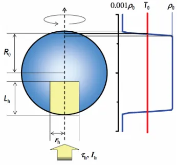
Although implosion dynamics and dense core forma-tion are important issues, especially for cone-guided tar-gets [4], they are not discussed in the present study. At the beginning of the simulation, uniformly-compressed sta-tionary DT plasma spheres are assumed as imploded core profiles. In setting the initial core profiles, we assumed 5 % energy coupling efficiency (ηi) from implosion laser energy (EL,i) to the core internal energy (Eint), and also
assumed a density ofρ = 300 g/cm3 and isentrope pa-rameter (the ratio of the fuel pressure to the Fermi pres-sure) ofα = 2 (or 3). The value of Eint is evaluated by (4π/3)R3α(3/5)n
eεF, whereR,ne, andεF are the radius, the electron-number density, and the Fermi energy of the compressed core, respectively. For a givenEL,iandηi, the core size becomes smaller asαincreases. The simulations were performed for several cores with different sizes (igni-tion experiment∼high gain) listed in Table 1.
The core heating process is also crucial. The clarifica-tions of the detailed physics of fast electron generation by
Table 1 Implosion laser energies and the corresponding com-pressed core sizes.
Core Type EImplosion Laser L,i[kJ] (ηi=5%)
ρR[g/cm2]
α=2 α=3
S1∗1 10 0.69 0.61
S2 25 0.97 0.85
S3∗1 50 1.23 1.07
D1∗2 160 1.59 1.38
H1∗3 560 2.64 2.31
H2∗3 960 3.33 2.91
*1 S1 and S3 correspond to FIREX-I and -II class cores. *2 D1 corresponds to fusion-burn demo class.
*3 H1 and H2 correspond to high gain cores.
Fig. 1 Schematic view of core profile at the beginning of simu-lations, and the heating region.
ultra-intense laser and its energy transport into the dense cores will lead to the optimization of core heating pro-cesses and determination of core heating efficiency. On the other hand, simulations using the simple heating model are important for the evaluation of ignition and burn dynam-ics, and determining the requirements for ignition and high gain in FI. For core heating, therefore, we simply assumed uniform heating rates [W/kg] for bulk electrons within the cylindrical region (the spot radiusrh [µm] and the opti-cal depthρLh =
Lh
0 ρdz[g/cm
2]) at the edge of the com-pressed core, with a duration ofτh [ps]. The core profile and the heating region are illustrated in Fig. 1.
3. Results and Discussion
3.1
Core-Size dependence of ignition and
burn performance
and 1 g/cm2—almost the same as a sphere with a radius of 3.52 MeV alpha-particle range. The pulse duration is fixed atτh = 10 ps. These are close to the optimum val-ues to minimize the ignition energy [2]. The heating pulse intensitiesIL[W/cm2] (the corresponding heating energies Eh[kJ]) are 1.0, 2.6, and 2.6×10²⁰W/cm2(7.1, 18.4, and 18.4 kJ) for S1, S3, and H1 cores.
The size of the S1 core (0.7 g/cm2) is comparable to the heating region assumed here. The bulk ion is heated through electro–ion temperature relaxation during the heating pulse injection, and its temperature rises con-tinuously up to about 10 keV. After external heating, how-ever, the core density and temperature decrease rapidly due to expansion since the surrounding cold region
con-Fig. 2 Fusion output power as a function of time from S1, S3, and H1 cores. The heating energies for each core are 7.1, 18.4, and 18.4 kJ, respectively. The heating pulse dura-tion is 10 ps.
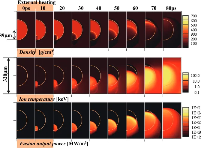
Fig. 3 Temporal evolution of fusion burning, obtained for an H1 core (ρR=2.6 g/cm2) with
a heating pulse ofIh=2.6×10²⁰W/cm2,τh=10 ps,rh=15µm andEh=18 kJ.
fining the heated region does not exist. Thus, fusion output power begins decreasing. For such small targets, explosive burning is never expected. In this case, the tritium burn-up rate (BT) of 0.64 % was obtained. This feature is so-called “driven ignition” [14] and expected in FIREX-I.
In the case of the S3 core, the core size (1.2 g/cm2) is larger than the external heating region, and then cold fuel surrounds the heating region. If the heating energy is sufficiently large, alpha-particle self-heating causes the core temperature to increase even after the external heating stops. The burn wave then propagates into the cold region as a deflagration wave, which sustains an increase in fusion output power. The core size is, however, not sufficiently large to achieve explosive fusion burn. The resultingBT is 4.7 %. This burn property is so-called self-ignition [14] and expected in FIREX-II.
3.2
Gain curve
As shown in the previous section, the burn properties depend on the core size. For further evaluation, we per-formed simulations for six cores with different sizes with
α = 2 and 3 (listed in Table 1), by varying the heating pulse energy. Here, the values ofrh,ρLh, andτhare fixed as 15µm, 1 g/cm2, and 10 ps, andI
h was varied to maxi-mize the target gainQfor each core. The target gainQis defined asQ = EF/(EL,i+EL,h), where EF andEL,h are the fusion output energy and the heating laser energy, re-spectively. To estimate the target gain, energy coupling efficiencies from laser to core were assumed asηi = 5 % for implosion, andηh =30 % for the following core heat-ing. (Such high coupling in core heating is expected in cone-guided targets [4].)
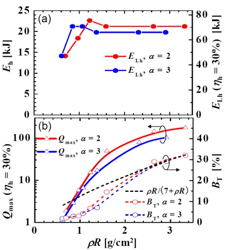
Figure 4 shows plots of the heating energy required to achieve the maximum gainQmaxfor each target, the max-imum gainQmaxobtained, and the corresponding burn-up ratioBT as a function of core size. The heating laser en-ergyEL,h (ηh = 30 %) is also shown on the right axis in Fig. 4 (a). The points from right to left correspond to the results obtained from the H2 core to the S1 core. A core size ofρR > 2 g/cm2 andEh > 20 kJ (EL,h > 60 kJ) are required for high gain. Because the compressed core tem-perature decreases for a fixed density, the ignition laser en-ergy is slightly enhanced asαdecreases. For evaluation of BT, a simple formula,
Fig. 4 Core-size dependences of (a) heating energyEh(and the
corresponding laser energy (ηh = 30 %)) required to
achieve the maximum gainQmax for each target and (b)
the correspondingQmaxand the burn-up ratioBT. BT
es-timated using Eq. (1) is also plotted.
BT= ρ R HB+ρR,
(1)
is widely used, whereHB =7 g/cm2. In their gain estima-tion for FI targets, Atzeni [2] and Tabaket al. [3] used this formula in their gain estimation. To check the validation of applying this formula to FI, Atzeniet al. [15] performed burn simulations, and found that the ignition threshold is
ρR = 1−1.5 g/cm2. We obtained similar results. When
ρR > 2.0 g/cm2, Eq. (1) agrees well with theB
T obtained from detailed simulations. BTdepends only onρR, not on
α.
In Fig. 5, Qmax is plotted as a function of total laser energy,EL,tot =EL,i+EL,h. The open circles correspond
toQmaxobtained for each core, except for the lowest gain points. The lowest gain point for each αvalue was ob-tained from the S1 core, by assumingEL,h =10 kJ which is the FIREX-I heating laser energy. In accordance with the burn properties described in Sec. 3.1, the region of EL,tot < 40 kJ is the driven ignition region, where ex-ternal heating is dominant, and Q < 1. The region of 40 kJ < EL,tot < 200 kJ is the self-ignition region where the self-heating of alpha-particles is effective, andQ=1∼ a few tens. High gain is achieved with EL,tot > 200 kJ. Forα =2, a target gain ofQmax = 175 is obtained with EL,tot ∼ 1 MJ. In conventional central hot spark ignition, a laser energy of a few MJ is required for such high gain. With increasingα, the implosion laser energy required for generating the same size core increases, which leads to loweringQmax, especially in the high-gain region. In the present case, the gain becomes∼4/7 in the high-gain re-gion whenαincreases from 2 to 3. For high gain, there-fore, low-isentrope implosion is also required.
In Fig. 5, we plotted a limiting gain curve evaluated by
Fig. 5 Maximum gainQmax as a function of total laser energy,
EL,tot = EL,i+EL,h. The red and blue solid curves
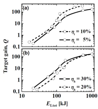
Fig. 6 Target gain dependence on coupling efficiencies between laser and core. (a) Dependence on the coupling of im-plosion laserηiwhereηh =30 % and, (b) dependence on
the coupling of heating laserηhwhereηi=5 %. (α=2
cores).
Atzeni [2],
G∗=18000η7i/6η0h.24
EL,totMJ
α3 7/18
×(EL,totMJ)0.018,
(2)
where the ignition energy was evaluated on the basis of numerical simulations for a sufficiently large core and the burn-up ratio was evaluated using Eq. (1). Thus, the limit-ing gain curve is not appropriate for a small core region, such as the driven ignition and self-ignition regions, al-though it agrees well with the present simulation results in the high-gain region.
In the above discussion, we assumedηi=5 % andηh
=30 % for gain estimation. However, these values have not been proved in practice. The gain sensitivities to the coupling efficiencies were checked.
In Fig. 6 (a),Qmaxevaluated forα=2 is plotted as a function of EL,totforηi =5 and 10 %, where the heating coupling is fixed asηh =30 %. Ifηidoubles, half the im-plosion laser energy is needed to generate the same core (or the core volume becomes twice as large with the same implosion laser energy), which enhances the target gain. In the low-gain region, whereEL,i ∼ EL,h, gain enhance-ment resulting from an increase inηi is not remarkable. In contrast, in the high-gain region, where EL,i EL,h,
the gain enhancement is significant. For instance, for EL,tot∼600 kJ,Qmax =143 forηi =5 % andQmax=327 forηi=10 %.
In Fig. 6 (b),Qmax, evaluated forα = 2 by assuming
ηh =20 and 30 %, is plotted as a function ofEL,tot, where
the implosion coupling is fixed asηi=5 %. In the low-gain region (EL,tot<200 kJ) whereEL,i∼EL,h, the reduction in Qmaxdue to decrease inηhis clear. In the high-gain region,
whereEL,i EL,h, it slightly affects gain performance, though the reduction inηh increases the heating laser en-ergy (ηh=20→30 %,EL,h=70→100 kJ).
3.3
Heating pulse dependence in high-gain
target
To achieve the high gain required for a fusion reac-tor (Q > 100), the required heating energy isEh ∼ 21 kJ (shown in Fig. 4), which corresponds to laser energy of EL,h = 70 kJ (ηh = 30 %). The above gain estimation is based on the simulations assumingrh =15µm, ρLh = 1 g/cm2, andτ
h =10 ps. The heating depth is determined by the generated fast electron temperature. If the fast elec-tron beam and the heating laser have the same spot and duration, the beam and laser intensities (Ih andIL,h) are
3×10²⁰ and 1×10²¹W/cm2, respectively. The effective temperature of fast electrons generated by a relativistic in-tense laser is generally evaluated using simple scaling [16]; Th=0.511 (γeo−1) [MeV], (3) whereγeois the electron relativistic factor in the laser field (γeo =
1+IL,hλ2L,h/1.37×1018,λL,his the laser wave-length [µm]). The averaged range ρλh of fast electrons having temperatureThis approximated by [15]
ρλh≈0.6Th[g/cm2]. (4)
Using these relations, the heating depth of fast electrons, generated by the heating laser is
ρLh≈0.3
1+ IL,hλ 2 L,h 1.37×10¹⁸ −1
[g/cm2]. (5) ForIL,h =1 ×10²¹ W/cm2, the heating depth evaluated using Eq. (5) is 8.8 g/cm2, which is much larger than the value assumed above and also the optimum depth for igni-tion (∼1.2 g/cm2[2]). Thus, if the fast electrons have the temperature scaled by Eq. (3), the laser intensity should be lower to shorten the fast electron range.
Eq. (3) provides simple ponderomotive scaling for laser–plasma interaction (LPI) at the critical density. In FIREX, and the subsequent DEMO and commercial re-actors, the heating pulse duration is 10 ps or longer. For such long-pulse intense lasers, the low-density pre-plasma on the cone inner surface is pushed by strong ponderomo-tive force, and the density profile steepens in an early stage of the main pulse irradiation [17, 18]. Then, the heating pulse directly interacts with a dense plasma. On the ba-sis of 2D collisional PIC simulations, Sentokuet al. [19] showed that, in this situation,Th is drastically decreased without reducing the coupling efficiency from laser to fast electrons, and derived a new scaling forTh;
Th=0.511γeo−1 γ
eonc ne,LPI
[MeV], (6)
wherene,LPI is the electron number density at the LPI re-gion. Using this scaling,Th is reduced by
γeonc
after the density profile steepens. For instance, when the heating laser withIL,h=1×10²¹W/cm2interacts directly with a solid Au cone (Z =50), where thene,LPI=2930nc, the fast electron temperature isTh =1.44 MeV. The range of those electrons is 0.6Th =0.87 g/cm2, which is slightly shorter than the optimum value. One way to increase the heating depth is to use higher intensity lasers. Another is to use a low density material for generating fast electrons. By attaching a low density material, such as a foam Au [20], on the cone inner surface, we can control the fast electron temperature and the heating depth without changing laser intensity.
The realization possibility of heating pulse parame-ters assumed above has not been clarified. In laser-cone interaction, fast electrons are generated with a certain an-gular spread (e.g., an opening half-angle of 22.5 degrees (FWHM) is observed in cone experiments [4]). The heat-ing spot size is therefore determined by the cone tip size, the angular spread of fast electrons, the cone tip size, and the distance between the cone tip and the edge of the dense core, if we neglect the pinch and divergence of elec-tron beam during propagation. For heating pulse duration, Nakamura et al. [21] performed 2D PIC simulations for laser-cone interactions, and observed longer electron beam emission from the cone tip than the duration of the irra-diated laser. This means that the core heating time is not determined solely by the duration of the heating laser. To evaluate the sensitivities of ignition conditions and gain performance to the heating pulse shape and the heating depth, we performed the simulations for the H2 core with
α=2 by varyingρLh,rh, andτh. Heating depth
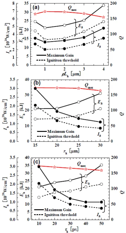
When the energy of fast electron is so high, the range is longer than the optimum heating depth (1.2 g/cm2[2]). In this case, larger heating pulse intensity and energy are required than the optimum values. Figure 7 (a) shows a plot of theρLhdependences. The duration and spot size of the heating pulse are fixed atτh =10 ps andrh =15µm, respectively. If the heating depth becomes larger than the optimum value, more energy is required for heating the ad-ditional region. Compared with theρLh = 1 g/cm2 case, IhandEh required for ignition andQmax are slightly high forρLh = 2 g/cm2, and Qmax decreases a little. If ρLh becomes three times longer, the Ih and Eh required for Qmaxincrease by 20 % andQmax(ηh =30 %) decreases by only 3.6 %. On the other hand, if the heating depth be-comes shorter than 1 g/cm2, the size of heating region be-comes smaller than the optimum value determined by the 3.52 MeV alpha-particle range. In addition, the portion of the heated region boundary facing the low density coronal plasma increases, which increases the energy loss due to expansion into the low density region. Thus, the increases inIhandEhrequired for ignition and the decrease inQmax with decreasingρLhare remarkable compared with deeper core heating.
Fig. 7 Heating pulse dependence of ignition and gain perfor-mance for the H2 core (α=2). Dependence on (a) depth
ρLh, (b) spot sizerh, and (c) durationτh.
Spot radius
The pulse intensity is proportional to r−h2, therefore, largerrh leads to intensity reductions. However, the heat-ing region becomes larger than optimum, and the energy loss due to expansion increases, so the required heating en-ergy might increase. In Fig. 7 (b), we plottedIhandEh, re-quired for ignition (broken lines) and forQmax(solid lines), and also plottedQmax(ηh=30 %) as a function ofrh, where
τhandρLhare fixed at 10 ps and 1.0 g/cm2. With increas-ingrh, the heating pulse intensities required both for ig-nition andQmax decrease, althoughEh increases slightly; whenrh increases from 15 to 25µm, Ihrequired forQmax becomes less than half (1.3×10²⁰W/cm2) andE
satu-rated, and the enhancement inEh is remarkable. Thus, the spot radius is required to be smaller than 25µm.
Pulse duration
Lengthening the pulse duration also reduces the heat-ing pulse intensity. However, defects resultheat-ing from expan-sion of the heated region (i.e., the energy loss due to ex-pansion and the decrease in density) become large, which increases theEh requirement. In Fig. 7 (c), we plottedIh andEh, required for ignition (broken lines) and for Qmax (solid lines), and also plottedQmax(ηh =30 %) as a func-tion ofτh, where rh =15µm andρLh = 1.0 g/cm2. An increase inτhdecreases the heating pulse intensitiesIh re-quired for ignition andQmax, and requires a slightly larger Eh. In addition, the time taken to reach explosive burning becomes long. During this transition time, the fuel gradu-ally disassembles and its size (ρR) becomes smaller, which results in a decrease in BT. The reduction in Qmax with increasingτh, thus, is mainly due to the core disassembly. The reduction in heating pulse intensity with increasingτh is saturated whenτh >30 ps, which results in monotonic increase of heating energy. Thus, the pulse duration should be shorter than 30 ps.
The values ofIhandEhrequired for ignition are sensi-tive to heating pulse parameters, as shown in Fig. 7. Those sensitivities are almost the same as the previous ones [5]. The values ofIh andEhrequired forQmax are larger than those for ignition by 27 to 54 %. The value ofQmaxis not as sensitive to heating pulse parameters becauseEL,iEL,h.
We performed simulations for the H2 core by assum-ing a large spot and a long duration, such asrh = 25µm andτh = 30 ps, to reduce the beam intensity. The heat-ing depth is assumed to beρLh = 2.0 g/cm2 We obtained that the required heating pulse intensity and energy are 5×10¹⁹W/cm2and 30 kJ for ignition, and 7×10¹⁹W/cm2 and 41 kJ forQmax. Whenηh = 30 % (20 %), the corre-sponding heating laser energy is 98 kJ (147 kJ) for ignition and 137 kJ (206 kJ) forQmax =155 (146)—twice that of the optimum heating case (rh = 15µm, τh = 10 ps, and
ρLh = 1.0 g/cm2). These results show that in a practical case, a heating laser of 150 to 200 kJ is required for suc-cessful burning in FI.
3.4
Foam e
ff
ects
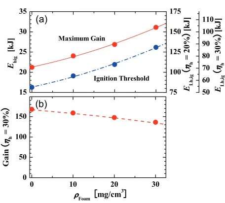
In the near future, foam targets are planned for use in DT experiments (such as FIREX-I [5]) and also in the reactor design of KOYO-FAST [6]. In FIREX-I, Re-sorcinol Formaldehyde–Phloroglucinolcarboxylic acid and Formaldehyde, (C8H6O2)2-(C7H5O4) (RF-PF) foam is one candidate for foam material [22]. A foam density of 100 mg/cc and a thickness of 7µm have been achieved, and further development is ongoing. Using a foam target, the middle-Zions such as carbon and oxygen are mixed in the compressed core. These ions enhance radiation loss from the heated region, which will make the ignition conditions more severe and reduce burn performance.
Fig. 8 Influences of RF-PF foam on ignition and gain of the H2 core (α=2). (a)Ehrequired for ignition (blue) andQmax
(red) and (b)Qmax(ηi=5 % andηh=30 % assumed) as a
function of foam density at the solid stateρfoam. The right
axes in (a) show the corresponding heating laser energies.
To evaluate the allowable density of the RF-PF foam, we performed simulations for the H2 core (α=2) by vary-ing the foam density at the solid state from 0 to 30 mg/cc. The heating pulse parameters are fixed at γh = 15µm,
τh=10 ps, andρLh=1.0 g/cm2. Figure 8 shows (a) heat-ing energy required for ignition and Qmax, and (b) Qmax (whereηi=5 % andηh = 30 % are assumed) as a func-tion of foam densityρfoam at the solid state. Forρfoam = 30 mg/cm3, E
h required for ignition (for Qmax) increases by 60 % (47 %) compared with pure DT, andQmax is re-duced by 20 %. This means that the influence of foam is more significant on the ignition requirement than gain per-formance, and the allowance of foam density is determined by the limitation of the heating laser. If the increase inEL,h resulting from the foam material is limited within 30 %, the foam density should be smaller than 20 mg/cm3, and maximum gain is reduced by 10 %.
4. Conclusions
On the basis of parametric 2D burn simulations for highly compressed DT cores (ρ = 300 g/cm3), the ig-nition requirement and gain performance were evaluated for cores of various sizes (ignition-experiment-grade to reactor-grade); these results were compared with previous studies. For achieving sufficiently high burn-up ratio (more than 20 %), a core size of ρR > 2.0 g/cm2 is required. For such large cores, the ignition requirement and the gain curve obtained in the present study agree well with previ-ous evaluations [2]. The target gain is sensitive toηiandα in the high-gain region, and is sensitive toηhin the ignition experiment region.
parameters to ignition and burn performance, and the influ-ence of foam material for a reactor-grade core. For an opti-mum pulse, minimizing heating energy for a given heating depth, i.e., τh = 10 ps andrh = 15µm, requires a very high intense pulse (more than 3×10²⁰W/cm2) for suc-cessful burning. If the heating laser has the same spot and radius as the heating pulse, a laser intensity>1021W/cm2 is required (ηh=30 %). In accordance with the new tem-perature scaling for fast electrons generated by long pulse heating laser, such a high intensity laser is favor in the gen-eration of fast electron having a suitable stopping range for efficient core heating. With increasing heating pulse dura-tion and spot radius, the required heating energy becomes high. Forτh =30 ps andrh =25µm, the heating energy doubles; whenηh=30 %, the heating laser energy required for maximum gain is 137 kJ.
For a reactor-grade core, the influence of foam ma-terial on ignition requirements is more remarkable than that on gain performance. To limit the increase in EL,h required forQmaxwithin 30 %, the foam density is limited to 20 mg/cm3.
The crucial issues for successful burning in fast ig-nition are high-convergence implosion and efficient core heating, which have not been discussed in detail in the present paper. The implosion dynamics of cone-guided targets (e.g., the influence of additional non-uniformity due to cone attachment on implosion performance and on formation of a high-density, low-isentrope and large-ρR core) and the detailed physics of heating process (e.g., fast electron generation and its energy transport into the dense core) have not been clarified. To understand each important physics mechanisms, detailed simulations (e.g., implosion of cone-guided targets [23], fast heating simu-lations [8, 9, 19, 24]) are ongoing. For detailed and self-consistent research, an integrated simulation study has be-gun [25], which includes implosion dynamics, fast elec-tron generation at the relativistic laser-plasma interaction, fast electron energy transport into the dense core, and fu-sion burning. Integrated experiments using more powerful lasers will start soon (e.g., FIREX experiments at ILE, Os-aka university [14] and OMEGA-EP experiments at LLE, Rochester university [26] will start within one or two years, and the EU group has proposed the HiPER project [27]). We expect these numerical and experimental studies to lead to detailed understanding of fast ignition physics and quantitatively accurate modeling for dense core profile and heating properties, which will modify, but not alter, the ba-sic findings of the present paper.
Acknowledgments
This work was supported by MEXT, the Grant-in-Aid for Creative Scientific Research (15GS0214) and partially by the Grant-in-Aid for Encouragement of Young Scien-tists (B) (17760666). We are grateful for the support of the
computer room of ILE and the cybermedia center at Osaka University.
[1] M. Tabaket al., Phys. Plasmas1, 1626 (1994). [2] S. Atzeni, Phys. Plasmas6, 3316 (1999).
[3] M. Tabak and D. Callahan, Nucl. Instrum. Methods. A544, 48 (2005).
[4] R. Kodamaet al., Nature412, 798 (2001); R. Kodamaet al., Nature418, 933 (2002).
[5] H. Azechi and the FIREX Project, Plasma Phys. Control. Fusion48, B267 (2006).
[6] K. Tomabechi et al.,Conceptual Design of Fast Ignition Power Plant (Institute of Laser Engineering, Osaka Uni-versity and IFE Forum, 2006).
[7] T. Johzakiet al.,Proc. International Conference on Inertial Fusion Sciences and Applications, 2003 (IFSA2003), Mon-terey, CA, 2003 (American Nuclear Society, 2004) p.474. [8] C.D. Levermore and G.C. Pomraning, Astrophys. J.248,
116 (1981).
[9] T. Johzakiet al., Nucl. Fusion39, 753 (1999). [10] T. Johzakiet al., Laser Part. Beams15, 259 (1997). [11] S.A. Slutz and R.A. Vesey, Phys. Plasmas 12, 062702
(2005); S.A. Slutzet al., Phys. Plasmas11, 3483 (2004). [12] T. Johzakiet al., J. Phys. IV France133, 385 (2006). [13] T. Yokota, Y. Nakao, T. Johzaki and K. Mima, Phys.
Plas-mas13, 022702 (2006).
[14] K. Mima, Annual Progress Rep. 2001 (Institute of Laser Engineering, Osaka University, 2001) p.1.
[15] S. Atzeni and M. Tabak, Plasma Phys. Control. Fusion47, B769 (2005).
[16] S.C. Wilkset al., Phys. Rev. Lett.69, 1383 (1993). [17] H. Sakagami et al., Europhysics conference abstracts,
30I, (33rd European Physical Society Conference on Plasma Physics Contributed Papers), Euro-pean Physical Society, (CD-ROM;ISBN2-914771-40-1), P1.013 December, 2006; also available at http://eps2006.frascati.enea.it/papers/pdf/P1 013.pdf. [18] T. Johzaki et al., Europhysics conference abstracts,
30I, (33rd European Physical Society Conference on Plasma Physics Contributed Papers), Euro-pean Physical Society, (CD-ROM;ISBN2-914771-40-1), P1.016 December, 2006; also available at http://eps2006.frascati.enea.it/papers/pdf/P1 016.pdf. [19] Y. Sentoku et al., “Full scale PIC simulation of
cone-guided fast ignition,” presented at the 9th international fast ignition workshop, Nov. 2006, Cambridge, MT, USA. [20] A.L. Leiet al., Phys. Rev. Lett.96, 255006 (2006). [21] T. Nakamuraet al., J. Phys. IV France133, 401 (2006). [22] F. Itoet al., Jpn. J. App. Phys.45, L335 (2006).
[23] H. Nagatomoet al., J. Phys. IV FranceB133B, 397 (2006); Phys. Plasmas14, 056303 (2007).
[24] J.J. Honrubia and J. Meyer-ter-Vehn, Nucl. Fusion46, L25 (2006).
[25] H. Sakagami and K. Mima, Proc. International Confer-ence on Inertial Fusion SciConfer-ences and Applications 2001
(IFSA2001), Kyoto Japan, 2001 (Elsevier, Paris, 2002) p.380; T. Johzakiet al., J. Plasma Fusion Res. Series6, 341 (2004); H. Sakagamiet al., Laser Part. Beams24, 191 (2006).