Simulation Study of Neutral Beam Injection Heating in the HSX
Plasma
∗
)
Yuya MORISHITA, Sadayoshi MURAKAMI,
Konstantin LIKIN
1)and David T. ANDERSON
1)Kyoto University, Kyoto 615-8530, Japan
1)University of Wisconsin-Madison, Madison, Wisconsin 53706, USA
(Received 10 January 2019/Accepted 8 July 2019)
The Neutral Beam Injection (NBI) heating efficiency for the Helically Symmetric Experiment (HSX) plasma is studied by applying two simulation codes: HFREYA and GNET. HFREYA is employed to evaluate the birth profiles of the fast ions by the NBI into the plasma. GNET is used to solve the five-dimensional drift kinetic equation for the beam ions and to evaluate the heat deposition to the ion and electron. We vary the beam energy (15 - 30 keV) and the injection angle of the neutral beam. We also study the effect of the charge exchange loss by neutral particles on the NBI heat deposition. As a result, we obtain heat efficiency of up to 30% with the proper injection angles with the charge exchange loss. On the contrary, the heat deposition rate becomes very small (approximately 1%) in the perpendicular injections case. This small value of the deposition rate is due to the complex orbits of the trapped beam ions. We also find that no clear difference can be seen in the heat depositions between the QHS and Mirror configurations. Furthermore, the heat depositions in the deuterium beam case are smaller than those in the hydrogen beam case.
c
2019 The Japan Society of Plasma Science and Nuclear Fusion Research
Keywords: HSX, QHS, NBI heating, HFREYA, GNET DOI: 10.1585/pfr.14.3403152
1. Introduction
The Helically Symmetric Experiment (HSX) [1] is a modular coil stellarator of quasi-helical symmetry located at the University of Wisconsin-Madison. The magnetic field in HSX is generated by coils arranged in four field periods. The QHS configuration of HSX has a single dom-inant helical magnetic component,B(1,4). In order to break
the helical symmetry, however, the mirror configuration of HSX includes two additional toroidal mirror magnetic components,B(0,4)andB(0,8). The major radius of the HSX
is 1.2 m, whereas the average minor radius is 0.15 m. The transport characteristics of the QHS plasma have been pre-viously investigated in the HSX [2, 3]. Electron cyclotron resonance heating (ECH) systems have been installed [4], and the NBI heating system is planned to extend the tem-perature regime of the HSX plasmas and to allow the study of ion confinement. The NBI heating efficiency, however, would be very sensitive to the injection geometry and beam energy in a small device like HSX. It is therefore necessary to find the optimum injection angle and beam energy in or-der to project the NBI heating in the HSX. We study the ef-ficiency of the NBI heating for HSX (QHS configuration) using a numerical simulation.
With a view to simulate the NBI heating, we have de-author’s e-mail: [email protected]
∗)This article is based on the presentation at the 27th International Toki
Conference (ITC27) & the 13th Asia Pacific Plasma Theory Conference (APPTC2018).
veloped two simulation codes; HFREYA [5] and GNET [6, 7]. The NBI heating process can be divided into two physics processes. The first one is the fast ion birth pro-cess, where the beam ion birth position is evaluated using the HFREYA code. The second is the fast ion energy slow-down process, where the slowing slow-down of the beam ion is simulated using the GNET code by solving the 5D drift ki-netic equation. We have previously applied the HFREYA and GNET codes to the NBI heating analysis for Large He-lical Device (LHD) plasmas [8, 9].
In this study, we apply the two simulation codes to the NBI heating analysis for HSX plasmas and evaluate the heating efficiency. We investigate the heat deposition of the NBI heating by varying the injection angle of the neu-tral beam and the beam energy (15 - 30 keV). It is crucial to consider the neutral effect on the plasma in a small de-vice like HSX. Next, we examine the effect of the charge exchange loss by neutral particles on the heat deposition. Finally, we compare the heat depositions between the QHS and Mirror configurations as well as between the proton and deuterium beams.
This paper is organized as follows. Section 2 explains the simulation models and the assumed parameters in this study. The simulation results for the fast ion birth and the heat deposition rates in the various cases are described in Section 3. Finally, Section 4 presents our summary and conclusions.
c
2019 The Japan Society of Plasma
2. Simulation Models
In the NBI heating system, the injected neutral beam particles are ionized in the plasma and the generated ener-getic beam ions slow down to heat the plasma. Two sim-ulation codes, HFREYA and GNET, are employed to eval-uate the heat deposition. HFREYA code, which is a part of the FIT3D code [5], is used to calculate the NBI beam ion birth profile in HSX plasmas using a Monte Carlo algo-rithm. HFREYA code either follows the test particles gen-erated at the ion source in the beam injector along their tra-jectories until they are ionized or goes through the plasma. The HSX plasma geometry is introduced using the MHD equilibrium with the VMEC code.
We investigate the beam ion slow down and evaluate the radial profile of the heat deposition of the NBI heating using the GNET code [6, 7]. GNET is used to solve the drift kinetic equation in a five-dimensional phase space (3-D in real and 2-(3-D in velocity space),
∂f
∂t +(v+vD)· ∇f+v˙· ∇vf =C(f)+L+S, (1)
where f is the fast ion distribution function,vis the ve-locity parallel to the magnetic field line,vDis the
perpen-dicular drift velocity,C(f) is the linear Coulomb collision operator, L is the particle loss term consisting of the or-bit loss and charge exchange loss, andS is the particle source term calculated using the HFREYA code. Similarly to HFREYA, the GNET code is based on the Monte Carlo method where a large number of test particles are followed until they go out of the plasma (the real space boundary) or their kinetic energy reaches the thermal energy (the veloc-ity space boundary). The radial profiles of electron densveloc-ity,
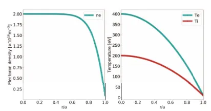
ne, the electron temperature,Te, and the ion temperature,
Tiof the background plasma are assumed to be:
ne=2.0−1.8×(r/a)8 [1019m−3],
Te=400−390×(r/a)2 [eV],
Ti=200−190×(r/a)2 [eV],
wherer/a is the normalized minor radius. The described profiles are presented in Fig. 1. We simulate the NBI heat-ing with 30000 test particles usheat-ing the HFREYA code and 10000 test particles using the GNET code, with the total beam power set to 1 MW.
In order to investigate the independence of the heat de-position on the injection angle of the neutral beam, param-eterφinjis introduced. φinjis defined by the toroidal angle
of the magnetic axis in Boozer coordinates. The neutral beam is injected from a relatively large port 6 of the HSX to pass point (ψ, θ, φ) = (0,0, φinj) in Boozer coordinates
as shown in Fig. 2. Theφinjvalue changes between 0.03π
and 0.28πrad, and the value in the perpendicular injection is 0.13πrad.
3. Simulation Results
We study the beam ion birth process by varying the in-jection angle,φinj, and the beam energy using the HFREYA
Fig. 1 Radial profiles of the electron density (left), and the elec-tron and ion temperatures (right).
Fig. 2 The definition of the injection angle,φinj.
Fig. 3 Plots of the beam ion birth rates as a function of the beam injection angle,φinj, with the four different beam injection
energy; 15, 20, 25 and 30 keV.
code. Figure 3 shows the beam ion birth rates as a function of φinj with four different injection energy values, where
the beam ion birth rate corresponds to the ratio of the number of ionized test particles to the initial neutral test particles (30000 particles). There is a minimum point of the beam ion birth rate near the perpendicular injection (φinj = 0.13π), and the beam birth rates vary from 30%
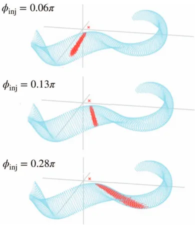
Fig. 4 Birth points of the beam ions with three different injection angles,φinj, from 0.13 - 0.28π.
particles have larger collision cross sections and are ion-ized more easily. The beam ion birth points with three dif-ferent injection angles are shown in Fig. 4. A longer beam path length can be observed when the injection angles are changed from 0.13πto 0.28π.
We define heat deposition rate as the ratio of the heat deposition to the total beam power (1 MW). Figure 5 shows (a) the total heat deposition rate (integrated over minor ra-diusρ(=r/a) 0 to 1) and (b) the core heat deposition (inte-grated overρ(=r/a) 0 to 1/2). These results indicate that the heat deposition rate is strongly dependent on the injec-tion angle and two peaks appear in the core heating. Heat deposition rate from 38% (30 keV) to 52% (15 keV) can be expected if the proper injection angle is set (approximately
φinj = 0.05πor 0.20π). Conversely, it is found that the
heat deposition rate becomes very small (−1%) near the perpendicular injection.
To elucidate the cause of the decline in the heat depo-sition seen in Fig. 5, we investigate the orbits of the in-jected beam ions and the rates of the trapped particles. Figure 6 shows the typical orbits of test particles (φinj =
0.08π, 0.13π, 0.22πrad). It can been seen that the beam ions have a complex orbit in the perpendicular injection case,φinj=0.13π. This complex orbit is a result of the
en-ergetic (large gyro-radius) trapped particle drift behavior with the non-helically symmetric magnetic components of the HSX. The rate of trapped particles is shown in Fig. 7. We find that about 80% of the beam ions are trapped in the perpendicular injection case,φinj = 0.13π. A large
frac-tion of the beam ions is therefore lost from the plasma core before the energy slow down in the perpendicular injection case.
Subsequently, we study the effects of charge exchange
Fig. 5 Heat deposition rates of the NBI heating integrated for the interval ofρ(= r/a) 0 to 1 (a), and the interval 0 to 1/2 (b).
Fig. 6 Typical orbits of injected beam ions (ρ is the starting point of the ion beams).
Fig. 7 Plot of the rate of trapped particles as a function of the beam injection angle.
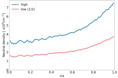
Fig. 8 Radial profiles of the neutral density carlculated using the AURORA code.
Fig. 9 Heat deposition rates of the NBI heating with the charge exchange loss.
(high pattern) and 5.0×109cm−3(low pattern). We
con-sider the QHS configuration of the HSX and the injection beam energy of 20 keV. Figure 9 shows the heat deposi-tion rates including the charge exchange loss. In the high neutral density case, the maximum value of the heat depo-sition rate is 15%, which is 70% lower than that with no charge exchange loss. In the low case, the maximum value is 25%. These results indicate that the charge exchange re-duces the heat deposition by 50 - 70% and that control of the neutral density is critical to increase the heat deposition
Fig. 10 Heat deposition rates in the QHS and Mirror configura-tions.
Fig. 11 NBI ion birth rates of the H-beam and the D-beam.
of the NBI heating in HSX.
Furthermore, We study the magnetic configuration ef-fect on the heat deposition of the NBI heating. The com-parison of the heat depositions in the Mirror and QHS con-figurations is shown in Fig. 10. No clear difference in the heat deposition rates between the QHS and Mirror config-urations can be seen. This is because the trapped beam ion motions are complex in both configurations and are lost by orbit loss before the slow down. This result indicates that the QHS configuration does not have an advantage in the confinement of trapped fast ions.
Fig. 12 Heat deposition rates of the NBI heating in the H-beam case and the D-beam case.
4. Summary
We have studied the NBI heating in the HSX using HFREYA and GNET simulation codes in order to find the optimum injection angle and beam energy. We have inves-tigated the heat deposition rate of the NBI by varying the injection angle of the neutral beam and the beam energy. The effects of charge exchange loss by the neutral particles on the heat deposition have also been studied.
It has been found that the heat deposition rate strongly depends on the injection angle, and the heat deposition rate of more than 50% can be expected if the proper injection angle is set. The heat deposition rate in the
perpendicu-lar injection case is, however, approximately 1%, This is due to the complex orbits of the trapped beam ions, which account for roughly 80% of total beam ion.
The heat deposition deteriorates significantly as a re-sult of the charge exchange loss. The maximum heat de-position rates are approximately 20% in the high neutral density case, and approximately 30% in the lower one. It is critical to control the neutral density in order to increase the heat deposition of the NBI heating in HSX.
We have compared the heat deposition rates between the QHS and Mirror configurations, as well as between beam ion species, hydrogen and deuterium. No clear dif-ference can be seen in the heat deposition rates between the QHS and Mirror configurations. The heat deposition rates in the deuterium beam case are smaller than those in the hydrogen beam case.
[1] A.F. Almagriet al., IEEE Trans. Plasma Sci.27, 114 (1999). [2] S.P. Gerhardtet al., Phy. Rev. Lett.94, 015002 (2005). [3] J.M. Caniket al., Phy. Rev. Lett.98, 085002 (2007). [4] J.N. Talmadgeet al., Plasma Fusion Res.3, S1002 (2008). [5] S. Murakamiet al., Fusion Technol.27, Suppl. S 256 (1995). [6] S. Murakamiet al., Nucl. Fusion40, 693 (2000).
[7] S. Murakamiet al., Nucl. Fusion46, S425 (2006).
[8] H. Yamaguchi and S. Murakami, Plasma Fusion Res. 9, 3403127 (2014).
[9] H. Yamaguchi and S. Murakami, Plasma Fusion Res. 11, 2403094 (2016).