In Pursuit of Excellence in Science
Vol. 7, No. 1, June 2013 • ISSN : 1823-6782
ASM
Science Journal
7(1) 2013
RESEARCH ARTICLES
New Formulated Hybrid Catalysts for the Synthesis of Carbon
Nanotubes via Chemical Vapour Deposition Technique 1 B. Nor Aziah and I. Fatiha
Liquefaction of Mukah Balingian Coal via Semi-continuous Two-stage
Solvent Flow Reactor System 7
M.A.M. Ishak, M.T. Safian, Z.A. Ghani and K. Ismail
Electron-phonon Coupling Constants of Two-dimensional Copper Oxide-based
High Temperature Superconductors 18
R. Abd-Shukor and W.Y. Lim
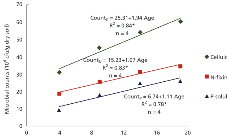
Cellulolytic, Nitrogen-fixing and Phosphate-solubilizing Micro-organisms as
Biological Indicators of Forest Soil Rehabilitation 23
A. Tang, S.K. Wong, O.H. Ahmed and N.M. Majid
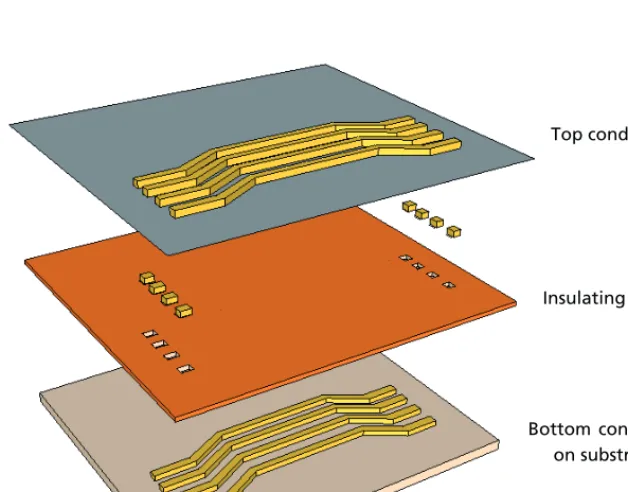
Investigations on Physical Characteristics of Three-dimensional
Coil Structure for MEMS Magnetometer 27
N. Sulaiman and B.Y. Majlis
A Study on the Effects of Environment on Curing Characteristics of Thixotropic
and Room Temperature Cured Epoxy-based Adhesives Using DMTA 37
Z. Ahmad, H. Rohana and P. Md Tahir
Towards Improved Construction Waste Management: A Review on the Issues, Challenges and the Need of the Supply Chain Management Mechanisms in
Residential Housing Development in Malaysia 59
M.N.N. Husna, R.M.R. Ahmad, R.E. Intan and C.H. Asmawati
Contents
ASM Sc. J. Volume 7(1), 2013
intro.indd 1
•
•
Price (2 Issues)
Malaysia: RM100 (Individual)
RM200 (Institution)
Other Countries: USD50 (Individual)
USD100 (Institution)
INTERNATIONAL ADVISORY BOARD
Ahmed Zewail (Nobel Laureate)
Richard R. Ernst (Nobel Laureate)
Lee Yuan Tseh (Nobel Laureate)
John Sheppard Mackenzie
M.S. Swaminathan
EDITORIAL BOARD
Editor-in-Chief/Chairman: Md. Ikram Mohd Said
Abdul Latiff Mohamad
Chia Swee Ping
Ibrahim Komoo
Lam Sai Kit
Lee Chnoong Kheng
Looi Lai Meng
Mashkuri Yaacob
Mazlan Othman
Mohd Ali Hashim
Francis Ng
Radin Umar Radin Sohadi
Cover:
The design of the cover was fashioned from two figures:
• The left of the cover, found on pp. 55 (Figure 17 — SEM micrographs) of an article entitled A Study on the Effects of Environment on Curing Characteristics of Thixotropic and Room Temperature Cured Epoxy-based Adhesives Using DMTA (pp. 37–58), where researchers from Universiti MARA and Universti Putra Malaysia investigated the thermal properties of epoxy-based adhesive reinforced with nano- and micro-particles before and after exposure to the different environmental conditions. The results showed that room temperature cured epoxies were only partially cured at room temperature.
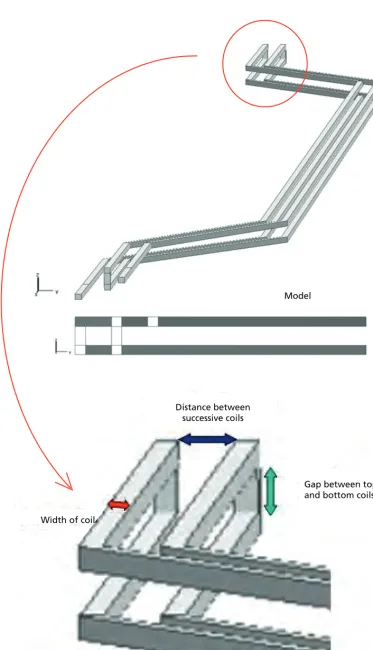
• On the right of the cover shows a three-dimensional coil structure (Figure 1, pp. 28) in the article entitled Investigations on Physical Characteristics of Three-dimensional Coil Structure for MEMS Magnetometer (pp. 27–36). Scientists at Universiti Kebangsaan Malaysia investigated (using FEM simulation) the physical characteristics of three-dimensional coils and its correlation with magnetic energy. The changing of the dimension size of the coil had an effect on inductance, magnetic energy and magnetic flux density.
In Pursuit of E xcellence in Scienc
e
Vol. 7, No. 1, June 2013 • ISSN : 1823-6782
© Academy of Sciences Malaysia
All rights reserved. No part of this publication may be reproduced in any form or by any means without permission in writing from the Academy of Sciences Malaysia.
The Editorial Board, in accepting contributions for publications, accepts no responsibility for the views expressed by authors.
ASM Science Journal is listed and indexed in Scopus. Published by the Academy of Sciences Malaysia
The Academy of Sciences
Malaysia (ASM)
The Academy of Sciences Malaysia (ASM) was established, under the Academy of Sciences Act 1994 which came into force on 1 February 1995, with the ultimate aim to pursue excellence in science. Thus the mission enshrined is to pursue, encourage and enhance excellence in the field of science, engineering and technology for the development of the nation and the benefit of mankind.
The functions of the Academy are as follows:
•
To promote and foster the development of science, engineering and technology•
To provide a forum for the interchange of ideasamong scientists, engineers and technologists
•
To promote national awareness, understanding andappreciation of the role of science, engineering and technology in human progress
•
To promote creativity among scientists, engineers and technologists•
To promote national self-reliance in the field of science, engineering and technology•
To act as a forum for maintaining awareness on thepart of the Government of the significance of the role of science, engineering and technology in the development process of the nation and for bringing national development needs to the attention of the scientists, engineers and technologists
•
To analyse particular national problems and identifywhere science, engineering and technology can contribute to their solution and accordingly to make recommendations to the Government
•
To keep in touch with developments in science, engineering and technology and identify those developments which are relevant to national needs to bring such developments to the attention of the Government•
To prepare reports, papers or other documents relating to the national science, engineering and technology policy and make the necessary recommendations to the Government•
To initiate and sponsor multi-disciplinary studiesrelated to and necessary for the better understanding of the social and economic implications of science, engineering and technology
•
To encourage research and development andeducation and training of the appropriate scientific, engineering and technical man power
•
To establish and maintain relations between theAcademy and overseas bodies having the same or almost similar objectives in science, engineering and technology as the Academy
•
To advise on matters related to science, engineering and technology as may be requested by the Government from time to time; and•
To carry out such other actions that are consistent withthe 1994 Academy of Sciences Act as may be required in order to facilitate the advancement of science, engineering and technology in Malaysia, and the well being and status of the Academy.
The Academy is governed by a Council. Various Working Committees and Task Forces are charged with developing strategies, plans and programmes in line with the Academy’s objectives and functions.
The functions of the Council are:
•
To formulate policy relating to the functions of theAcademy
•
To administer the affairs of the Academy•
To appoint such officers or servants of the Academy as are necessary for the due administration of the Academy•
To supervise and control its officers and servants•
To administer the Fund; and•
To convene general meetings of the Academy todecide on matters which under this Act are required to be decided by the Academy.
The Academy has Fellows and Honorary Fellows. The Fellows comprise Foundation Fellows and Elected Fellows. The Academy Fellows are selected from the ranks of eminent Malaysian scientists, engineers and technocrats in the fields of medical sciences, engineering sciences, biological sciences, mathematical and physical sciences, chemical sciences, information technology and science and technology development and industry.
The Future
Creativity and innovation are recognised the world over as the key measure of the competitiveness of a nation. Within the context of K-Economy and the framework of National Innovation System (NIS), ASM will continue to spearhead efforts that will take innovation and creativity to new heights in the fields of sciences, engineering and technology and work towards making Malaysia an intellectual force to be reckoned with.
intro.indd 1
RESEARCH ARTICLES
New Formulated Hybrid Catalysts for the Synthesis of Carbon
Nanotubes via Chemical Vapour Deposition Technique 1 B. Nor Aziah and I. Fatiha
Liquefaction of Mukah Balingian Coal via Semi-continuous Two-stage
Solvent Flow Reactor System 7
Electron-phonon Coupling Constants of Two-dimensional Copper Oxide-based
High Temperature Superconductors 18
R. Abd-Shukor and W.Y. Lim
Biological Indicators of Forest Soil Rehabilitation 23 A. Tang, S.K. Wong, O.H. Ahmed and N.M. Majid
Investigations on Physical Characteristics of Three-dimensional
Coil Structure for MEMS Magnetometer 27
N. Sulaiman and B.Y. Majlis
A Study on the Effects of Environment on Curing Characteristics of Thixotropic
and Room Temperature Cured Epoxy-based Adhesives Using DMTA 37 Z. Ahmad, H. Rohana and P. Md Tahir
Towards Improved Construction Waste Management: A Review on the Issues, Challenges and the Need of the Supply Chain Management Mechanisms in
Residential Housing Development in Malaysia 59 M.N.N. Husna, R.M.R. Ahmad, R.E. Intan and C.H. Asmawati
Contents
ASM Sc. J. Volume 7(1), 2013
C
M
Y
CM
MY
CY
CMY
K
NEWS FOCUS
Bio-Jet Fuel — Challenges and Solutions 67
P. Hauh and A. Kraft
Towards a Fully Functional Marine Mammal Stranding Response
Network in Malaysia 69
Cheryl Rita Kaur
COMMENTARY
Paleolithic Age (Tampanian) Stone Tool Production ‘Workshops’, Kota Tampan,
Perak — Was it Toba which Destroyed the Industry 70,000 Years Ago? 71
P. Loganathan
Climate Change — Environment and Infectious Diseases 74
C.P. Ramachandran
Instrumentation…‘Not Just Music’ 77
Q. M. Zaki
SCIENTIST IN PROFILE
Emeritus Prof Augustine S.H. Ong – bestowed Malaysia’s prestigious 2013
Merdeka Award for Health, Science and Technology 79
ANNOUNCEMENTS
WIF-KL 2013 81
Top Research Scientists Malaysia (TRSM) 82
Carbon nanotubes (CNTs) are tubular structures that are typically of nano-size diameter and many of micrometers in length. This fascinating one dimensional material has captured the attention of researchers worldwide with their extraordinary electronic and mechanical properties. These remarkable physicochemical properties have made them useful in various potential applications
such as hard composite tribological coating (Sing et al.
2009), gas storage media (Chambers et al. 1998), gas
sensors (Tibbetts 2001) and semiconducting materials
(Frackowiak & Beguin 2001). In order to fulfil the
demands for commercial applications, large quantities of CNTs at a low cost of production are required. There are numerous established methods which have been developed to produce CNTs, including laser ablation, arc discharge and catalytic chemical vapour deposition (CCVD). Among these three methods, CCVD is the most promising because it exhibit direct control on the reaction parameters such as the reaction temperature, reaction gase composition and
flow rate, reaction time and catalyst. In addition, CCVD
is also an economical means of producing CNTs in larger
scale (Ryu et al. 2008).
The size of the catalyst particle is controlled to the nanometer range with the development of the new
formulated hybrid catalysts. In this approach, two or more metals can either be bonded to each other in a metal oxide cluster or can be a mixture of two separate oxide phases in a metal cluster. For instance, it has been observed that catalysts made by the addition of molybdenum to iron stabilized the active iron nanoparticles (Lacerda 2004). Cui et al. (2008) also found the synergy of Mo and Fe-Ni alloy is the main reason for the high yield of CNTs. The most effective and common catalysts used for the growth of CNT by means of the CCVD are Fe, Co and Ni. Co-Mo catalysts show high selectivity and activity for the synthesis of single-walled carbon nanotube (SWCNT)
using ethanol as the gas precursor (Ni et al. 2006). The role
of catalyst in the CCVD method for producing CNTs is to enhance the decomposition of the carbon sources such as hydrocarbon compounds, carbon monoxide and carbon dioxide by means of the pyrolysis process (Anne-Claire 2005). The introduction of lanthanide metals, ions or oxides to the formulated catalyst will contribute to the generation of interesting properties such as supports, promoters or additives (Sakata 1999).
There are three types of hybrid catalyst formulated in this work which consist of Ni, Mn, Cr doped with Nd, respectively. Investigations on the catalytic activity
New Formulated Hybrid Catalysts for the
Synthesis of Carbon Nanotubes via Chemical
Vapour Deposition Technique
B. Nor Aziah1* and I. Fatiha1
Transition metals play an important role in the growth of carbon nanotubes (CNTs). Series of unsupported hybrid catalysts consisting of Ni:Cu, Ni:Cr, and Ni:Mn doped with Nd catalyst, respectively were synthesized by impregnation method. The catalytic performance of the catalyst for the production of CNTs was measured in the pyrolysis process of hydrocarbon source by catalytic chemical vapour deposition method. Acetylene gas was used as the source of carbon in the pyrolysis process. The decomposition of acetylene was carried out at 700ºC. The bulk properties of the catalysts were investigated by X-ray diffraction. Field emission scanning electron microscopy and thermal analysis were used to observe the morphology and thermal stability of the as-synthesized CNTs, respectively. Hybrid catalyst of Ni:Mn/Nd and Ni:Cr/Nd in 3:1 atomic ratio gave high percentage of carbon yield which was assigned for the high production of CNTs with the mass of yield 18 times greater than the initial mass of the catalyst used.
Key words: Carbon nanotubes; chemical vapour deposition; Lanthanide; acetylene; pyrolysis; impregnation method; chemical vapour deposition; X-ray diffraction; morphology; thermal stability
ASM Sci. J., 7(1), 1–6
1Department of Chemistry, Faculty of Science, Universiti Teknologi Malaysia, 81310 Johor Bahru, Johor, Malaysia
ASM Science Journal, Volume 7(1), 2013
2
performance of the hybrid catalysts for the synthesis of
CNTs were carried out using a fixed-bed chemical vapour
deposition reactor. The physical and chemical properties of the hybrid catalysts were then characterized using
X-ray diffraction (XRD), field emission scanning electron
microscope (FESEM) and thermogravimetric analyser (TGA).
MATERIALS AND METHODS
Preparation of the Catalysts
Series of hybrid catalysts of Ni:Cu, Ni:Cr and Ni:Mn doped with Pr with the atomic ratio of 3:1:0.3 were prepared from a mixture of nickel (II) nitrate hexahydrate
Ni(NO3)2.6H2O, copper nitrate [Cu(NO3)2], manganese
(II) acetate [(CH3COO)2Mn.4H2O], chromium (III)
nitrate (Cr(NO3)3.6H2O) and praseodymium (III) nitrate
[Pr(NO3)3.6H2O], respectively. Optimum quantities of the
respected metal salts were dispersed in a sufficient amount
of water and mixed well to get a homogeneous mixture of the salt solution. The mixture was dried at 80ºC for 24 h and calcined at 700ºC for 5 h. The catalyst mixture was
then cooled and finely ground into fine powder of hybrid
catalyst.
Synthesis of Carbon Nanotubes
The synthesis was carried out using a horizontal
fixed-bed CCVD reactor in atmospheric pressure. The reactor consisted of a tube furnace with a quartz tube where the decomposition of the acetylene gas took place (Figure 1). About of 200 mg of catalyst was placed at the centre (hot zone) of the tube furnace. Nitrogen as the carrier gas was simultaneously introduced into the reactor tube
at the flow rate of 0.3 l/min. The mixed gases were then flown over the catalyst to allow the decomposition of the
carbon precursors to occur. The reaction was left for 30 min at 700ºC. The reaction chamber was then cooled to room temperature. The yield in the form of black powder was collected and the percent of carbon composition was determined from Equation 1:
Carbon yield (%) = M1 (1)
M2
Where, M1 is the mass of carbon deposited after the reaction
and M2 is the mass of catalyst used.
CHARACTERIZATION
The Hybrid Catalysts
The identification of metallic bulk crystallographic and
amorphous phase in the hybrid catalysts were carried
out by XRD. The analysis of the hybrid catalyst by XRD were conducted using Diffractometer D500 Siemens
Crystalloflex with CuKα (λ = 1.54060 Ǻ) as the radiation
source.
The As-synthesized CNTs
The as-synthesized CNTs were characterized by the
JSM-6701F field emission scanning electron microscope
(FESEM) to determine the morphology of the CNTs. The thermal stability and purity of the CNT was analysed using the Mettler Toledo TGA.
RESULTS AND DISCUSSION
X-ray Diffraction
The type of metal oxide in the hybrid catalysts formulation
is one of the factors that influence the catalytic activity
and morphology of the deposited carbon (Chai et al.
2007; Nyamori et al. 2008). XRD patterns of the hybrid
catalysts were shown in Figure 2. From the diffratogram pattern, it shows that the active oxide phase, NiO present in Ni:Cr/Nd and Ni:Mn/Nd catalysts. While in Ni:Cu/Nd catalysts, Ni species tends to form the binary oxides of Ni19CuO20 with high peaks intensity. It was identified in
this work that the presence of NiO phase had contributed to the high production of CNTs with the mass of yield 18 times greater than the initial mass of the Ni:Cr/Nd and Ni:Mn/Nd catalysts used respectively, but not for Ni:Cu/ Nd catalyst.
In comparison to the respective diffractograms pattern of the hybrid catalysts, it was observed that Ni:Cr/Nd was in the amorphous form, while the hybrid Ni:Mn/Nd and Ni:Cu/ Nd catalysts represented the polycrystallite form. This new formulated hybrid catalysts of the respected Ni:Mn/Nd and Ni:Cu/Nd had generated two types of crystallite structures.
Firstly, the spinal oxide of NiMn2O4 which was observed
in the hybrid Ni:Mn/Nd catalyst formulation, constructed
from NiO and Mn2O3 phases and served as the active site
for the excellent catalytic performance in the production of
CNTs. Secondly, the ternary oxide of Nd4(CuNi)O8 which
was present in the Ni:Cu/Nd catalyst and constructed from
metal ions of various oxidation states of Ni2+, Cu2+ and
Nd3+ in the perovskite type of oxide. The ternary oxide
in the hybrid catalyst of Ni:Cu/Nd existed as Ni19CuO20
phase, instead of Ni20O20 (or NiO phase). The molecular
formula of the perovskite oxide showed that one mole of the Ni site in the NiO lattice cluster was probably replaced
by one mole of Cu2+ ion, and resulted in the reduction of the
catalytic performance of the NiO phase in the formulated Ni:Cu/Nd hybrid catalyst.
From the catalytic measurement of the Ni based hybrid catalysts, results obtained revealed that the incorporation
B. Nor Aziah and I. Fatiha: New Formulated Hybrid Catalysts for the Synthesis of Carbon Nanotubes
of the Cr, Mn and Cu, in the hybrid catalyst formulations affected the catalytic performance of the respected catalyst. It also proved that Ni was acting as the active species while Cr was acting as the dispersant to hinder the aggregation of Ni particle, so as to control the particle size of the catalyst, and it was in agreement with the work done by Chen and Wu (2005). The agglomeration and aggregation process among the Ni particles were further hindered by the addition of small amounts of Nd as the dopant, hence, it stabilized the size of the particles of catalyst in the nanometer range. In addition, with the assistance of the respected Mn and Cr in the Ni based hybrid catalysts formulation, the reduced environment during the synthesis was sustained. Thus, it contributed towards the controlled production of the
specific form of CNTs.
CHARACTERIZATION OF THE AS-SYNTHESIZED CARBON NANOTUBES
Micrograph of FESEM
FESEM micrographs in Figure 3 confirmed the morphology
of all carbon nanomaterials obtained by the decomposition of acetylene at 700ºC over Ni:Cr/Nd, Ni:Mn/Nd and Ni:Cu/Nd hybrid catalysts are the CNTs. This proved that each of the hybrid catalysts were able to produce CNTs but they differed in term of the quality. The diameter of CNTs obtained was within the range of 10 nm to 50 nm. The smaller diameter CNTs plays an important role,
specifically in the gas storage application and bio-sensors
(Philippe 2009), and as for the larger diameter CNTs the applications was more to the fabrication of advanced composite materials.
The Ni:Mn/Nd catalyst gave the highest density of CNTs, whereas the Ni:Cr/Nd catalyst exhibited better quality CNTs. The Ni:Mn/Nd and Ni:Cu/Nd hybrid catalysts gave non-uniform CNTs with the mixture of different forms of carbon nanomaterials (Figure 3b and 3c). The small diameter CNTs was observed when using Ni:Cr/ Nd (Figure 3a) due to the presence of small sized particles of catalyst which were assigned earlier as amorphous in the XRD analysis.
The presence of spinal NiMn2O4 compound in the
Ni:Mn/Nd hybrid catalyst formulation gave the highest density of production of as-synthesized CNTs. The common active species, NiO had catalyzed the growth of CNTs in Ni:Mn/Nd and Ni:Cr/Nd hybrid catalysts. The combination of Ni:Cu/Nd hybrid catalyst resulted in the
formation of ternary oxide of Nd4(CuNi)O8. This ternary
compound had initiated the formation of the mixture of carbon nanomaterials with the large diameter of 50 nm
(Figure 3c). The presence of the specific oxide phases in the hybrid catalysts identified from the XRD analysis had
clearly explained its contribution towards the morphology of the as-synthesized CNTs observed from the FESEM.
From the micrographs of the FESEM, it was noted that the growth mechanism of MWCNT followed the based growth model, indicated by the absence of white spots at
the tips of the CNTs floss (Anne-Claire 2005).
Lin (Cps) 0 1 2 3 4 5 6 7 8 9 10 11 12 13 14 15 16 17 18 19 20 21 22 23 24 25 26 27 28 29 (b) (a) (c) NiO
Ni19CuO20
CuO Nd4(CuNi)O8
NiO NiMn2O4
Nd2O2(O2)
NdCr(O3) Cr2O3
Micro-reactor Tube furnace Catalyst Gas trap Fume hood Acetylene gas Nitrogen gas
20 30 40 50
2-Theta - Scale
60 70 80 90
N2 regulator Mixing chamber Acetylene regulator Acetylene flow meter
N2 flow
meter
ASM Science Journal, Volume 7(1), 2013
4 Thermal Gravimetric Analysis
Thermal gravimetric analysis (TGA) is one of the fundamental studies to differentiate the types of carbon nanomaterials. Its purity can be determined by calculating the percentage of mass loss during the heat treatment. The decomposition temperatures in Table 1 shows that the CNTs synthesized using the respected Ni:Cr/Nd, Ni:Mn/ Nd and Ni:Cu/Nd hybrid catalysts gave one region of mass loss. This was an indication for the complete combustion of
the specific form of CNTs with high purity, produced from
the respected hybrid catalyst formulated.
It was found that, CNTs synthesized using Ni:Cr/ Nd catalyst had the lowest decomposition temperature at 500°C with 90.64% of mass loss, which indicated that the diameter of the as-synthesized CNTs was the smallest compared to the other two hybrid catalysts formulated (Table 1). Small diameter CNTs usually decomposed at lower temperature compared to that of the larger diameter
CNTs (Li et al. 2009). This result was in good agreement
with the FESEM analysis of CNTs showed in Figure 2a. Whereas, the decomposition temperature for the as-synthesized CNTs from Ni:Mn/Nd catalyst occurred at the highest temperature of 630°C with 96.98% of mass loss. This observation as attributed to the presence of larger
diameter CNTs and the presence of other form of carbon nanomaterials and was in agreement with the FESEM analysis showed in Figure 2b. The as-synthesized CNTs
dominated was identified as MWCNTs and depicted high
quality and purity when using Ni:Cr/Nd. However, when using Ni:Cu/Nd and Ni:Mn/Nd the CNTs produced were highly dense.
CONCLUSION
Series of new hybrid catalysts of Ni:Mn/Nd, Ni:Cr/Nd and Ni:Cu/Nd, have been successfully formulated for the production of MWCNTs with the average diameter of 30
nm. The presence of the oxide phases, identified as spinal
and ternary oxides in the hybrid catalyst formulation, were the active phases which had enhanced the growth of CNTs. The metal-metal interactions in the catalyst had strongly
influenced the growth of the CNTs, specifically with high
purity and density. The Cr, Mn and Cu transition metals introduced in the Ni based hybrid catalysts formulation were acting as the promoter towards the formation of the active oxide phases as well as the dispersant to enhance the production of CNTs; whereas, the addition of Nd had enhanced the formation of nanoparticle catalyst with uniform size.
Lin (Cps)
0 1 2 3 4 5 6 7 8 9 10 11 12 13 14 15 16 17 18 19 20 21 22 23 24 25 26 27 28 29
(b) (a)
(c) NiO
Ni19CuO20
CuO Nd4(CuNi)O8
NiO NiMn2O4
Nd2O2(O2)
NdCr(O3)
Cr2O3
Micro-reactor
Tube furnace
Catalyst
Gas trap Fume hood
Acetylene gas Nitrogen
gas
20 30 40 50
2-Theta - Scale
60 70 80 90
N2
regulator
Mixing chamber
Acetylene regulator
Acetylene flow meter
N2 flow meter
Figure 2. XRD patterns for series of hybrid catalysts: (a) Ni:Cr/Nd, (b) Ni:Mn/Nd and (c) Ni:Cu/Nd catalysts.
B. Nor Aziah and I. Fatiha: New Formulated Hybrid Catalysts for the Synthesis of Carbon Nanotubes
Figure 3. FESEM micrographs of as-synthesized CNTs over series of hybrid catalysts: (a) Ni:Cr/Nd; (b) Ni:Mn/Nd and (c) Ni:Cu/Nd.
(c)
(a) (b)
Table 1. Percentage of mass loss of as-synthesized CNTs from TGA.
Samples Temperature of decomposition (ºC) Purity of CNTs (%)
Ni:Mn/Nd 630ºC 96.98
3:1
Ni:Cr/Nd 3:1 500ºC 90.64
3:1
Ni:Cu/Nd 3:1 550ºC 46.22
ASM Science Journal, Volume 7(1), 2013
6 ACKNOWLEDGEMENT
We would like to express our gratitude to the Ministry of Higher Education (MOHE) for the Fundamental Research Grant Scheme (FRGS) 78543, the Ministry of Science, Technology and Innovation of Malaysia for the National Science Fellowship, and Universiti Teknologi Malaysia (UTM) for the support.
Date of submission: May 2011 Date of acceptance: September 2012
REFERENCES
Anne-Claire, D 2005, 'The catalyst in the CCVD of carbon nanotubes-a review', Progress in Materials Science, vol. 50, pp. 929–961.
Chai, SP, Zein, SHS & Mohamed, AR 2007, 'Synthesizing carbon nanotubes and carbon nanofibers over supported-nickel oxide catalysts via catalytic decomposition of methane', Diamond & Related Materials, vol. 16, pp. 1656–1664.
Chambers, A, Park, C, Baker, RTK & Rodriguez, NM 1998, 'Hydrogen storage in graphite nanofibers', J. Phys. Chem.
B., vol. 102, pp. 4253–6.
Chen, B & Wu, P 2005, 'Aligned carbon nanotubes by catalytic decomposition of C2H2 over Ni-Cr Alloy', Carbon, vol. 43, pp. 3172–3177.
Cui, Y, Wu, X, Wu, H, Tian, Y & Chen, Y 2008, 'Optimization of synthesis condition for carbon nanotubes by chemical vapor deposition on Fe-Ni-Mo/MgO catalyst', Materials
Letter, vol. 62, pp. 3878–3880.
Frackowiak, E & Beguin, F 2001, 'Carbon materials for the electrochemical storage of energy in capacitors', Carbon, vol. 39, pp. 937–50.
Lacerda, RG, Teh, AS, Yang, MH, Teo, KBK, Rupesinghe, NL, Dalal, SH, Koziol, KKK, Roy, D, Amaratunga, GAJ, Milne, WI, Chhowalla, M, Hasko, DG, Wyczisk, F & Legagneux,
P 2004, 'Growth of high-quality single-wall carbon nanotubes without amorphous carbon formation', Appl.
Phys. Lett., vol. 84. pp. 269.
Li, N, Wang, X, Ren, F, Haller, GL, Pfefferle, LD 2009, 'Diameter tuning of single-walled carbon nanotubes with reaction temperature using a co monometallic catalyst', Journal of
Physical Chemistry C, vol. 113, no. 23, pp. 10070–10078.
Ni, L, Kuroda, K, Zhou, LP, Kizuka T, Ohta K, Matsuishi K & Nakamura, J 2006, 'Kinetic study of carbon nanotube synthesis over Mo/Co/MgO catalysts', Carbon, vol. 44, pp. 2265–2272.
Nyamori, VO, Mhlanga, SD, Coville, NJ 2008, 'The use of organometallic transition metal complexes in the synthesis of shaped carbon nanomaterials', Journal of
Organometallic Chemistry, vol. 693, pp. 2205–2222.
Philippe, R, Caussat, B, Falqui, A, Kihn, Y, Kalck, P, Bordere, S, Plee, D, Gaillard, P, Bernard, D & Serp, P 2009, 'An original growth mode of MWCNTs on alumina supported iron catalysts', Journal of Catalysis, vol. 263, pp. 345–358.
Ryu, H, Singh, BK & Bartwal, KS 2008, 'Synthesis and Optimization of MWCNTs on Co-Ni/MgO by Thermal CVD H', Advances in Condensed Matter Physics, Article ID 971457, 1–6.
Sakata, Y, Nobukini, S, Kikumoto, E, Tanaka, K, Imamura, H & Tsuchiya, S 1999, 'Preparation and catalytic property of a copper-lanthanide oxide binary system for hydrogenation reaction', Journal of Molecular Catalysis
A: Chemical, vol. 141, pp. 269–276.
Singh, V, Diaz, R, Balani, K, Agarwak, A & Seal, S 2009, 'Chromium carbide CNT composites with enhanced mechanical properties', Acta Mater., vol. 57, pp. 335–44.
Tibbetts, GG, Meisner, GP & Olk, CH 2001, 'Hydrogen storage capacity of carbon nanotubes, filaments, and vapor-grown fibers', Carbon, vol. 39, pp. 2291–2301.
Wang, H & Moore, JJ 2012, 'Low temperature growth mechanisms of vertically aligned carbon nanofibers and nanotubes by radio frequency-plasma enhanced chemical vapor deposition', Carbon, vol. 50, pp. 1235–1242.
With the increase in world energy demand and the depletion of petroleum crude oil, efforts have been made by researchers to seek alternative new sources of energy. Renewable energy such as solar and biomass have a high potential to cater for energy; however, with the extensive world coal reserves, proper attention needs to be considered to further upgrade and fully utilize this priceless fuel. Hence, with this in mind, studies of coal liquefaction to produce an alternative liquid fuel, as one of the upgrading coal processes, have been increasing in recent years. Intense efforts have been made to liquefy coal, with the processes such as pyrolysis, solvent extraction and
catalytic hydrogenation using either batch or solvent flow
reactor system have achieved some degree of success. In some countries, coal is used as a consumption material to generate steam for production of electrical power. Both
gasification and liquefaction of coal produce gaseous and
liquid fuels that can be easily transported (e.g. by pipeline) and conveniently stored in tanks. In the transportation and industrial sector, more than 80% of the energy consumed is provided by fossil fuel energy such as coal, petroleum and natural gas which are the main energy resources worldwide (Anon 2002).
Solvent flow reactor system has been used by many
researchers for its ability to investigate the coal liquefaction process rather at high temperatures. One important aspect
in the solvent flow reactor system is the enabling of the
removal, quenching and characterization of extracts release from the coal prior to the onset of the product degradation
reactions (Begon et al. 2002). In addition, the ability to
introduce fresh solvent throughout the liquefaction process
will be beneficial in yielding high coal conversion. Given that the extracts will flow out to be collected, the solvent flow reactor can be manipulated by installing additional reactor to it. In this study, the second reactor filled with
catalyst was installed, in order to increase the oil yield conversion. Depending on the coal rank and condition, the coal liquefaction processes are routinely being carried out at temperatures near or above 400ºC at which the coal will be actively decomposed and the process is often written as:
Coal• + H• = (Pre-asphaltenes + asphaltenes + oils) + H2O + gas
The role and the importance of catalyst in coal liquefaction are well known. The addition of active
Liquefaction of Mukah Balingian Coal via
Semi-continuous Two-stage Solvent Flow Reactor System
M.A.M. Ishak1*, M.T. Safian1, Z.A. Ghani1 and K. Ismail1
Solvent flow reactor system was introduced into the extraction system to increase the system efficiency
and enhance the extraction yield by adding fresh solvent during the extraction processes. The liquefaction
experiment was carried out at various flow-rates (1, 3 and 5 ml/min), reaction times (30, 45 and 60 min) and reaction temperatures (300ºC, 350ºC, 400ºC, 420ºC and 450ºC) with tetralin as solvent. Despite the ability of adding fresh solvent into the extraction process, the conversion of oil+gas was still considered to be low as there was ~25% of coal extracts left to be converted into low molecular weight compounds. One possible
option to increase the oil yield is by applying catalyst that will further break up the coal extracts into small
molecular weight compounds. In this study, a second reactor was introduced consisting of catalyst (NiSiO2)
assuming that the catalyst would interact more effectively with coal extracts rather than the coal itself. In the
absence of catalyst, the oil yield was 55%. By introducing the Ni catalyst, the oil yield increased by 15%. Further analysis of GCMS showed that the oil from catalytic liquefaction gave out more low molecular weight compounds in comparison to the un-catalytic liquefaction oil.
Key words:Coal; liquefaction; solvent-flow; GCMS; Ni catalyst; oil conversion; molecular weight compounds; asphaltene; pre-asphaltene; tetralin
ASM Sci. J., 7(1), 7–17
1Fuel Combustion Research Laboratory, Faculty of Applied Sciences, Universiti Teknologi MARA, 02600 Arau, Perlis, Malaysia
ASM Science Journal, Volume 7(1), 2013
8
catalysts improves total conversion and selectivity which will increase the yield of oils. This results in more
efficient hydrogen consumption. Furthermore, the catalysts
used will affect the reduction of reaction such as lower
temperature, pressure and reaction time. Prasassarakich et al. (2007) studied that in the absence of catalyst, the oil
yield decreased with temperatures above 410ºC and the
content of naptha and kerosene increased while light gas oil and gas oil decreased with increasing temperatures. The use of an appropriate catalyst due to more severe thermolysis of the coal structure, results in an increase in the amount of the coal structure; thus, an increase in the amount of lighter and intermediate compounds at the expense of the higher molecular weight compounds.
Liquefaction of Mukah Balingian (MB) low-rank coal was carried out using semi-continuous solvent flow
two-stage reactor system at temperatures above 400ºC in order to study the effect of catalytic liquefaction by separating the coal and the catalyst in different reactors. Both extraction and radical reactions occurred as shown by the
increase in the percentages of asphaltenes, pre-asphaltenes and oil+gas yield (Kassim et al. 2007). The second reactor
filled with catalyst needed to break those asphaltenes and pre-asphaltenes. This solution will increase the oil+gas
yield. In this paper, the results obtained from this process such as oil conversion and distribution of asphaltene and preasphaltene at several parameters were discussed.
EXPERIMENTAL
Sample Preparation
The coal sample used in this study is MB Malaysian low-rank coal which originated in Sarawak, Malaysia.
The procedure for coal preparation has been reported by
Ishak et. al. (2005). Briefly, the coal samples were ground
and sieved through progressively into finer screen to obtain particle sizes of <212 μm, and dried in the oven for overnight to remove the inherent moisture. Table 1
represents the ultimate, proximate and maceral analyses
of the MB coal sample. All the solvents and reagents used
in this study were obtained from commercial sources and
were used without further purification.
The catalyst was prepared using wet-impregnation technique (Venugopal et al. 2007). The support material used is fumed silica supplied by Aldrich Chemical and
nickel nitrate (Ni(NO3)2.6H2O) which is the precursor for
the nickel. Briefly, the required amount of nickel nitrate is taken to give Ni loading catalyst of 5wt% with known amount of water in a 1000 ml beaker and mixed with the
requisite amount of SiO2 to yield the respective Ni mass
percentages (i.e. 1, 3, 5 w/w%). The solution was dried and constantly stirred at 100ºC, then the process of drying
was continued for another 24 h. The dried sample was
calcinated in air at 700ºC for 5 h.
Coal Liquefaction
The liquefaction experiments were carried out in two stainless steel tubing (40 ml and 20 ml). A schematic
diagram for the semi-continuous two-stage reactor system is shown in Figure 1. For each experiment, 5 g
of coal sample was loaded into the 40 ml tubing reactor.
The second tubing reactor was filled with 5 g of catalyst.
Nitrogen gas was charged into both reactors to remove any air left in the reactor. The solvent was pumped into the
reactors first with the exit closed, to permit the build-up
of the desired pressure and temperature. The heater was turned on to reach the desired temperature at the heating
rate of 4ºC/min. The reactor pressure was controlled by a back-pressure regulator valve to maintain a 4 MPa of
pressure. Upon reaching the desire temperature, the solvent
was pumped in at varied flow-rates.
The coal extracts were collected at various temperatures and various reaction times. At the end of each experiment, the furnace was withdrawn and the reactors were cooled down to room temperature. The coal residue was recovered
by filtration and dried overnight in vacuum oven at 100ºC. The weight loss of the coal sample after extraction on dry-ash-free (daf) basis defined the degree of coal conversion.
The extracted product collected was then separated into
oil (soluble), asphaltene (toluene-soluble, hexane-insoluble) and pre-asphaltene (THF-soluble, toluene-insoluble) using a soxhlet extraction method. The
hexane-soluble was put in a rotary evaporator under vacuum to remove the solvent and the oil obtained was analyzed using
GCMS. The coal conversion and liquid yield were calculated using following expressions (Gozmen et al. 2002):
Coal conversion:
[wt. % daf] = Wcoal (1 – αo) – Wresidue (1 – α) /
Wcoal (1 – αo) 3 100 (1)
Product yields:
[wt. % daf] = Wi / Wcoal (1 – αo) 3 100 (2)
where, Wcoal, Wresidue and Wi were the weight of parent
coal, residue coal and each constituent of extracts (i.e.
asphaltenes, pre-asphaltenes and oil+gas); and αo and α
were ash content in parent coal and ash content in coal liquefaction residue, respectively. In this study no attempt was made to recover the tetralin in order not to remove
some other volatile products as well; however, the oil+gas
yield values were calculated by difference.
Extracts and Residue Analysis
The soxhlet extraction method was used to separate the coal
extracts into oils, asphaltene, and pre-asphaltene. Hexane,
tolune and THF were used separately as solvents in this
M.A.M. Ishak et al.: Liquefaction of MB Coal via Semi-continuous Two-stage Solvent Flow Reactor System
extraction method. The coal mixtures contained in the 1000 ml round-bottom flask was heated until a colourless solvent
was observed in the soxhlet extractor (i.e. about 4 h). The
hexane-soluble was then cooled down before the n-hexane
was evaporated by using the rotary evaporator. Toluene was used to replace the hexane and the extraction was
continued on the hexane-insoluble in the soxhlet extractor
and the same procedure was applied in the extraction using THF. Figure 2 shows the schematic diagram of soxhlet extraction method.
The coal liquid was analyzed by Gas Chromatography Mass Spectroscopy (Varian Model CP-3800) according to ASTM D2887. The column used is CP8944, 30 m 3 0.25
mm 3 0.39 mm packed with VF-5ms. The oven temperature was raised from 60ºC to 270ºC at a constant heating of 5ºC/
min. The separated compounds will immediately enter the mass spectrometer which generates the mass spectrum for the compounds. The carrier gas used was helium through
a flow rate of 20 ml/min and the analysis was run in split mode at 30:70. The raw and the coal liquefaction residue were analyzed for proximate analysis using DTA/DSC TA Model SDT Q600 that follows the ASTM D2974. Carbon, hydrogen and nitrogen analyses were performed using an
Elemental Analyzer (EA), model CHNS-932 series, with
helium gas as the carrier and followed the ASTM D3172 for
the ultimate analysis.
RESULTS AND DISCUSSION
Liquefaction Using Solvent-flow Reactor System
Effect of reaction temperature. Effects of the reaction
temperature on the liquefaction of MB coal are represented in Table 2 and Figure 3. During this experiment, other parameters such as solvent flow-rate and reaction time were fixed at 1 ml/min and 30 min, respectively. It is equally
important to determine the appropriate temperature for the liquefaction in order to enhance the coal conversion and oil
yield. Figure 3 shows that the coal conversion increased
with increasing temperature. It was also noted that the
increased reaction temperature also increased the oil+gas yield. At low temperature (300ºC), the coal conversion was at the lowest and increased significantly until it reached
420ºC where the conversion began to linear up.
According to Karaca et al. (2001), the bond cleavage reactions in lignite and pre-asphaltene occurred simultaneously beyond 350ºC. Thus, it was possible that
Table 1. Characteristics of Mukah Balingian coal sample.
Proximate analysis (wt% db) Ultimate analysis (wt% daf) value (MJ/kg)Calorific
Volatile Fixed Ash C H N S O
matter carbon content
Raw coal 44.7 51.1 4.2 63.9 5.1 1.9 0.5 28.6 24.6
(daf = dry-ash-free basis, db = dry basis)
Table 2. Effect of various extraction conditions for coal liquefaction on the conversion of product yields.
Exp FR (ml/min) Extraction conditions RT (min) Temp. (ºC) Total Conversion (% daf)PAS AS O+G
Effect of solvent flow-rate
1 1 30 420 78.9 12.4 11.9 54.7
2 3 30 420 78.1 12.0 16.5 49.7
3 5 30 420 78.4 11.4 17.3 48.6
Effect of reaction time
4 1 30 420 77.9 12.4 11.9 54.7
5 1 45 420 78.7 11.6 8.8 58.3
6 1 60 420 79.4 11.9 7.3 60.1
Effect of reaction temperature
7 1 30 300 41.2 15.1 12.4 13.7
8 1 30 350 59.5 15.6 13.5 30.4
9 1 30 400 73.1 7.6 11.7 53.8
10 1 30 420 78.9 11.8 12.3 54.6
11 1 30 450 79.2 11.3 13.1 54.8
N2
Valve
Preheater
Controller
Pressure gauge
Pressure outlet
1st reactor coal bed
2nd reactor catalyst bed Back pressure
regulator
Condenser Sample
collected
Condenser
Coal liquefaction liquid
Extraction with hexane
Oil (Hexane-soluble)
Asphaltene (Toluene-soluble)
Pre-asphaltene (THF-soluble)
Hexane-insoluble
Extraction with toluene
Toluene-insoluble
Extraction with THF
Toluene-insoluble Solvent
HPLC pump N2
Valve
Preheater
Controller
Pressure gauge
Pressure outlet
1st reactor coal bed
2nd reactor catalyst bed Back pressure
regulator
Condenser Sample
collected
Condenser
Coal liquefaction liquid
Extraction with hexane
Oil (Hexane-soluble)
Asphaltene (Toluene-soluble)
Pre-asphaltene (THF-soluble)
Hexane-insoluble
Extraction with toluene
Toluene-insoluble
Extraction with THF
Toluene-insoluble Solvent
HPLC pump
Figure 1. Schematic diagram of semi-continuous two-stage solvent flow reactor system.
Figure 2. A schematic diagram of soxtlet extraction.
90
80
70
60
Total Oil+gas PAS AS
50
40
Conversion (% daf) 30
20
10
0
300 350 400
Temperature (ºC)
420 450
90
80
70
60
Total Oil+gas PAS AS 50
40
Conversion (% daf) 30
20
10
0
30 45
Reaction time (min)
60 90
80
70
60
Total Oil+gas PAS AS
50
40
Conversion (% daf) 30
20
10
0
300 350 400
Temperature (ºC)
420 450
90
80
70
60
Total Oil+gas PAS AS 50
40
Conversion (% daf) 30
20
10
0
30 45
Reaction time (min)
60 Figure 3. Effect of reaction temperature on product distribution yields (Nitrogen pressure — 4 MPa. See Table 2 for the other nomenclature).
ASM Science Journal, Volume 7(1), 2013
12 during that temperature, all pre-asphaltene and asphaltene
were converted into lighter molecular components of
oil+gas. Therefore, it was definitive that the coal extraction tended to pre-dominate at lower liquefaction temperature,
with radical reaction which started to occur at liquefaction
temperature at or above 400ºC. According to Prasassarakich et al. (2007), increasing the temperature above 410ºC will
cause a decrease in liquid yield. This was because when using high reaction temperature, the liquid was fragmented and formed free radicals and was stabilized by hydrogen to form the gas phase. However, further increasing of the temperature would result in more gas formation and less oil. Hence, it was suggested that 420ºC was the optimum temperature which resulted the high coal conversion and oil yield.
Effect of reaction time. The effect of reaction time on
coal conversion and product yields of MB coal was also
investigated and the results are shown in Figure 4 and Table 2. Apparently, the percentages of coal conversion at each different reaction time were relatively the same. There
was a slight difference in the oil+gas yield as the reaction
time increased. The data indicated that the reaction time affected only a little in enhancing the total conversion.
A fair amount of coal conversion and oil+gas yield were
observed with the lesser amount of reaction time which also could be improve by the introduction of catalyst in the liquefaction process. The less reaction time also meant less solvent used which is economical compared to the amount of solvent used with a longer reaction time.
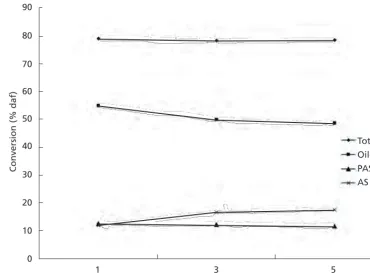
Effect of solvent flow-rate. Another significant
para-meter that could improve in the development of coal
liquefaction process is solvent flow-rate. In an attempt to achieve high coal conversion and oil+gas yield, it is
important to ensure that enough fresh solvent is present during the extraction process. One option is by providing solvent into the reactor continuously during the liquefaction
process. The effects of solvent flow-rate are shown in Figure 5 and Table 2. Generally, the coal conversions for three different flow-rates were relatively the same. The
percentage of asphaltene increased while the percentage of
pre-asphaltene was found to decrease with the increasing of solvent flow-rate.
These results indicated that by enabling the solvent to
flow during liquefaction process, it was possible to extract
more components out of the coal with high percentage of
coal conversion (~80%) regardless of the different
flow-rate of the solvent used. Furthermore, the presence of
fresh hydrogen-donor solvent during the reaction process
stabilized most of reactive radical species to form low
molecular weight products such as asphaltene and pre-asphaltene, and also the light products of oil+gas. In other word, with a sufficient supply of fresh donor solvent during coal liquefaction, most of the asphaltene and pre-asphaltene were converted into oil+gas.
Similar results for the amount of solvent on coal
conversion were reported by Simsek et al. (2001), where
the extent of conversion of coal depends on how the radicals are being stabilized. Thus, the liquefaction yield would be
high if there was sufficient hydrogen available, while the liquefaction yields would be low if there was insufficient
availability of hydrogen which would cause the radicals to
undergo re-polymerisation. The liquefaction performed with a high solvent flow-rate produced a low percentage of oil yield and a high percentage of asphaltene+pre-asphaltene.
This might be due to the extraction during liquefaction which only dissolved, due to the less time, for the solvent to fully interact with the coal radical. In other words, less hydrogen was transferred during the liquefaction process, thus resulting in higher molecular weight compounds,
which in this case is asphaltene and pre-asphaltene. Hence,
more extensive formation of extractable materials was
obtained at a lower solvent flow-rate.
Liquefaction Using Two-stage Solvent Flow Reactor System
The two-stage reactor was introduced to increase the percentage of oil yield. The second reactor was filled with
NiSiO2 as the liquid tar passed through after the extraction
process in the first reactor. In order to maintain the condition
for both reactors, several parameters in the second reactor
such as temperature, pressure and solvent flow-rate were fixed at 420ºC, 4 MPa and 1 ml/min, respectively. The
effects of Ni loading on the product distribution yields
are shown in Figure 6. From Figure 6, it was clear that the oil+gas yield increased as the percentage of Ni loading increased. Higher molecular weight compounds such as
pre-asphaltene and pre-asphaltene decreased and were converted
into lower molecular weights compound, that is, oil+gas.
The second reactor did not affect the total conversion, thus, there was no difference in the total conversion of the catalyst.
Liquefaction was also conducted isothermally for a
specific duration of time. Using the two-stage reactor system, the percentage of asphaltene and pre-asphaltene decreased and this correlated with the increased oil+gas yield. The assumption was that both asphaltene and pre-asphaltene have been converted into oil+gas. Generally, with the sufficient amount of hydrogen available, these free
radical species generated from the coal cracking process combined with hydrogen to yield stable species such as
asphaltene, asphaltene and oil. The asphaltene and
pre-asphaltene would further fragment to smaller molecular weight radical species, and then the hydrogenation process
stabilized it to form oil+gas, a light molecular weight
product.
The use of catalyst also increased the oil+gas yield.
Both the hydrogenation reaction and hydrocracking of coal molecule occurred with the availability of catalyst.
90
80
70
60
Total Oil+gas PAS AS 50
40
Conversion (% daf) 30
20
10
0
1 3
Solvent flow-rate (ml/min)
5
90
80
70
60
Total Oil+gas PAS AS 50
40
Conversion (% daf) 30
20
10
0
1 3
Ni loading (wt%)
5 7
90
80
70
60
Total Oil+gas PAS AS 50
40
Conversion (% daf) 30
20
10
0
1 3
Solvent flow-rate (ml/min)
5
90
80
70
60
Total Oil+gas PAS AS 50
40
Conversion (% daf) 30
20
10
0
1 3
Ni loading (wt%)
5 7
Figure 5. Effect of solvent flow-rate on product distribution yields.
ASM Science Journal, Volume 7(1), 2013
14
Another reason was that the low rank coals with their high concentrations of oxygen functional group adsorbed
the multi-charged metal cation through an ion exchange
mechanism and this property is used for dispersing metal catalysts across a coal surface prior to extraction (Hu
et al. 1998). The catalyst itself improves the reactivity of
liquefaction by weakening the dependence of conversion on molecular hydrogen and hydrogen donor solvent (Hu
et al. 2000). Thus, it would be beneficial in decreasing the
hydrogen consumption during liquefaction and increasing the conversion of coal liquefaction.
Coal Liquid Analysis by GCMS
The aim of this section is to compare the chromatography
spectra for the catalytic and un-catalytic coal liquefaction
liquid. Theoretically, the reducing catalyst used would further reduce the coal extracts including coal liquid into smaller molecular compounds. By observing the difference in the chromatography spectra between those two coal liquids, the reducing effect of catalyst could be proved. Figures 7 and 8 show the results of coal liquid extract from coal liquefaction at a temperature of 420ºC without and
with catalyst by using GCMS, respectively.
For MB coal extraction, the existence of a complicated mixture and that of many compounds were identified. MB coal is a low rank coal having high carboxyl and/
or sulphidic type functional groups and based on the previous study, the covalent breakage starts at temperatures
between 400ºC to 425ºC (Begon et al. 2002). According
to Prasassarakich et al. (2007), during coal liquefaction the main reactions were thermolysis, dehydrogenation,
cleaving of cyclic hydrocarbon structures into an open-chain hydrocarbon and condensation reactions. Moreover, Prasassarakich et al. (2007) found that the improvement in coal liquefaction can be achieved by adding catalyst into the coal. Furthermore, he concluded that in the absence of a catalyst, the oil yield decreased and the content of naphtha and kerosene increased while the light gas oil and
gas decreased. The presence of catalyst would benefit the
formation of lighter components, kerosene and light gas oil.
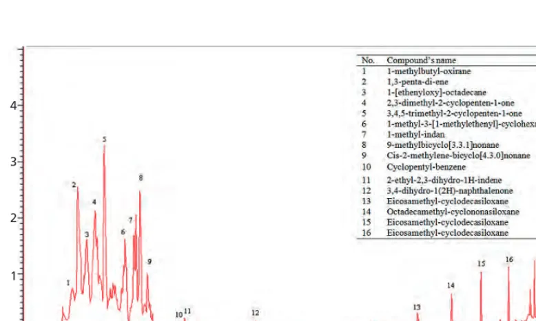
From Figure 8, it can also be seen that there is a collection of compounds that appeared at the beginning of retention time. It showed that there are differences in compounds between these two chromatography spectra (Figure 7) which indicated that the catalyst did play its part in further reducing the molecular compounds in
coal extracts. The major compounds that were identified
(by mass spectrometer’s library) in coal liquid extraction
for non-catalytic liquefaction were mostly alcohols and
aromatic hydrocarbons. Benzene and naphthalene are two
popular compounds in coal. Yagmur et al. (2008) found
that most of the components in coal consist of condensed aromatic and oxygenous aromatic compounds during their study on liquefaction of Zonguldak bituminous coal using tetralin as solvent.
Furthermore, several aromatic compounds were found to decrease in intensity when the chromatography was
compared for catalytic and non-catalytic coal extracts. Compounds such as 1-methyl-indan, 2-ethyl-2,3-dihydro-1H-indene, and 3,4-dihydro-1(2H)-naphthalenone have high intensity in non-catalytic coal extracts but low in Table 3. Conversion, PAS yield, AS yield and O+G yield.
Ni Loading Extraction conditions Conversion (% daf)
(wt%) FR (ml/min) RT (min) Temp. (ºC) Total PAS AS O+G
Effect of Ni loading (two-stage solvent flow reactor)
1 1 30 420 78.1 10.3 7.4 60.4
3 1 30 420 78.2 8.1 4.4 65.7
5 1 30 420 77.9 5.5 2.9 69.5
7 1 30 420 78.9 5.3 3.8 69.8
Table 4. Proximate and ultimate analyses of raw and CLR of MB coal.
Sample Proximate (wt% db) Analyses Ultimate (wt% db) value (MJ/Kg)Calorific
VM FC Ash C H N Oa S
Raw 44.7 51.1 4.2 63.9 5.1 1.9 28.6 0.5 24.6
CLR 27.9 65.0 7.1 73.7 4.1 2.5 19.6 0.1 27.6
VM = volatile matter; FC = fixed carbon; a = calculated by difference.
4
3
2
1
0
10 20
Minutes
30 40
4
3
2
1
0
10 20
Minutes
30 40
4
3
2
1
0
10 20
Minutes
30 40
4
3
2
1
0
10 20
Minutes
30 40
Figure 7. Chromatography of coal liquid extract from coal liquefaction without catalyst.
ASM Science Journal, Volume 7(1), 2013
16
catalytic coal extracts. These correspond to the catalyst reaction in forming more lighter aliphatic components in coal liquefaction. Thus, by enabling the availability of catalyst, there would be more formation of lighter components.
Proximate and Ultimate Analyses of Coal Residue
In order to analyze the properties of coal before and after liquefaction, proximate and ultimate analyses were carried out on the coal liquefaction residue (CLR). The proximate
and ultimate analyses of CLR of MB coal are shown in Table 4, with raw MB coal results for comparison. All
liquefaction processes were carried out at the best condition
(temperature of 420ºC; processing time of 30 min; solvent flow-rate of 1 ml min–1; and pressure of 4 MPa).
From Table 4, it can be seen that the volatile matter of the CLR decreased when compared to the raw coal
from 44.7 wt% to 27.9 wt%. However, the fixed carbon content for the CLR increased from 51.1 wt% to 65.0 wt% due to the releasing of volatile matter that
occurred during liquefaction. In addition, an increase
in value for the ash content was observed, i.e. from 24.6 MJ/kg to 27.6 MJ/kg.
The decrease of volatile matter corresponds to the
increased fixed carbon and ash content which resulted in
the increase of the heating value of the CLR. The increased value in the ash content of the CLR was due to the removal of organic matter from the coal liquefaction with mineral which is inorganic materials being concentrated in the
coal residue (Ishak et al. 2005). From the results thus far,
it showed that the coal underwent an upgrading process
producing a CLR with higher calorific value. Thus, these
results indicated that the CLR would be a good feedstock
for gasification and/or combustion in coal upgrading
processes as indicated by Sangon et al. (2006), Hu et al.
(1998) and Williams (1981).
CONCLUSION
Liquefaction on MB coal was successfully carried out at
three different variable parameters: temperature; reaction
time; and solvent flow-rate. The first phase was liquefaction using an ordinary one-stage solvent reactor system
which produced high coal conversion but there was 24% of the total conversion converted into high molecular
weight compounds (asphaltene and pre-asphaltene). The
second phase of this study was liquefaction using the
two-stage solvent flow reactor system which consisted
of NiSiO2 as catalyst in the second reactor. It was found
that an increase of 15% was achieved in the oil+gas yield from the conversion of asphaltene and pre-asphaltene. This showed that the use of catalyst could increase the oil+gas
yield.
ACKNOWLEDGEMENTS
The authors would like to thank the Ministry of Science, Technology and Innovation, Malaysia (MOSTI) for the e-Science research grant (No: 03-01-01-SF0017) and Universiti Teknologi MARA.
Date of submission: October 2011 Date of acceptance: October 2012
REFERENCES
Anon 2002, 'The energy picture, in The new book of popular
science, vol. 2, Glolier educational.
Begon, V, Suelves, I, Li, W, Lazaro, MJ, Herod, AA & Kandiyoti, R 2002, 'Catalytic hydrocracking of primary maceral concentrate extracts prepared in a flowing solvent reactor’, Fuel, vol. 81, pp. 185–202.
Gozmen, B, Artok, L, Erbatur, G & Erbatur, O 2002, 'Direct liquefaction of high-sulfur coals: effects of the catalyst, the solvent and the mneral matter', Energy & Fuels, vol. 16, pp. 1040–1047.
Hu, H, Sha, G & Chen, G 2000, 'Effect of solvent swelling on liquefaction of Xinglong coal at less severe conditions', Fuel Processing Technology, vol. 68, pp. 33–43.
Hu, H, Guo, S & Hedden, K 1998, 'Extraction of lignite with water in sub and supercritical states', Fuel Processing
Technology, vol. 53, pp. 269–277.
Ishak, MAM, Ismail, K, Abdullah, MF, Kadir, MOA, Mohamed, AR & Abdullah, WH 2005, 'Liquefaction studies of low rank Malaysian coal using high-pressure high-temperature batch wise reactor system', Coal Preparation Journal, vol. 25, pp. 221–237.
Karaca, H, Ceylan, K & Olcay, A 2001, 'Catalytic dissolution of two turkish lignites in tetralin under nitrogen atmosphere: effect of the extraction parameters on the conversion', Fuel, vol. 80, pp. 559–564.
Kasim, NN, Ismail, K, Ishak, MAM & Abdullah, MF 2007, 'The effect of microwave pre-treatment on Mukah Balingian low-rank coal towards product distribution during liquefaction process', in Proceeding International
Conference on Coal Science and Technology.
Prasassarakich, P, Methakhup, S & Ngamprasertsith, S 2007, 'Improvement of oil yield and its distribution from coal extraction using sulfide catalysts', Fuel, vol. 86, pp. 2485– 2490.
Sangon, S, Ratanavaraha, S, Ngamprasertsith, S & Prasas-sarakich, P 2006, 'Coal liquefaction using supercritical toluene-tetralin mixture in a semi-continuous reactor',
Fuel Processing Technology, vol. 87, pp. 201–207.
Simsek, EH, Karaduman, A & Olcay, A 2001, 'Liquefaction of Turkish coals in tetralin with microwaves', Fuel Processing
Technology, vol. 73, pp. 111–125.
Venugopal, V, Naveen, SK, Ashok, J, Prasad, DH, Kumari, VD & Prasad, KBS 2007, 'Hydrogen production by
M.A.M. Ishak et al.: Liquefaction of MB Coal via Semi-continuous Two-stage Solvent Flow Reactor System
catalytic decomposition of methane over Ni/SiO2', International Journal of Hydrogen Energy, vol. 32,
pp.1782–1788.
Yagmur, EHSE, Aktas, Z & Togrul, T 2008, 'Effect of CuO receptor on the liquid yield and composition of oils
derived from liquefaction of coals by microwave energy',
Energy Conversion and Management, vol. 49, pp. 3043–
3050.
Williams, DF 1981, 'Extraction with supercritical gases',
18
The understanding of the mechanism of superconductivity in the cuprates has been one of the major challenges in condensed matter physics since the discovery of this class of superconductors many years ago. Several models have been proposed throughout the years. Basically there are
two opposing views on the possible mechanism. The first
idea is based on the electron-phonon interaction and the other is based on the one-band Hubbard Hamiltonian. The electron-phonon interaction in the cuprates is said to be too
weak to produce a high Tc. On the other hand, it is not easy to
explain the thermodynamic properties of the cuprates with positive potential of the Hubbard model. A combination of
both ideas to explain high Tc superconductivity has been
reported recently (Szczesniak et al. 2012).
Although the possible role of phonons in the cuprates has been abandoned earlier on, the important role of phonons in the pairing mechanism in the materials has regained attention in the past few years following a number
of experimental and theoretical evidences (Lanzara et al.
2001; Reznik et al. 2006; Shimada et al. 2002). By taking
into consideration the singularity in the density of states at the Fermi level for a two-dimensional system, recent works have shown that such a model can be viable for high
temperature superconductivity (Newns et al. 1995).
A large effect can be produced near the van Hove singularity even for arbitrarily weak interactions
(Vozmediano et al. 2002). Hence in principle, a very small
electron-phonon coupling is sufficient for the formation of
the Cooper pairs. It is interesting to determine the value of the electron-phonon coupling constant in the cuprate. In a previous paper we reported the electron-phonon coupling constant in the cuprates for the van Hove scenario (Abd-Shukor 2007). In this paper we calculated the electron-phonon coupling constant for the van Hove scenario derived from three expression of the transition temperature (Getino
et al. 1993; Newns et al. 1992; Tsuei et al. 1990) and by using parameters determined from acoustic methods. The electron-phonon coupling constants were then compared to experimental results of direct measurements of the electron-phonon coupling constant.
Models
The density of states at the Fermi level in the van Hove scenario is given as:
, (1)
Electron-phonon Coupling Constants of
Two-dimensional Copper Oxide-based
High Temperature Superconductors
R. Abd-Shukor1* and W.Y. Lim1
The electron-phonon coupling constant of the copper oxide-based high temperature superconductors in the van Hove scenario was calculated using three known models and by employing various acoustic data. Three expressions for the transition temperature from the models were used to calculate the constants. All three models assumed a logarithmic singularity in the density of states near the Fermi surface. The calculated electron-phonon coupling constant ranged from 0.06 to 0.28. The constants increased with the transition temperature indicating a strong correlation between electron-phonon coupling and superconductivity in these materials. These values were smaller than the values estimated for the conventional three-dimensional BCS theory. The results were compared with previous reports on direct measurements of electron-phonon coupling constants in the copper oxide based superconductors.
Key words: Acoustic methods; electron-phonon coupling constant; van Hove scenario; transition temperature models
ASM Sci. J., 7(1), 18–22
1School of Applied Physics, Faculty of Science and Technology, Universiti Kebangsaan Malaysia, 43600 Bangi, Selangor, Malaysia
*Corresponding author (e-mail: [email protected])
N E
( )
= Noln EFE EF
tanh E EF
2kBTc =
E EF
2kBTc
tanh E EF
2kBTc = 1
Tc =1.36(10 D)exp 2
NoV+ ln
kB(10 D) kB D
2 1 1 2 1 2
VH1 = NoV =
2
ln Tc 13.6 D
2
+1 ln 10
( )
22
V=
dE
E EF
(
)
2+ 2
T
( )
EF DEF+ D
N E
( )
tanh(
E EF)
2
+ 2
T
( )
2kBTc
Tc =1
2TFexp 1
N0V+D
D
2Tc,
TF
2Tc 2 coth
D
2TF +ln
2 TF D
VH 2 =N0V= ln2 2Tc
TF ln
2 10
( )
2 coth D 2Tc DD
2Tc,
TF
2Tc
1
Tc=
=
1.36TFexp 2+ln2 D
E 1
1 2
E*
[
fVe/ Ze]
2
D
VH 3=2 ln 2 Tc
13.6 D ln
2 D
E* +1
1
Tc=2.72TFe
1
TF=EF
kB