Adaptive TDMA Scheduling for Real-Time Flows in
Cluster-Based Wireless Sensor Networks
Gohar Ali1, Kyong Hoon Kim2, and Ki-Il Kim*2
1
Sur University College,Oman 2
Department of Informatics
Research Center for Aerospace Parts Technology Gyeongsang National University
Jinju-Dearo 501, Korea, 52828 *[email protected]
Abstract. To prevent scalability problem caused by increasing traffic of real-time applications, cluster architecture with Time Division Multiple Access (TDMA) schedul-ing scheme is mostly deployed in wireless sensor networks. However, even though it have proven good scalability and suitability for real-time communications, but static scheduling lacks of adaptability in several situations by not admitting some real-time flows where slots remain available.To solve mentioned problem, in this paper, we propose an adaptive cluster-based scheduling scheme for real-time flows by utilizing the time slots for flows according to type of flows such as inside or outside cluster. So, the proposed scheme can achieve better utilization of channel by minimizing the number of unused channels for real-time flows than static scheme
through new adaptive TDMA scheduling scheme. Simulation results show that more
flows are admitted and delivered within the deadline in the proposed scheme by uti-lizing unused time slots accordingly.
Keywords:real-time, , cluster, TDMA, scheduling, wireless sensor networks.
1.
Introduction
Real-time communication in Wireless Sensor Networks (WSNs) is increasing day by day due to their significant importance in a wide range of applications. Example applications include health monitoring, disaster management, seismic monitoring, fire monitoring sys-tem, industrial process monitoring and control. In all these systems, sensed data have to reach the monitoring station within specific time period or before the expiration of dead-line [19, 3, 5, 14, 10].
they are suitable for real-time communications [15, 1]. Among diverse contention-free MAC approaches, many research works have focus on TDMA method.
Until now, TDMA scheduling for real-time communication have been well studied in [16, 9, 2]. In WirelessHART network [16], real-time packets are scheduled using TDMA. Since this scheduling algorithm allows only one transmission in a time slot by not pro-viding spatial reuse, it limits the scalability of such approach. On the other hand, TDMA scheduling algorithm in [9] is proposed to allocate time slots based on requests and dead-line of nodes. This scheduling works where the nodes are one hop away from the des-tination. However, in some situations, all nodes cannot transmit directly to base station. Furthermore, since the mentioned schemes not only have scalability problem but also sup-port one-hop scheduling, this weakness leads to our new cluster-based TDMA scheduling algorithm in [2]. More detailed, our proposed scheduling algorithm divides intra-cluster time slots into two separate slots: IntraSend and IntraRecv. Real-time flows generated from a cluster are guaranteed to use IntraSend time slots, while those aiming at destina-tion at the cluster are scheduled in IntraRecv time slots. But, due to the static slot allo-cation, the intra-cluster scheduling algorithms cannot utilized available empty slots. So, some flows cannot be delivered within the deadline due to static allocation.
In order to solve mentioned problem by extending the our previous work, in this paper, we propose adaptive TDMA scheduling algorithm under a cluster architecture. In the proposed scheme, if the clusters that have either IntraSend or IntraRecv flows, they do not distinguish IntraSend and IntraRecv scheduling. It implies that flows in a cluster can make use of two time slots together. But, in the previous scheme, these time slots cannot be occupied by flows due to static allocation. That is, an adaptive scheduling scheme can utilize the intra-cluster time slots according to the states of the flows dynamically. Finally, simulation results show that proposed schemes have higher number of flows admitted and delivered within the deadline than the previous work.
The rest of the paper is organized as follows. Related work is described in the section 2. the system model and notation is introduced in the section 3. In the section 4, we ex-plain the proposed scheduling framework with example. Section 5 provides performance evaluation and section 6 concludes the paper.
2.
Related Work
short-est path algorithm with the help of combination between CHs and member nodes. In the point of CH selection, the authors [12] addressed a novel selection algorithm to maxi-mize the lifetime for motion detection. But, the real-time communication issues were not mentioned in this paper. Another cluster-based TDMA scheme to accomplish optimized energy efficiency and minimum delay was proposed in [17]. This scheme reduced the end-to-end latency by using the slot reuse concept. In [7], cluster-based unique converge-cast scheduling problem of information gathering was investigated. All nodes in a cluster has exactly one packet of information to be sent to the sink. They proposed heuristic al-gorithm based on spanning tree where the degree of transmission parallelism is increased by scheduling independent sets in the same slot.
In our previous work [2], real-time flows were scheduled by using TDMA time slots under cluster architecture. The time slots were divided into three different slots namely IntraSend, InterComm and IntraRecv slots. In IntraSend slots, real-time flows were sched-uled from source nodes to its CHs. In InterComm time slots, real-time flows from source CHs were scheduled to the destination CHs. Finally, in IntraRecv time slots, flows from destination CHs were transmitted to the destination nodes. Compared to other approaches, our scheme performs flow scheduling with the priority of flows where the inter-cluster communication consists of CHs that are less-resource constraints. However, due to static scheduling, intra-cluster scheduling cannot utilize empty slots adaptively.
3.
System Model and Notations
3.1. Network and Flow Model
The network is represented by a graphG = (V, E)whereV is the set of sensor nodes
andEdenotes the edges between nodes. These edges are represented bye= (u, v). We
assume that if there is edge between two nodes then they can communicate with each
other. Thus, communication edge−uv→indicates that nodeucan send data to nodev.
When nodes communicate each other, two types interference such as primary and/or secondary interference, may occur [18]. A primary interference occurs when a node re-ceives and transmits at the same time or rere-ceives more than one transmission destined to it. On the other hand, secondary interference occurs when an intended receiver of a par-ticular transmission is also within the transmission of another transmission intended for other nodes.
As for real-time communication, a real-time flow denoted byFi, is a set of message
streams from a source nodesrci to a destination nodedsti. Each flowFi has unique
priorityiso that flowFihas higher priority thanFj fori < j. For the frame structure,
global TDMA time slots are divided into three different time slots namely IntraSend, InterComm and IntraRecv slots as shown in Figure 1. By using IntraSend slots, member nodes send real-time packets to their CHs. While a CH transmits flows to the destination CH in InterComm slots, the flows from destination CH are transmitted to destination node in IntraRecv slots .
3.2. Assumptions
Fig. 1.Minor frame
(1) The nodes are randomly deployed and belong to one CH that is already known. (2) All nodes should send neighboring as well as flow information (flow id,
source-destination pair, deadline) to its CH at the initial phase and CHs sends results of IntraSend scheduling as well as information of neighboring CHs to one centralized point. The centralized point is already known to CHs at the deployment phase. (3) A centralized point runs proposed scheduling algorithm and distributes time slots to
all CHs.
(4) The routing path of nodes denoted by ϕwhich is computed by centralized point
through the shortest path algorithm. Any change in the flow information should be notified to CH as well as centralized point in order to trigger new allocation.
(5) Signal of CH is strong as much as possible to communicate with other neighbor CHs. (6) There is no link between member nodes located in different clusters.
(7) There is no interference among different clusters.
(8) If two nodes are within predetermined distance, then they can communicate and interference with each other.
(9) The flows are established in case that both source and destination belong to different clusters.
3.3. Notations
The TDMA frame number is represented byf rameminor while the number of slots in
a frame is denoted byNminor. In each frame, NIS,NIC,NIR denotes the number of
time slots for IntraSend(IS, InterComm(IC) and IntraRecv(IR) scheduling, respectively.
In IntraSend scheduling for flow Fi, the arrival time to the source CH is denoted by
aSH
i while the arrival time to the destination CH is represented byaDHi in InterComm
scheduling. Finally, arrival time to destination nodes of the flowFi is defined byai in
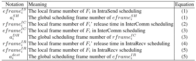
IntraRecv scheduling. The notation and equation number to include each variable are shown in Table 1.
4.
The Proposed Real-Time Flow Scheduling
4.1. Procedure
Table 1.Notations
Notation Meaning Equation
ef rameIS
i The local frame number ofFiin IntraSend scheduling (1) aSH
i The global scheduling frame number ofef rameSHi (1) rf rameICi The local frame number ofFi’ release time in InterComm scheduling (2) ef rameICi The local frame number ofFiin InterComm scheduling (3)
aDH
i The global scheduling frame number ofrf rameICi (3) rf rameIR
i The local frame number ofFi’ release time in IntraRecv scheduling (4) ef rameIRi The local frame number ofFiin IntraRecv scheduling (5) adesti The global scheduling frame number ofef rameIRi (5)
Fig. 2.An example of cluster-based real time flows
For example, in Figure 2 for initialization of IntraSend algorithm,F1 andF2 share
flow number and their interference with CHH1. Similarly, for IntraRecv algorithm,F2
andF3 share their flow number as well as interference with CHH3. Through the
ini-tialization of InterComm algorithm, each CH shares their results with centralized point. Next, in the scheduling part, IntraSend algorithm is used to schedule the flows from source nodes to their CHs while flows from one cluster to other clusters are scheduled by Inter-Comm algorithm. Finally, the flows from the CH to destination node is scheduled by the IntraRecv algorithm.
Flow# IntraSend InterComm IntraRecv ri 1 aiSH 2 3 aiDH 4 ai
F1 0 a b 1 b H1 4
F2 0 c z 4
F3 0 l H5 1 H5 H2 H2 H3 3 H3 g 4
F4 0
(a)
Flow# IntraSend InterComm IntraRecv
ri 5 aiSH 6 7 aiDH 8 ai
F1 4 H1 H3 H3 H2 7 H2 p 8
F2 4 z H1 5
F3
F4 4 m H5 5 H5 H2 6
(b)
Flow# IntraSend InterComm IntraRecv ri 9 aiSH 10 11 aiDH 12 ai
F1 8 p q 9
F2 H1 H3 10 H3 O 12
F3
F4 H2 H4 11 H4 d 12
(c)
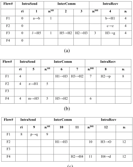
Fig. 3.Example of Proposed Adaptive scheduling
the IntraSend scheduling of the cluster uses bothNIS andNIRtime slots. Similarly, if a
cluster has only IntraRecv flows, the IntraRecv scheduling of the cluster uses bothNIS
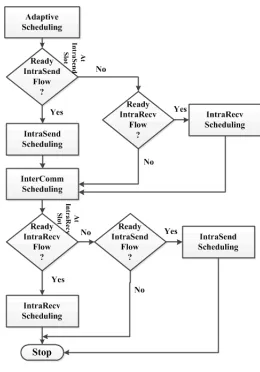
andNIRtime slots (e.g. H3 in Figure 2). The flowchart of adaptive scheduling is shown in
Figure 4. In addition, We also propose another adaptive scheduling scheme where clusters that have both IntraSend and IntraRecv flows can utilized each other slots. The details of adaptive scheduling are discussed in the following subsections.
4.2. Proposed Adaptive Scheduling
The sequence of adaptive scheduling algorithm is shown in Figure 4. As shown in for intra-cluster scheduling result, IntraSend and IntraRecv scheduling are performed if their flows are ready. On the other hand, if there is no ready flow in IntraSend frame, then IntraRecv flows are scheduled instead. In the same approach, IntraSend flows are scheduled if IntraRecv flows are not ready in corresponding frame.
Fig. 4.Proposed Scheduling Flowchart
4.3. Example and Algorithm of Proposed Adaptive Scheduling
We explain the proposed scheduling with an example for four real-time flows in Figure 2. These flows are scheduled in a sequence of IntraSend, InterComm and IntraRecv
schedul-ing at each frame through proposed adaptive scheduler as shown in Figure 4. TheNIS,
NIC,NIRis set to1,2, and1, respectively.
IntraSend Scheduling The pseudo-code of IntraSend scheduling is described in
Algo-rithm 1. The flows are scheduled in the cluster forNISslots(line5). Each CH manages
the IntraSend scheduling result by calling the function IA-FP-Scheduling 4(line10).
Af-ter scheduling, then expected arrival time of flows that is required to reach their CHs are
computed from the result of IntraSend scheduling(line13).
As an example in Figure 3(a), according to intraSend scheduling ofC1,F1are
sched-uled first thenF2is next turn. As transmission−→abofF1is interferencing with transmission
−
→czofF2, so transmission−→czis blocked because the priority ofF2is lower thanF1.
Algorithm 1IntraSend Scheduling(GC,F, NIS)
/∗GC= (VC, EC): the graph of clusterC∗/ 1: foreach clusterCido
2: foreach flowFi∈ Fdo
3: Fk←Fiby using the CH fordstk 4: ϕk←a path fromsrcito the CH inϕi 5: forkfrom 1 to|ϕk|andk≤NISdo 6: −uv→←thek-th edge inϕi
7: endfor
8: FC← FC∪(ri, Fk,−uv→) 9: endfor
10: TISC ←IA-FP-Scheduling(GC,FC)
11: endfor
12: foreach flowFido 13: CalculaterSH
i from the result ofTISC
14: endfor 15: returnTISC
−−−→
mH5is blocked according to priority. So, only F3 can be reached its CH. And, its
ar-rival time to source CH is calculated from result of IntraSend scheduling by equation
(1) whereef rameISi is the frame number of last transmission ofFi in the IntraSend
scheduling. The CH schedules each flows into the local scheduling table starting from
zero. Thus, ef rameISi is the local scheduling frame number of Fi resulting from
In-traSend scheduling so that the arrival time to cluster head in the global frame should be calculated. Equation (1) converts the local scheduling frame number into the arrival frame number in global scheduling table.
aSHi = $
eframeISi
NIS
%
×Nminor+eframeISi modNIS+ 1 (1)
InterComm Scheduling In this scheduling, the flows that arrive to the source CH are
transmitted to the destination CH. For this purpose, we build a sub-graphGheader
con-sisting of only CHs. The InterComm scheduling is used to allocateNIC slots and its
scheduling result is shared among CHs. As shown in Algorithm 2, the routing path
con-tains only the sub-path from source CH to destination CH(line5). Each flow is scheduled
forNIC slots(line6). The function IA-FP-scheduling 4 is used to adjust flows for
In-terComm scheduling(line11). After scheduling, the expected arrival time of flows is
obtained from the result of InterComm scheduling(line13). In InterComm scheduling,
this arrival frame number,aSH
i , is again converted into the local scheduling frame of the
InterComm scheduling node in order to schedule the flow after arrival at the CH, which is derived by Equation (2).
rframeICi =
j aSH
i
Nminor
k
×NIC ifaSHi 6=∅.
NIC×f rameminor ifaSHi =∅.
By this approach, onlyF3is arrived at CH at time 1. So, both−−−−→H5H2and−−−−→H2H3can be scheduled at frame 1 in InterComm scheduling as shown in Figure 3(a). The arrival time to the destination CH of flow is determined by Equation (3). Similar to Equation (2),
aDH
i andadesti in Equation (3) and (5) correspond to the global frame number at which
flowFiis delivered in the destination cluster and the destination node, respectively.
Algorithm 2InterComm Scheduling(Gheader,F, NIC) /∗Gheader: the graph consisting of only CHs∗/
1: foreach flowFi∈ Fdo 2: Fk←Fi
3: srck←the source CH ofFi 4: dstk←the destination CH ofFi 5: ϕk←a path fromsrcktodstkinϕi 6: forkfrom 1 to|ϕk|andk≤NICdo 7: −uv→←thek-th edge inϕi
8: endfor
9: FC ← FC∪ {(rframeiIC, Fk,−uv→)}
10: endfor
11: TIC←IA-FP-Scheduling(Gheader,FC)
12: foreach flowFido
13: CalculaterDHi from the result ofTIC 14: endfor
15: returnTIC
aDHi =
$
eframeICi
NIC
%
×Nminor+eframeICi modNIC+NIS+ 1 (3)
IntraRecv Scheduling In IntraRecv scheduling, the flows arrived at the destination CH are transmitted to destination node. Like IntraSend scheduling, each cluster manages the IntraRecv scheduling result through the pseudo-code shown in Algorithm 3. The
schedul-ing is done by callschedul-ing the function IA-FP-schedulschedul-ing 4 (line 11). Similar to previous
example, the release time slots of IntraRecv scheduling flows can be derived from the
arrival time ofFiat destination CH by Equation (4).
rframeIRi =
j aDH
i
Nminor
k
×NIR ifaDHi 6=∅.
NIR×f rameminor ifaDHi =∅.
(4)
Interestingly, in Figure 3(a) for clusterC1, no IntraRecv flows are ready to be
sched-uled. So, IntraSend transmission−−→bH1of F1 and−→czofF2are scheduled in IntraRecv slots.
Since onlyF3 is ready for IntraRecv scheduling in clusterC3, its transmission−−→H3g is
Algorithm 3IntraRecv Scheduling(GC,F, NIR)
/∗GC= (VC, EC): the graph of clusterC∗/ 1: foreach clusterCido
2: FC←∅
3: foreach flowFi∈ Fdo
4: Fk←Fiby using the CH forsrck 5: ϕk←a path from the CH todstiinϕi 6: forkfrom 1 to|ϕk|andk≤NIRdo 7: −uv→←thek-th edge inϕi
8: endfor
9: FC← FC∪ {(rf rameiIR, Fk,−uv→)} 10: endfor
11: TIRC ←IA-FP-Scheduling(GC,FC)
12: foreach flowFido
13: Calculateriaifrom the result ofTIRC
14: endfor 15: returnTIRC
adesti = $
eframeIRi
NIR
%
×Nminor +eframeIRi modNIR+NIS+NIC+ 1 (5)
In the nextf rameminor, the flows are scheduled as shown in the following Figure
3(b). Finally, in Figure 3(c), inC2, since there is no ready flow for IntraSend scheduling,
IntraRecv transmission−→pqofF1can be scheduled in the IntraSend slots.
After IntraRecv scheduling, the release frame for IntraSend flows that are not deliv-ered to the destination node can be found by the Equation (6) while their release IntraSend slots are calculated by Equation (7).
rframeISi =
j a
i
Nminor
k
×NIS ifai6=∅.
NIS×f rameminor ifai=∅.
(6)
ri=
$
eframeISi
NIS
%
×Nminor +eframeISi modNIS (7)
The Algorithm 4 presents how to schedule real-time flows with consideration of in-terference and priority of flows. The IntraSend, InterComm and IntraRecv algorithms perform scheduling of their flows by calling Algorithm 4. The scheduling algorithm finds
the first possible frame for a transmission−uv→(line5). When the flow interferes with one
Algorithm 4IA-FP-Scheduling (G,F)
/∗G= (V, E),F={fi(ri, Fi, ϕi)}
1: Initialize TDMA scheduling tableT with∅.
2: forifrom1toNFdo
3: frame←ri
4: forjfrom1to|ϕi|do 5: −uv→←thej-th edge inϕi
6: do
7: schedulable←true;
8: forkfrom1toi−1do
9: ifinterfere(−uv,→ T[j][frame])=truethen
10: schedulable←false;
11: ifschedulable=falsethenframe←frame+ 1;
12: while(schedulable=false);
13: T[i][frame]← −uv;→
14: frame←frame+ 1;
15: endfor 16: endfor 17: returnT
5.
Performance Evaluation
5.1. Simulation Environment
We have developed simulation program to evaluate the proposed scheduling algorithm. We used the GENSEN tool [4] to generate the network topology where about 50 nodes
are generated randomly in100m×100marea. The number of clusters is varied from
4 to 8 while each CH is selected as a node located near the center of the cluster. The simulation result provides the ratio of number of flows delivered within the deadline. The deadline of flow is the multiple of the number of hops from source to destination
denoted byMdeadline. So, if a flow has 5 hops and thenMdeadline= 2, deadline is set to
10(= 5×2).
To analyze the performance of our proposed scheduling algorithm, we compare the proposed-adaptive and previous scheme in [2] based on four metrics i.e. impact of dead-line, impact of flows, impact of clusters and impact of intra-cluster slots. For simplicity, we refer proposed-adaptive as adaptive in the following sections.
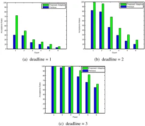
5.2. Impact of Deadline
In Figure 5, we analyzed the impact of the deadline on each flow acceptance rate in all comparative schemes. We take a short deadline from 1 to 3 while fix the numbers of flows as 6 in 6 clusters.
acceptance rate. This is because intra-cluster scheduling in previous scheme cannot use each other empty slots for clusters that have both IntraSend and IntraRecv flows. However, in adaptive scheme, although clusters have both IntraSend and IntraRecv flows, but if only one type of the flow is not ready at that time, then the other type of flows can make use of both IntraSend and IntraRecv slots.
1 2 3 4 5 6 0
10 20 30 40 50 60 70 80 90 100
Flow#
Acceptance Rates
Proposed−Adaptive Previous
1 2 3 4 5 6 0
10 20 30 40 50 60 70 80 90 100
Flow#
Acceptance Rates
Proposed−Adaptive Previous
(a) deadline = 1 (b) deadline = 2
1 2 3 4 5 6 0
10 20 30 40 50 60 70 80 90 100
Flow#
Acceptance Rates
Proposed−Adaptive Previous
(c) deadline = 3
Fig. 5.Simulation results w.r.t deadline
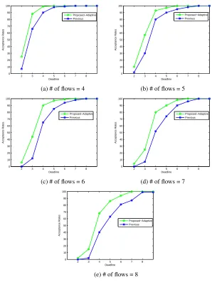
5.3. Impact of number of flows
In this section, we have analyzed the number of flows meeting deadline in comparative schemes by varying the flow numbers from 4 to 8. For each flow case, we run 100 random cases and count the number of cases where all flows are scheduled in their deadlines. The number of clusters are fixed to 6 while deadlines are vary from 2 to 8.
scheme, intra-cluster scheduling in adaptive schemes can make use of each other slots. So in adaptive scheme, if IntraSend flows in a cluster do not complete its scheduling in the allotted IntraSend slots, then IntraRecv slots can be utilized by IntraSend flows if its IntraRecv flows are not ready.
2 3 4 5 6 7 8 0 10 20 30 40 50 60 70 80 90 100 Deadline Acceptance Rates Proposed−Adaptive Previous
2 3 4 5 6 7 8 0 10 20 30 40 50 60 70 80 90 100 Deadline Acceptance Rates Proposed−Adaptive Previous
(a) # of flows = 4 (b) # of flows = 5
2 3 4 5 6 7 8 0 10 20 30 40 50 60 70 80 90 100 Deadline Acceptance Rates Proposed−Adaptive Previous
2 3 4 5 6 7 8 0 10 20 30 40 50 60 70 80 90 100 Deadline Acceptance Rates Proposed−Adaptive Previous
(c) # of flows = 6 (d) # of flows = 7
2 3 4 5 6 7 8 0 10 20 30 40 50 60 70 80 90 100 Deadline Acceptance Rates Proposed−Adaptive Previous
(e) # of flows = 8
Fig. 6.Simulation results w.r.t flow
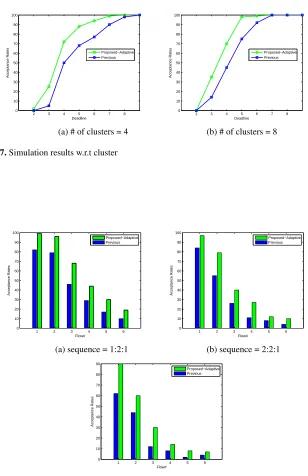
5.4. Impact of number Clusters
2 3 4 5 6 7 8 0 10 20 30 40 50 60 70 80 90 100 Deadline Acceptance Rates Proposed−Adaptive Previous
2 3 4 5 6 7 8 0 10 20 30 40 50 60 70 80 90 100 Deadline Acceptance Rates Proposed−Adaptive Previous
(a) # of clusters = 4 (b) # of clusters = 8
Fig. 7.Simulation results w.r.t cluster
1 2 3 4 5 6 0 10 20 30 40 50 60 70 80 90 100 Flow# Acceptance Rates Proposed−Adaptive Previous
1 2 3 4 5 6 0 10 20 30 40 50 60 70 80 90 100 Flow# Acceptance Rates Proposed−Adaptive Previous
(a) sequence = 1:2:1 (b) sequence = 2:2:1
1 2 3 4 5 6 0 10 20 30 40 50 60 70 80 90 Flow# Acceptance Rates Proposed−Adaptive Previous
(c) sequence = 3:2:1
fixed to 6. We run 100 random cases for each cluster number and count the number of cases where all flows are scheduled in their deadlines.
As show in Figure 7, if lower number of clusters that have high intra-cluster interfer-ence is assumed, less numbers of flows are scheduled in the available intra-cluster slots. But, as the number of cluster increases, the intra-cluster flows interference is reduced. Therefore, more flows are scheduled in the intra-cluster slots. For eight clusters, the ac-ceptance rate decreases due to high interference between the CHs.
Compared to the previous scheme, the adaptive scheme shows higher acceptance rate. This is because the allocated intra-cluster slots are insufficient for clusters that have high intra-cluster interference. Therefore, in this case, the adaptive scheme takes the advantage of intra-cluster schedule. For instance, in adaptive scheme for clusters that have high IntraSend flows interference, then these flows cannot be completely scheduled in allocated IntraSend slots so it is possible to use IntraRecv slots. On the other hand, the intra-cluster scheduling can only utilize their allocated slots and do not utilize slots of one another for clusters that have high intra-cluster interference in previous scheme. Due to this problem in previous scheme, intra-cluster flows waste each other empty slots and more flows miss their deadlines.
1 2 3 4 5 6 0
10 20 30 40 50 60 70 80 90 100
Flow#
Acceptance Rates
Proposed−Adaptive Previous
1 2 3 4 5 6 0
10 20 30 40 50 60 70 80 90 100
Flow#
Acceptance Rates
Proposed−Adaptive Previous
(a) sequence = 1:2:1 (b) sequence = 1:2:2
1 2 3 4 5 6 0
10 20 30 40 50 60 70 80 90 100
Flow#
Acceptance Rates
Proposed−Adaptive Previous
(c) sequence = 1:2:3
1 2 3 4 5 6 0
10 20 30 40 50 60 70 80 90 100
Flow#
Acceptance Rates
Proposed−Adaptive Previous
1 2 3 4 5 6 0
10 20 30 40 50 60 70 80 90 100
Flow#
Acceptance Rates
Previous Proposed−Adaptive
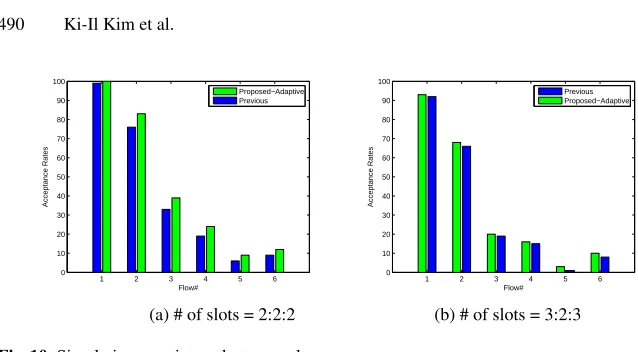
(a) # of slots = 2:2:2 (b) # of slots = 3:2:3
Fig. 10.Simulation w.r.t intra-cluster results
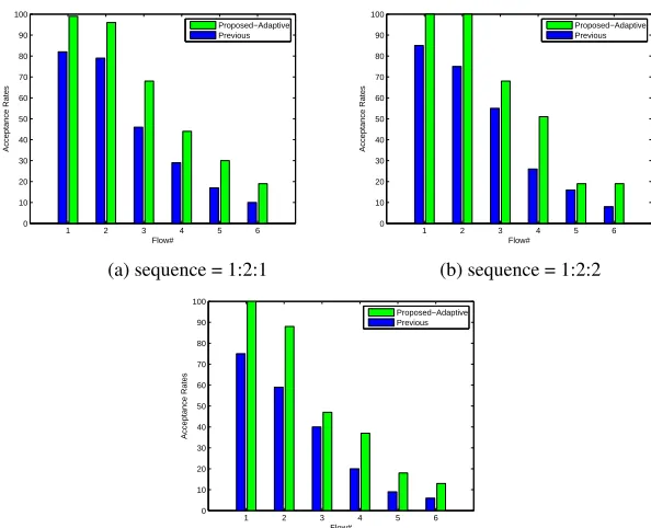
5.5. Impact of IntraSend/IntraRecv time slots
To analyze the performance of intra-cluster scheduling of adaptive and previous scheme, the time slots for both IntraSend and IntraRecv scheduling are varied while number of flow is fixed to 6 for six clusters. In Figure 8, we show the analysis of the IntraSend scheduling of above comparative scheme when IntraSend time slots are varied from 1 to 3 while the IntraRecv time slots are fixed to 1. As shown in Figure 8(a)-(c), the acceptance rate of all schemes decreases as the number of IntraSend slots increases. This is because most of the IntraSend slots are unused when the flows already reach their source CHs. However, the adaptive scheme has higher acceptance rate than previous scheme. This comes to insufficient slot for IntraRecv scheduling which allocates one slot.
Since the IntraRecv scheduling cannot utilized the IntraSend slots in previous scheme due to static scheduling, more flows are likely to miss their deadlines. Similarly in Figure 9, for the analysis of IntraRecv scheduling of comparative scheme, the IntraRecv time slots are varied from 1 to 3 while IntraSend time slots are fixed to 1. As shown in accep-tance rate of the adaptive IntraRecv scheduling, they reveal higher rate than the previous IntraRecv scheduling. Because the allocated IntraSend slot is not sufficient for IntraSend scheduling, so the adaptive IntraSend scheduling utilizes slots from IntraRecv slots while previous scheme wastes these IntraSend slots. As a result, more flows miss their deadlines in the previous scheme.
In Figure 10, IntraSend and IntraRecv have the same ratio of time slots. As the number of intra-cluster slots increases, performance of both schemes decreases because of the unused slots. Moreover, performance of proposed scheme becomes similar to previous scheme as the number of time slots increases. When allocated slots are sufficient for intra-cluster scheduling, proposed scheme and previous scheme do not utilize Intra-cluster slots.
6.
Conclusions
allocated to other flows. Simulation results also were presented to prove the suitability of the proposed schemes in many different aspects. Related to this work, further research work will be focused on how to extend proposed scheme in more realistic model. Also, a new routing protocol considering sensor node’s constraints will be concerned for proposed scheme.
Acknowledgments.This work was supported by Basic Science Research Program (2015R1D1A1 A01056979) through the National Research Foundation of Korea (NRF) funded by the Ministry of Education and Sur University College,Sur, Oman.
References
1. Akyildiz, I.F., Su, W., Sankarasubramaniam, Y., Cayirci, E.: A survey on sensor networks. IEEE Communications Magazine, 40(8), 102–114 (2002)
2. Ali, G., Kang, S.K., Kim, K.H., Kim, K.I.: Towards cluster-based real-time flow scheduling in interference-aware wireless sensor networks. In: Proceedings of the IEEE 16th International Conference on Computational Science and Engineering (CSE),. pp. 523–530. IEEE, Sydney, Australia (2013)
3. Bellavista, P., Cardone, G., Corradi, A., Foschini, L.: Convergence of manet and wsn in iot urban scenarios. IEEE Sensors Journal, 13(10), 3558–3567 (2013)
4. Camilo, T., Silva, J., Rodrigues, A., Boavida, F.: Gensen a topology generator for real wireless sensor networks deployment. Santorini Island, Greece (2007), [Online]. Avail-able:http://link.springer.com/chapter/10.1007
5. Cao, X., Chen, J., Xiao, Y., Sun, Y.: Building-environment control with wireless sensor and actuator networks: Centralized versus distributed. IEEE Transactions on Industrial Electronics, 57(11), 3596–3605 (2010)
6. Choe, H.J., Ghosh, P., Das, S.K.: Qos-aware data reporting control in cluster-based wireless sensor networks. Computer Communications, 33(11), 1244–1254 (2010)
7. Choi, H., Wang, J., Hughes, E.A.: Scheduling for information gathering on sensor network. Wireless Networks, 15(1), 127–140 (2009)
8. Ergen, S.C., Varaiya, P.: Pedamacs: power efficient and delay aware medium access protocol for sensor networks. IEEE Transactions on Mobile Computing, 5(7), 920–930 (2006) 9. Fattah, H., Leung, C.: An overview of scheduling algorithms in wireless multimedia networks.
IEEE Wireless Communications, 9(5), 76–83 (2002)
10. Hill, J., Szewczyk, R., Woo, A., Hollar, S., Culler, D., Pister, K.: System architecture directions for networked sensors. ACM SIGPLAN, 28(5), 93–104 (2000)
11. Kang, H., Zhao, Y., Mei, F.: A graph coloring based tdma scheduling algorithm for wireless sensor networks. Wireless Personal Communications, 72(2), 1005–1022 (2013)
12. Lan, K., Chou, C., Wang, T., Li, M.: On the efficiency of cluster-based approaches for mo-tion detecmo-tion using body sensor networks. Computer Science and Informamo-tion Systems, 8(4), 1051–1071 (2011)
13. Lotfinezhad, M., Liang, B., Sousa, E.S.: Adaptive cluster-based data collection in sensor net-works with direct sink access. IEEE Transactions on Mobile Computing, 7(7), 884–897 (2008) 14. Mottola, L., Picco, G.P., Ceriotti, M., Guna, S., Murphy, A.L.: Not all wireless sensor networks are created equal: A comparative study on tunnels. ACM Transactions on Sensor Networks, 7(2), 15:1–15:33 (2010)
16. Saifullah, A., Xu, Y., Lu, C., Chen, Y.: Real-time scheduling for wirelesshart networks. In: IEEE 31st Real-Time Systems Symposium (RTSS),. pp. 150–159. IEEE, San Diego, California (2010)
17. Shi, L., Fapojuwo, A.: Tdma scheduling with optimized energy efficiency and minimum delay in clustered wireless sensor networks. IEEE Transactions on Mobile Computing, 9(7), 927–940 (2010)
18. Subramanian, R., Lloyd, E.L.: Scheduling algorithms for multihop radio networks. IEEE/ACM TRANSACTIONS ON NETWORKING, 1(2), 166–177 (1993)
19. Torfs, T., Sterken, T., Brebels, S., Santana, J., van den Hoven, R., Spiering, V., Bertsch, N., Trapani, D., Zonta, D.: Low power wireless sensor network for building monitoring. IEEE Sensors Journal, 13(3), 909–915 (2013)
Gohar Ali received Ph.D degree from Gyeongsang National University, Jinju, Korea. He is currently with Sur University College,Oman. His research interests include sensor networks and real-time systems.
Kyong Hoon Kimreceived his B.S., M.S., and Ph.D. degrees in Computer Science and Engineering from POSTECH, Korea, in 1998, 2000, 2005, respectively. Since 2007, he has been an associate professor at the Department of Informatics, Gyeongsang National University, Jinju, Korea. His research interests include real-time systems, Grid and Cloud computing, and security.
Ki-Il Kimreceived M.S. and Ph.D. degrees in Computer Science from ChungNam Na-tional University, Daejeon, Korea. He is currently with the Department of Informatics at Gyeongsang National University. His research interests include ad hoc and sensor net-works.