Radiotherapy Conformal Wedge Computational
Simulations,Optimization Algorithms, and Exact Limit
Angle Approach
F Casesnoves MSc (Physics) MDIIIS International Institute of Informatics and Systemics (Individual Researcher Member)
ABSTRACT
Radiotherapy wedges constitute an important group within the generic classification of so-called Beam Modification Devices (BMD). Wedges are subdivided into Static, Dynamic, and Omni Wedges sug-groups. The standard static wedge attenuates the beam progressively, in such a way that the dose delivery is higher at the thin side, and lower at the broader side. The slope of the inferior surface has the geometry of the hypotenuse of a triangle, formed by the lateral wall of the wedge. Conformal/Standard radiotherapy wedges [refs 3-7,Casesnoves 2005] present several bioengineering-industrial design difficulties to obtain an optimal beam/beamlets-IMRT upper-surface radiation distribution,avoiding that them could emerge undesirably from lateral walls instead the lower wedge plane.We calculated the improved exact beamlet limit-angle mathematical method for a standard/conformal wedge filter design.It was developed with basic mathematical algorithms,geometrical design,and Numerical Simulations linked to this mathematical formulation.All that was done using the AAA algorithm integral attenuation exponential factor [AEF],which modulates the convolution kernel of the integral dose delivery.Results comprise the geometrical design of the conformal wedge,showed in several sketches,and simulations with appropriate software. In addition,a series of geometrical formulas/tables for the beamlets limits,trigonometric AEF background,and mathematical formulation with the simulations of the AEF for a 2-steps conformal wedge are obtained.
Keywords:Dose,Attenuation Exponential Factor (AEF) Simulations, Nonlinear Optimization.
1.-INTRODUCTION
Wedge filters (WF) constitute a common medical device used in Radiation Therapy,Inverse/Forward Treatment Planning Optimization (TPO), to conform tumor shape during radiation delivery.They belong to the generic group of Beam Modification Devices (BMD) [3,4].The WF function is to attenuate the radiation beam in increasing magnitude,usually along the transversal direction to the photon-beam. As a result, the dose delivery magnitude forms a curved distribution in that transversal direction for each radiation-depth value within the photon dose-deposition region. Classical wedges geometry have a straight sloping face corresponding to the hypothenuse of the triangle defined by the lateral sides. The clinical problem in TPO is, in occasions, to optimize the dose using WF, but the shape of the WF not always conforms the necessary geometrical conditions for the optimal tumor radiation. In this paper we present a Mathematical-Computational Model/Design for a Conformal Wedge Filter1, (CWF ) that has a sloping geometry divided into several non-continuous steps. The dose distribution in these types of wedges changes its shape for a more conformal radiation distribution, if the tumor presents irregular geometry/contour, rather non-spherical.Since the manufacturing/engineering design for these devices is simple/understandable, we focus the paper on the mathematical/geometrical/modeling formulation to carry out the design with engineering precision, obtain an optimal radiation dose, and implement the algorithm into the planning system software. It was shown mathematically the exact Limit angle method for rectangular collimators windows (square window is a particular case from this one), and optimal geometrical curves
1
The Conformal Radiotherapy Wedge was mathematically/physically designed by F Casesnoves in July 2005,Madrid City.Computational/Numerical Simulations were carried out at Denver,October 2012.Patent in Pending Process.In references, new Radiation Medical Physics improvements in conformal wedge design.(ellipses) within the exact LA polygon at superior/inferior wedge surfaces/planes. Previously, the classical Ulmer and Harder approximation for wedge-path of the beam is sharply explained with geometrical and algebraic proofs; the intention is to show the precision evolution towards a more accurate formula, starting from this initial good approximation. It was developed a mathematical formula to avoid non-symmetrical/irregular beam attenuation created by the alloy steps, that is, to sort the so-called double-attenuation (Fig,10).Additionally, we show computational simulations/graphics of the Attenuation Exponential Factor (AEF,Equation(8)) to be compared with classical wedge filters. The aim of this Technical Paper is, primarily, on the mathematical formulation that could be used to design/manufacture a conformal wedge model. The second part is related to simulations of the AEF distribution to prove, in theory, that a conformal wedge gets more precise dose distribution when the tumor contour is not spherical, which is the frequent clinical case.
2.-THE AAA ALGORITHM. MATHEMATICAL FORMULATION
The Analytic Anisotropic Algorithm, AAA, is a well-known and extensively used Superposition-Convolution Model in RT. AAA is is evolved from an initial Integral Superposition Convolution Model, whose parameters were optimized using large Monte Carlo experimental data in water. The starting Physical Equation to develop the model [31-34] was a Yukawa Kernel based on the formulation structure of the classical Yukawa Gaussian Potential for Electromagnetism, as follows,
Equation (1)
where Dp (r,z) the absorbed dose, normalized to one photon, r is the radial coordinate
Eq (2)
in the transverse plane at depth z. The characteristic function I(z) denotes the area integral of the dose over the transverse plane of the pencil beam at depth z, normalized to one photon, and
Eq (3)
is the mean square radial displacement of the profile at depth z. Next, a mathematical development based also in experimental data and Fourier Transform, was carried out [31-34], to transform the initial formula on a triple sum of Gaussians (Superposition) from the initial simple Gaussian, and optimize the coefficients according to photon beam experimental data. As a result, the Pencil Model Dose at a depth z and into an almost differential cylinder (Triple Gaussian Pencil Beam) whose diameter is 2r is,
2 2
r= x + y ;
2 2( )
2
( , )
( )
;
( )
r z
p
c
D r z
I z
e
z
σσ
−
=
2;
σ
© 2014 IJSRSET | Volume i | Issue i | Print ISSN : 2395-1990 | Online ISSN : 2394-4099
Themed Section:
Science
Eq (4)
The constants here are normalized in such a way that
Eq (5)
all the parameters are tabulated [31-34]. The derivation of the coefficient ck with the help of the Fourier transform, have already been described in the papers [31-32]. Tabulations of I(z),σk(z), and ck , based on Monte Carlo calculations of photon pencil beams for Co-60 gamma radiation and bremsstrahlung from 6 to 18 MV, have already been published [31-32]. This triple-Gaussian representation of the pencil beam has been chosen because its convolution with the photon flux distribution Ф (x,y,z) at depth z can be analytically performed in many practical cases. An important contribution to the saving of computer time and storage space is thereby achieved, because numerical convolutions or applications of look-up tables from their fitting formulas are partially avoided. The analytical form of the resulting dose distributions may also offer other, yet unknown, applications. The triple-Gaussian pencil beam approach can be applied to radiation beam profiles that represent rectangular satellite blocks and wedge filters, as it is the case of this paper. The derivation of the coefficients ck with the help of the Fourier transform, have already been described in the papers [32-34]. The term 'Superposition' comes from the sum of three Gaussians into the integral. The term 'Convolution' comes from the mathematical transformation carried out into the Dose-Deposition Kernel at the Integral. With this Triple Gaussian Dp (r,z), a Kernel K (x,y,u,v) was constructed to
implement the dose term into the integral expression for the initial Superposition-Convolution Model in water, and then, the integral dose results in general as follows,
Eq (6)
where I(z) is the area integral of the absorbed dose over a plane perpendicular to the pencil beam axis at depth z per incident photon [33], Φ is the photon fluence distribution of the beam per unit of intensity, and K is the kernel expression corresponding to the PBM, which is called the PB dose kernel, and describes the spatial distribution of the absorbed energy. This kernel could perfectly include any other PBM, for example the classic Anesjö model [1] or others. Now we focus on the aim of this research. The complete Triple Gaussian Pencil beam Model for one IMRT beamlet in water [Ref 2], when using wedges of angle α and taking into account the Collimator Divergence Angle (usually very small), θ then reads [8],
Eq (7) [erratum, limits of integral -a',a',-b',b']
where x1', y1', z', u1', u2' , are the bixel dose coordinates [Ref (2)] This is the formulation of the AAA algorithm in water. For inhomogeneous tissues, larger formulation that is not used in this contribution is applied. The AAA algorithm has evolutioned significantly from the initial model in water. A number of correction factors have been introduced to implement it into the Planning System (usually Eclipse, Varian). The determinations of algorithms
for inhomogeneous tissue formulation correspond to next publications. However, it is obliged to note that in human tissue the precise dose, with the AAA model, is a sum of three main integral factors [ref], namely, primary photons, extra-focal photons, and contaminating electrons. In addition, modern fitting of AAA model uses a summatory of four Gaussians instead three [ref 29.1 ]. Once these considerations/updates are explained, we step towards the mathematical model construction for the specific conformal wedge considering only at this stage primary photons in water.
3.-GEOMETRICAL-TRIGONOMETRICAL DEMONSTRATION OF CLASSICAL ATENUATION
EXPONENTIAL FACTOR 2D APPROXIMATION
Previously to determine the wedge/conformal wedge algorithm(s), the complete geometrical proof of the AEF approximation of Ulmer and Harder, [7], is proven. This good approximation was intended to obtain an analytical solution for Eq [9], which is an advantage for software dose delivery and running/planning-time calculations both numerical and analytic. The inconvenient of this method is that the variation of path through the wedge along coordinate v is supressed. This fact causes, as it will be shown, underdosage in planning calculations, because the AEF is higher in absolute value than it should be. Therefore, we get the impression that the dose delivered is correct, and it is not totally precise, it is lower than optimal.
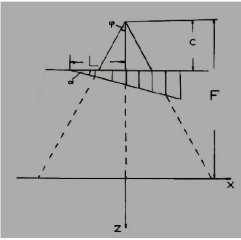
In Fig 2, pictured, the geometrical steps to prove the AEF approximation [7]. We detail the mathematical 2D path development proof as follows,
the classical notation of 2D wedge path by Ulmer and Harder is given in Fig [1],where L is distance from edge to central-beam, φ angle of beam-divergence, C distance from focus to wedge plane, and F distance from focus to dose-delivery zone.
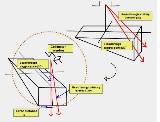
Fig 1.-Classical 2D notation for wedge-path integral exponential factor.In Fig 3 it is sketched the error that is taken using this approximation and in Eq (7.5) the recent solution for this exact path measurement is given in 3D. Parameters are included in Eq (7.1).As said, u,v are beam output size coordinates,z depth,L half wedge length,c output collimator-wedge surface distance,F total filter length,α wedge angle,φ beam/beamlet divergence angle.The constant µw is tabulated for different LINAC Photon-Energies.
Now we sketch in Fig 2 the calculations that result in exponential factor (AEF) of Eq 8.That is, a nonlinear function,
2 2
3
( ) 2
1
( , ) ( ) ;
( ) k
r k
z k
p
k k
c D r z I z e
z
σ
σ
= −
=
=
∑
( , , ) ( ) ( , , ) ( , , ) ;
D x y z I z x y z k x y z ds
∞ ∞
− ∞ − ∞
=
∫ ∫
Φ3 1
1; k
k k
c
=
= =
∑
2 2 2
1 1 2 2
2 2
1 2 2 2 ' 1 2
3
(( ' ' ) ( ' ' ) )/ ( ')
1 2
2 1
( ' , ' , ')
( , ')
( , , ' , ' , ')
'
' ;
( ')
k
a b
z
a b
x u x u z
k
k k
D x
x
z
I
z
u u
z
c
e
du du
z
σ
α
α θ
π σ
− −
− − + −
=
=
Φ
×
×
Eq (7.1)
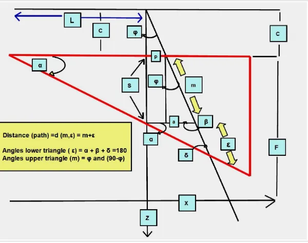
Fig 2.-basic Geometrical-mathematical demonstration sketch for Eq 7.1.
The mathematical-geometrical analysis for getting Eq 7.1 , setting basic trigonometric principles, reads,
Eqs (7.2)
to continue with distance decomposition, it is necessary to carry out a series of trigonometric calculations rather long, but convenient for future improved approximations in 3D,note that in this contribution we develop the method for the broad part of the wedge,and similar proof is applicable for the thin part in future contributions,
Eqs (7.3)
and the final stage is to develop, simplify, and sum part (1) and part (2),
Eqs (7.4)
which is the numerical value of the exponential of Eqs 7.1 and 8, and has to be multiplied by the attenuation coefficient of the wedge material, μw .
Therefore, the 2D approximation for wedge beam-path has been proven. However, it is mathematically convenient to show why a 3D calculation [Refs, 2,5], is demanding to improve the planning system software and avoid virtual underdosage. In Fig 3 it is sketched the difference between the 2D and 3d approximation with a graphical idea of the error. As it was shown in previous contributions, the 3D path D, through the wedge reads,
Eq (7.5) sin cos( ) sin cos( )
( , , )
( , , )
( , , )
( , , , );
( , , , )
;
w w w u cu L F z u cu L F zu v z
u v z
e
u v z
f u z
with
f u z
e
α µ α ϕ α µ α ϕ
α ϕ
α ϕ
− × ± × + + − × ± × + + Φ
= Φ
×
×
= Φ
×
=
° ° °=
= +
+ + =
=
+
=
- +
=
+
+
+
=
=
+
dis tance
d (m,ε)
m ε ;
angles lower triangle,
α β δ
180 ;β
90
φ;
δ
90
(α φ);
sin(δ)
cos(α φ);
sine theorem,
ε
(p a)
(p a)
;
sin(α)
sin(δ)
cos(α φ)
é - ù ê ú = ´ ´ê + + =ú + ë û é - + ù ê ú = + ´ ´ê ú= ë û = ´ ´ +
sin(α) cos(α)cos(φ) sin(α)sin(φ) sin(α)
(1) L tan(α)
cos(α φ) cos(φ)sin(α) cos(φ)
sin(α) cos(α)cos(φ) sin(α)sin(φ) sin(α)sin(φ) L tan(α)
cos(α φ) cos(φ)sin(α)
sin(α) cos(α) L tan(α) cos(α φ) é ù ê ú = ´ ê ú + ë û + = + ´ = = = é ù ê ú = ´ê ú + ë + û é ù ê ú + = + ´ ±ê + ú ë û sin(α) L; sin(α) cos(α φ)
sin(α) u F z
(2) p (u sin g proportional triangles, )
cos(α φ) p C
sin(α) Cu
; cos(α φ) F z
sin(α) Cu
(1) (2) L ;(caused by the sign change in
cos(α φ) F z
broad and thin parts of the wedge);
sin(α) cos(α)cos(φ) sin(α)sin(φ) sin(φ)
(1) L tan(α)
cos(α φ) cos(φ)sin(α) cos(φ)
sin(α) cos(α)cos(φ) sin(α)sin(φ) sin(α)sin( φ) L tan(α)
cos(α φ) cos(φ)sin(α)
sin(α) cos(α)
L tan(α)
cos(α φ) s
é - ù ê ú = ´ ´ê + ú= + ë û é - + ù ê ú = ´ ´ê ú= + ë û = ´ ´ + sin(α) L; in(α) cos(α φ)
é ù ê ú = ´ ê ú + ë û = = = + = + = + + = = + + = + =
p C tan(φ); a S tan(φ); S L tan(α); L tan(α)
(p a) (C S) tan(φ); and m ;
cos(φ)
(C S) tan(φ) tan(φ) (C L tan(α)) sin(α)
then,ε sin(α) ;
cos(α φ) cos(α φ)
we compose the total dis tan ce with some arrangements, d (m,ε) m ε;
sin(α) d cos é + æç ö÷ ù ê ÷ ú ´ê ççç ÷÷+ + ú + êë è ø úû é æç + ö÷ù ê ú÷ = + ´ê ççç ´ + ÷÷ú è ø ê ú ë û =
cos(α φ) L tan(α)
tan(φ) (C L tan(α)) ;
(α φ) sin(α) cos(φ)
for easy calculation, we decompose such as,
sin(α) cos(α φ) 1
(1) L tan(α) tan(φ) ;
cos(α φ) sin(α) sin(α)
sin(α) (2)
Fig 3.-Graphical difference/error-path when using 2D pproximation compared to 3D determination. If we take always the AEF approximation of Eq (7.1), in the sagittal plane, there is an error for less magnitude (blue brackett) in the path-distance through the wedge.
4.-METHODS/MODEL ALGORITHM/SIMULATIONS
The geometrical design of 1-step and 2-step conformal wedges is not complicated because it corresponds to basic irregular polyhedral design. In addition, we used trigonometrical calculations to determine the δ angle to avoid double attenuation effect in 3-steps conformal wedges.
The dose integral formula, when using wedges (Eqs [8,9]), has an additional AEF (Eq [8]) that gives the attenuation caused by the wedge alloy. This exponential modulates the kernel of the dose (the triple Gaussian in this AAA algorithm).In this way,to avoid hot spots at the borders of the tumor is better got with a conformal wedge; because it is possible to use a broader part at the tumor border (more attenuation compared to standard wedges, less dose), joint to a thinner part for the main volume of the tumor (less attenuation compared to standard wedges). It is intended to explain sharply this point by using the Superposition Principle for Radiation Dose in Figure (3). We used the classical AAA Radiotherapy Dose Distribution for Pencil Beam Model (water),so-called Anisothropic Analytic Algorithm, as previously [1,2,4]. Simulations are made taking the AEF that multiplies the convolution integrand part that corresponds to the generic AAA Dose-Delivery Integral Equation (8) [4]. Therefore, it is possible to extrapolate/hypothesize the theoretical results for the comparison of the dose distribution at a depth z in the x direction (internal-external,anatomically speaking), from the center of tumor towards the peripherical region (Fig 7.1,12). The center is less attenuated by the AEF, and the border is more attenuated by the AEF, and this, mathematically, will occur also with the dose distribution (Superposition Principle). The AEF in 2D (we denote 2D, according to [2]) formula, which modifies Photon-Fluence Distribution, reads [7],
Eq (8)
where u,v are beam output size coordinates,z depth,L half wedge
length,c output collimator-wedge surface distance,F total filter length,α wedge angle,φ beam/beamlet divergence angle.The constant µw is tabulated [4],for different LINAC
Photon-Energies.This Photon-Fluence,for wedges use,is implemented into the AAA Dose delivery Fundamental Formula (primary photons in water) as follows,
Eq (9)
where I(z) is Beam Intensity,ck and σkare constants tabulated
through optimization [4], and u,v,are output collimator coordinates. According to all this,the Mathematical Model Algorithm is,
Eq (10)
The functions fK correspond to the defined function f in [Eq (1)
].And we have divided the wedge surface in [1,K] intervals corresponding to every step, the total length of the wedge is 2L. With this formulation, it is mathematically possible to set a Nonlinear Multi-Objective Function to optimize the given parameters of the Conformal Wedge in Eq (10), using Eqs (8,9 ).Tikhonov Regularization2 with penalty and smooth term functions is applied in this nonlinear programming. This formulation will be developed/presented in subsequent publications. In consequence, a series of AEF values related to u coordinate distribution programs and graphics have been done. Simulation data is:field size 30x30cm2,18MEV LINAC Photon-Energy,depth z=8cm, see [Fig 2].
4.-EXACT GEOMETRICAL METHOD FOR LA DETERMINATION
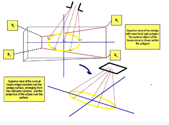
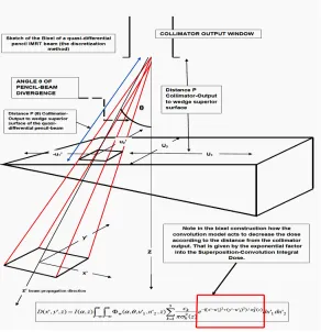
In Figs [4,5] we detail the geometrical method for LA exact calculation. Standard wedge dimensions from ref 7, a,b,c. This approach constitutes an improvement related to previous approximations [refs], based on two main points. The real physical shape of the LINAC beam is approximately an elliptic cone, not a circular one as in [refs 3,3.1], caused by the rectangular geometry of the collimator window. Besides, before reaching the wedge, the beam has also interact/be shaped by jaws, flattering filter, ionization chamber, multileaf collimator (if used), and eventually dynamics wedges. The use of divergent-cutting planes draw a simple intersection-polygon over the wedge surface, which is the mathematically exact border for LA. We start with the plane PAB [Figs 4,5], so the line PB, symmetric to PA,
2 Tikhonov regularization, originally developed with a Sobolev Norm (Sobolev Spaces), constitutes the base of the nonlinear optimization with least-squares for the mathematical/computational framework of this article. Tikhonov Regularization Theory sets the mathematical
' '
' '
D(x, y,z) I(z) a b w( , , ) a b u v z
− −
=
∫ ∫
Φ ×(
2 2)
23 ( ) ( ) / ( )
2 1
; ( )
k
k x u y v z
k k k
c e dudv
z σ π σ = − − + − = ×
∑
× sin cos( ) sin cos( ) ( , , ) ( , , ) ( , , ) ( , , , ); ( , , , ) ; w w w u cu L F z u cu L F zu v z u v z
e u v z f u z
with f u z e
α µ α ϕ α µ α ϕ α ϕ α ϕ − × ± × + + − × ± × + + Φ = Φ × × = Φ × =
1 1 1 1
1 1 ( , , , ) .... ( , , , ) ; .... ( , , , )
, , , ; 2
; k k k k
K
k k k k k k
k
f u z F u z
f u z
with every u L L and L L
and K is the number of wedge steps
Eqs (11)]
Now for the line PC {Fig],
Eqs [11.1]
we detail the intersection points at z=c by lines PB and PC
Eqs (12)
the points of the base, [Figs 4,5], AB and vector XPC draw the exact emerging border for the wedge [Figs 4,5]. The plane PBC contains the inferior border BM of the wedge. Furthermore, this PBC plane intersects with a line at z=0, setting, [Figs 3,4], the LA line complementary with the intersecting line of the plane PBA at z=0, [Figs 3,4].
Then we get at the wedge surface , [Figs 4,5], the polygon whose interior should restrain/include the radiation beam in order not to go over the Limit angle. If this condition holds, the beam/beamlets will not emerge from the lateral wedge walls [Figs 4,5]. The limiting points of this polygon,[Figs 4,5], are,
L 1 = ( a/2[(P/(P+c)] , b/2 [[(P/(P+c)] , 0 ); L 2 = ( a/2[(P/(P+c)] , (-b/2) [[(P/(P+c)] , 0 ); L 3 = ( (-a/2) , b/2 , 0 );
L 4 = ( a/2 ,(-b/2) , 0 );
Eqs (13)
In Fig 5,the notation of L has been changed by S letter.The elliptical section [Figs 4,5] of the beam cone should be within this region. It will define an elipse into these limits. An initial approximation for this curve is,
Eqs (14)
Note that the last equation opens an inverse determination of the collimator output distance, P, related to the Limit Angle, θL.. That is, we can select an appropriate Limit Angle θL.,and get the optimal collimator output distance
P
. Such as,Eq (15)
The optimal ellipse equation for LA conditions within this Limit Polygon (Figs 4,5), can be determined both with numerical methods and analytic geometry, and constitutes matter of next contributions.
Fig 4.-Exact Geometrical Sketch for LA, superior and inferior wedge planes. Note the difference between the superior and inferior plane and the limits of the polygons.Geometrical calculations are carried out with basic analytical geometry and algebraic geometry. For conformal wedges the method is similar, but we divided into each conformal wedge step. In new contributions the conformal wedge geometry mathematical development will be sketched and a series of equations for this special medical device [Casesnoves,2005] sharply explained. 0 (0,0, ); 1 (( a/ 2),( / 2),0);
and we get the line PC ; ( / 2) ( / 2) ( ) int sec int 0 i (( a/ 2),( / 2),0);
X P X b
x y z P
a b P
The er tion po at z X b
= - =
-+
= - =
-= =
-r r
r
Intersection of lines PB and PC at z c (inferior wedge plane), ((a/ 2),( / 2),c); (( a/ 2)(P c),( / 2)(P c),c);
PB PC
X b X b
=
= = - + +
r r
0 0 0
0 1
0 1 0 1 0 1
; (0,0, ); (a/ 2,b/ 2,C);
Resulting line PB, ;
( / ) ( / 2) ( )
0 ,int sec int, i ((a/ 2) ,(b/ 2) ,0);
x x y y z z
X P X x x y y z z
x y P z a b b P c
P P
At z er tion po X
P c P c
- = - = - = - =
- -
-+
= =
- -
-æ ö÷ æ ö÷
ç ç
= = ´èçç + ø÷÷÷ ´ççè + ÷÷÷ø
r r
r
(
)
2 2
2 2
1 2 1
1 1 1
2 2 2 2
1;
/ 2; ;
, ;
( ) ;
sin cos
( ) arctan ; y
x y
L
x y
where a b
a L L b L with L L L
ab in polar coordinates r
a b r
and P
P
q
q q
q
-+ =
= =
=
=
+ æ ö÷
ç = ç ÷÷çè ø÷
r r r
r
( ) ;
tan L
L
r P q
q
=
Fig 5.-Sharp geometrical-polygon sketch for circumscribed optimal ellipse linked mathematically to exact limit angle. Eqs (14). Note that for a square collimator-window or MLC rectangular-square geometry the technique is the same.
5.-RESULTS/COMPUTATIONAL SOFTWARE
In Figures 6.1 and 6.2 we show a basic geometrical design of a conformal wedge. Fig 6.1 presents a 1-step 2D conformal wedge, which does not have any double-attenuation design problem. Figure 6.2 details a 2-step 2D conformal wedge geometric design, that shows how the double-attenuation could become a dose engineering-precision difficulty. Double attenuation occurs when any divergent beamlet can collide with the notch of the step-discontinuity after emerging from the wedge-interior. This phenomenon cause an additional attenuation of the beamlet, and if the threshold between two consecutive steps is high, the double attenuation can be a source of error. According to Mathematical Formulation which is presented in Eqs1,2 (Trigonometry calculations),Double-attenuation angle δ Fig (5) is,
Eq (11)
where L is the half lateral length (standard) of the wedge,and factor m is defined by trigonometry with the distance from the step corner notch to the lateral wedge side, S is the distance to the wedge surface from step notch corner, and c [Ref 7] is the distance from collimator output to wedge surface.
Simulations of lateral 2D AEF magnitude distribution for 45º wedge are presented in Fig 7.1 related to u coordinate. In that pic,it is proven the adaptation of the AEF on the tumor contour threshold.The simulation was done with a standard wedge of 45º (standard size, [2]) modified to a conformal one, right broad part.The decrease of the AEF curves while wedge thickness increase, causes a dose-reduction towards the tumor edge since AEF multiplies the integrand triple-Gaussian principal convolution term. We explain Figs 7.1,8 in other words. The wedge-exponential factor (AEF) of the graph, multiplies within the integral the dose-convolution factor. The integral can be considered as a summatory of these multiplications. Therefore, if there is a threshold in the magnitude of the exponential (AEF), it is also projected by multiplication to the total dose. Software for simulations was carried out with specific Freemat 4.2 (Samit Basu GNU General Public License) subroutines.The matrices for the curves construction had to be modified/transposed sometimes to carry out mathematical operations. Basically, we have to design
the simulation program setting vectors for each step interval with the corresponding values of u coordinate and φ angles. After that, we use 2D graphics subroutines to implement the AEF formula with these vectors. Some special arrangements have to be carried out to join the curves together in one graph. The subroutines that were used were, among others, handle-based graphics and plot function.
6.-FORMER BEAM LIMIT DIVERGENCE ANGLE, CONCEPT, GEOMETRY, AND FORMULATION
In previous contributions [3,3.1,4], the LA was mathematically defined and developed for wedges. We detail here the main formulas and one sketch of LA, together with a picture of the so-called conformal wedge. Given a fixed collimator output to wedge surface distance, LA is defined as the maximum angle of divergence that can be reached by the whole radiation beam without emerging at any point of lateral walls of the wedge. Photon-Beam divergence angles values vary around 20 degrees. The Beam minimum divergence depends on the collimator design quality, and in general of the precision engineering manufacturing of the LINACs. LA is useful because of several reasons. Avoids hot spots, sub-optimal dose delivery, planning system software propagation errors, overdose at OARS, and repetition of planning work caused by sub-optimal dose delivery calculations. The LA for a conformal wedge calculation presents some additional difficulties. However, the primary approximation is to take as LA for a CWF he value of the deepest step of the wedge. Main formulation for LA in standard wedges is for the principal pencil beam [Ref 9],
with
Eqs (12)
where
from [Ref 9] , and
Eqs (13)
where P is the distance between the collimator output and wedge surface (perpendicular, [Ref 9]), r is the vector defined by coordinates u1 and u2 (wedge surface as in Figs (6.1, 6.2), alpha is the wedge angle, and theta is the beamlet divergence angle. These limiting geodesics are sketched in red in Fig (2.1). We have used the constraint for inferior geodesic [Ref 9] and Figs (1.1,1.2),
Eq (14)
Therefore, to make sure the components of the decomposed beam Fig have a correct output point the following conditions should hold
Eqs (15)
where a is the half-side of transverse maximum length of wedge, and c is collimator-wedge surface distance. Angle decomposition is sketched in Fig 9.
arctg L m ;
S c
δ = −
+
2 0
[ ]
[ ] u ;
L
r Geometrical arctg
P
θ = =
2 2 2
1 2
u + u = r ;
r b tan= − θ × tanα × +(b a) r( ) ;= θ
2 2
2
r b tan= − θ ×[tanα ×[ b − u + a]] r( ) ;= θ
2 2 2
1 2
u + u = b ;
1 arctg Pa2c ;
θ ≤
+
2 ;
a arctg
P c
θ ≤
+
7.-DISCUSSION AND CONCLUSIONS WITH CLINICAL-BIOENINEERING APPLICATIONS
The principal result in Figs shows geometrical formulation for exact LA. Elliptic cone and elliptic sections over upper-wedge surface.The method can be considered improved compared to previous contributions and applicable both on circular and elliptical radiation beam geometry.Standard/Conformal wedges manufacturing should be made for LINAC manufacturing holding these mathematical-geometrical constraints to avoid undesirable beam/beamlets emerging from lateral wedge sides. Clinical-Bioengineering applications go beyond only wedge filters, since MLC can be used combined with wedges for optimal dose distribution/delivery. All these formulas/algorithms are suitable to be implemented in planning-system software for Clinical Inverse/Forward Treatment Planning Optimization.
8.-PRINCIPAL REFERENCES
[1].-Casesnoves,F.'Exact/Approximated Geometrical Determinations of IMRT Photon Pencil-Beam Path Through Alloy Static Wedges in Radiotherapy Using Anisothropic Analytic Algorithm (AAA)’.Peer-reviewed ASME Conference Paper.ASME
2011 International Mechanical Eng
Congress.Denver.USA.IMECE2011-65435.2011.
[2].-Casesnoves,F.'Geometrical Determinations of Limit angle (LA ) related to maximum Pencil-Beam Divergence Angle in Radiotherapy Wedges’.Peer-reviewed ASME Conference Paper.ASME 2012 International Mechanical Eng Congress.Houston.USA.IMECE2011-65435.2011.
[3].- Casesnoves, F 'A Conformal Radiotherapy Wedge Filter Design. Computational and Mathematical Model/Simulation’ Casesnoves, F. Peer-Reviewed Poster IEEE (Institute for Electrical and Electronics Engineers), Northeast Bioengineering Conference. Syracuse New York, USA. April 6th 2013. Peer-Reviewed Poster Session on 6th April 2013. Sessions 1 and 3 with Poster Number 35. Page 15 of Conference Booklet.
[4].-Casesnoves, F. Mathematical and Geometrical Formulation/Analysis for Beam Limit Divergence Angle in Radiotherapy Wedges. Peer-Reviewed International Engineering Article. International Journal of Engineering and Innovative Technology (IJEIT) Volume 3, Issue 7, January 2014. ISSN:
2277-3754 ISO 9001:2008 Certified.
http://www.ijeit.com/archivedescription.php?id=27.
[5].- Sharma, SC. Beam Modification Devices in
Radiotherapy.Lecture at Radiotherapy
Department,PGIMER.India.2008.
[6].-Casesnoves, F.'Geometrical determinations of IMRT photon pencil-beam path in radiotherapy wedges and limit divergence angle with the Anisotropic Analytic Algorithm (AAA)' Casesnoves, F. Peer-Reviewed scientific paper, both Print and online. International Journal of Cancer Therapy and Oncology 2014; 2(3 ):02031. DOI:10.14319/ijcto.0203.1
[7].-Casesnoves, F.‘Radiotherapy Conformal Wedge Computational Simulations and Nonlinear Optimization Algorithms’. Casesnoves, F. Peer-reviewed Article, Special Double-Blind Peer-reviewed paper by International Scientific Board with contributed talk. Official Proceedings of Bio- and Medical Informatics and Cybernetics: BMIC 2014 in the context of The 18th Multi-conference on Systemics, Cybernetics and Informatics: WMSCI 2014 July 15 - 18, 2014 , Orlando, Florida, USA.
[8].- Casesnoves, F. ‘Large-Scale Matlab Optimization Toolbox (MOT) Computing Methods in Radiotherapy Inverse Treatment Planning’. High Performance Computing Meeting. Nottingham University. January 2007.
[9].-Casesnoves,F.‘A Computational Radiotherapy Optimization Method for Inverse Planning with Static Wedges’. High
Performance Computing Conference.Nottingham
University,.January 2008.
9.-GENERAL REFERENCES
[1] Ahnesjö A.,Saxner M., A. Trepp. 'A pencil beam model for photon dose calculations'. Med. Phys. 19, pp 263-273, 1992.
[2] Brahme, A. 'Development of Radiation Therapy Optimization'. Acta
Oncologica Vol 39, No 5, 2000.
[3] Bortfeld, T,Hong T, Craft, D, Carlsson F. 'Multicriteria Optimization in Intensity-Modulated Radiation Therapy Treatment Planning for Locally Advanced Cancer of the Pancreatic Head'.International Journal of Radiation Oncology and Biology Physics. Vol 72, Issue 4.
[4] Censor Y, and S A Zenios. 'Parallel Optimization: Theory, Algorithms and Applications'. UOP, 1997.
[5] Casesnoves, F. ‘Determination of absorbed doses in common radiodiagnostic explorations’.5th National Meeting of Medical
Physics.Madrid, Spain. September 1985.
reatment Planning’. Kuopio University. Radiotherapy Department of Kuopio University Hospital and Radiotherapy Physics Group. Finland. 2001. [6] Casesnoves, F. ‘Large-Scale Matlab Optimization Toolbox (MOT) Computing Methods in Radiotherapy Inverse Treatment Planning’. High Performance Computing Meeting. Nottingham University. January 2007. [7] Casesnoves, F. ‘A Computational Radiotherapy Optimization Method for Inverse Planning with Static Wedges’. High Performance Computing Conference. Nottingham University. January 2008.
[8].-Casesnoves, F 'Exact/Approximated Geometrical Determinations of IMRT Photon Pencil-Beam Path Through Alloy Static Wedges in Radiotherapy Using Anisothropic Analytic Algorithm (AAA)' peer-reviewed ASME Conference paper-poster. Proceedings of ASME 2011 IMECE (International Mechanical Engineering Conference) Conference. Denver, Nov 2011. CO, USA.2011.
[9] Casesnoves, F 'Geometrical Determinations of Limit Angle (LA) related to Maximum Pencil-Beam Divergence Angle in Radiotherapy Wedges' Casesnoves, F.Peer-reviewed ASME Conference Paper. ASME 2012 International Mechanical Engineering Congress.Houston.Nov 2012.USA.IMECE2012-86638.
[10.1] 'A Conformal Radiotherapy Wedge Filter Design. Computational and Mathematical Model/Simulation’ Casesnoves, F. Peer-Reviewed Poster IEEE (Institute for Electrical and Electronics Engineers), Northeast Bioengineering Conference. Syracuse New York, USA. Presented in the Peer-Reviewed Poster Session on 6th April 2013. Sessions 1 and 3 with Poster Number 35. Page 15 of Conference Booklet. April 6th 2013. [10.2] 'Geometrical determinations of IMRT photon pencil-beam path in radiotherapy wedges and limit divergence angle with the Anisotropic Analytic Algorithm (AAA)' Casesnoves, F. Peer-Reviewed scientific paper, both Print and online. International Journal of Cancer Therapy and Oncology 2014; 2(3):02031. DOI: 10.14319/ijcto.0203.1
[10.3]-‘Radiotherapy Conformal Wedge Computational Simulations and Nonlinear Optimization Algorithms’. Casesnoves, F. Peer-reviewed Article, Special Double-Blind Peer-reviewed paper by International Scientific Board with contributed talk. Official Proceedings of Bio- and Medical Informatics and Cybernetics: BMIC 2014 in the context of The 18th Multi-conference on Systemics, Cybernetics and Informatics: WMSCI 2014 July 15 - 18, 2014 – Orlando, Florida, USA.
[11] Censor, Y. 'Mathematical Optimization for the Inverse problem of Intensity-Modulated Radiation Therapy'. Laboratory Report, Department of Mathematics, University of Haifa, Israel, 2005.
[12] Capizzello A, Tsekeris PG, Pakos EE, Papathanasopoulou V, Pitouli EJ. 'Adjuvant Chemo-Radiotherapy in Patients with Gastric Cancer'. Indian Journal of Cancer, Vol 43, Number 4. 2006.
[13] Do, SY, David A, Bush Jerry D Slater. 'Comorbidity-Adjusted Survival in Early Stage Lung Cancer Patients Treated with Hypofractioned Proton Therapy'. Journal of Oncology, Vol 2010.
[14] Ehrgott, M, Burjony, M. 'Radiation Therapy Planning by Multicriteria Optimization'. Department of Engineering Science. University of Auckland. New Zealand.
[15] Ezzel, G A. 'Genetic and geometric optimization of three dimensional radiation therapy treatment planning'. Med. Phys.23, 293-305.1996. [16] Effective Health Care, Number 13. 'Comparative Efectiveness of Therapies for Clinically Localized Prostate cancer'. 2008.
[17] Haas, O.C.L.'Radiotherapy treatment planning, new systems approaches'. Springer Engineering.1998.
[18] Hansen, P. 'Rank-deficient and discrete ill-posed problems: numerical aspects of linear inversion'. SIAM monographs on mathematical modelling and computation, 1998.
[19] Hashemiparast, SM, Fallahgoul, H. Modified Gauss quadrature for ill-posed integral transform. International Journal of Mathematics and Computation. Vol 13, No. D11. 2011.
[20] Johansson, K-A , Mattsson S, Brahme A, Turesson I. 'Radiation Therapy Dose Delivery'. Acta Oncologica Vol 42, No 2, 2003.
[21] Kufer,K.H. Hamacher HW, Bortfeld T.. 'A multicriteria optimisation approach for inverse radiotherapy planning'. University of Kaiserslautern, Germany.
[22] Kirsch, A. 'An introduction to the Mathematical Theory of Inverse Problems'. Spinger Applied Mathematical Sciences, 1996.
[23] Luenberger D G. 'Linear and Nonlinear Programming 2nd edition'. Addison-Wesley, 1989.
[24] Moczko, JA, Roszak, A. 'Application of Mathematical Modeling in Survival Time Prediction for Females with Advanced Cervical cancer treated Radio-chemotherapy'. Computational Methods in science and Technology, 12 (2). 2006.
[25] Numrich, RW. 'The computational energy spectrum of a program as it executes'. Journal of Supercomputing, 52. 2010.
Cancer Institute, Vol 97, Number 2. 2005.
[27] Steuer, R. 'Multiple Criteria Optimization:Theory, Computation and Application'. Wiley, 1986.
[28] Spirou, S.V. and Chui, C.S. 'A gradient inverse planning algorithm with dose-volume constraints'. Med. Phys. 25, 321-323.1998.
[29] Sharma, SC. 'Beam Modification Devices in Radiotherapy'. Lecture at Radiotherapy Department, PGIMER. 2008.
[29.1].-Sievinen J, Waldemar U, Kaissl W. AAA Photon Dose Calculation Model in Eclipse™.Varian Medical Systems Report.Rad #7170A.
[30] Ulmer, W, and Harder, D. 'A triple Gaussian pencil beam model for photon beam treatment planning'. Med. Phys. 5, 25-30, 1995.
[31] Ulmer, W, and Harder, D. 'Applications of a triple Gaussian pencil beam model for photon beam treatment planning'. Med. Phys. 6, 68-74, 1996. [32] Ulmer, W, Pyyry J, Kaissl W. 'A 3D photon superposition/convolution algorithm and its foundation on results of Monte Carlo calculations'. Phys. Med. Biol. 50, 2005.
[33] Ulmer, W . Laboratory Report. Phys. Med. Biol. 50, 2005.
[34] Ulmer, W, and Harder, D. 'Applications of the triple Gaussian Photon Pencil Beam Model to irregular Fields, dynamical Collimators and circular Fields'. Phys. Med. Biol.1997.
[35] Ulmer, W, Schaffner, B. 'Foundation of an analytical proton beamlet model for inclusion in a general proton dose calculation system'. Radiation Physics and Chemistry, 80. 2011.
Figures 6.1,6.2 -Upper,basic geometrical design of Conformal Wedge Filter (1 and 2 notchs)and Angle-Step Geometry. Lower, 1-step Conformal wedge showing the principal beam (one pencil-beam) and a divergent pencil-beam.
Figure 8.-An sketch of the Superposition Principle for Standard Wedge
(upper),and for Conformal Wedge Conversion (lower).
Figure 9.-An sketch of the decomposed beam for LA calculations [refs 4,6,7].
Figure 10.-An sketch of the double-attenuation geometry calculations, related to Eq (11). L is in Eq (11) the half-length of the total transversal length of the wedge.
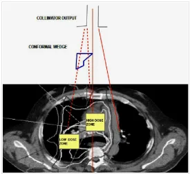
Figure 11.-A simple sketch of the dose distribution of a conformal wedge for a lung tumor (Google Images with paper author's composition/design).
Figure 12.-A simulation graphics to show the enhanced threshold of the AEF. Basically, we have to design the simulation program setting vectors for each step interval with the corresponding values of u coordinate and φ angles. After that, we use 2D graphics subroutines to implement the AEF formula with these vectors. Some special arrangements have to be carried out to join the curves together in one graph.