http://www.sciencepublishinggroup.com/j/wcmc doi: 10.11648/j.wcmc.20180602.11
ISSN: 2330-1007 (Print); ISSN: 2330-1015 (Online)
Beamforming Technique Assisted by Machine Learning
Algorithm for Next Location Prediction
Hussein Safwat Hasan Hasan, Humor Hwang
*Department of Information and Communications Engineering, Myongji University, Yongin City, Republic of Korea
Email address:
*
Corresponding author
To cite this article:
Hussein Safwat Hasan Hasan, Humor Hwang. Beamforming Technique Assisted by Machine Learning Algorithm for Next Location Prediction. International Journal of Wireless Communications and Mobile Computing. Vol. 6, No. 2, 2018, pp. 37-42.
doi: 10.11648/j.wcmc.20180602.11
Received: December 5, 2018; Accepted: January 2, 2019; Published: February 14, 2019
Abstract:
Technological improvement towards the development of location prediction advancement had attracted a great attention due to its broad application. Herein, intercalation of two widely scrutinized techniques were fused to form a synchronized location forecasting system. Using the underlying concept of beamforming (BF), an array of retro directive beams towards the phase sectioned field were emitted to determine the specific location of an entity or receiver. The receiver collects and sends back the data of beam emissions with respect to time and phase, machine learning (ML) technique were used to analyze the transcribed data to determine the phase with optimum beam reading that corresponds to the location of the receiver. Series of historical context will be analyzed by ML to predict the next location of the entity, emitting an array of signals pointing at the predicted location. Automatic location forecasting synchronization due to intricate systematic design were demonstrated. It should be noted that BF-ML technique collaboration for location prediction had never been reported before and driven by its advantages in wireless networking (such as elimination of interference and privacy issues) field of utilization can still be expanded.Keywords:
Machine Learning (ML), Beamforming (BF), Scans, Phase Delay, Tracking Algorithm1. Introduction
Forecasting the next location of the receiver through its historical motion is useful for creating smart applications. The advancement on the techniques on approximation and anticipation of the future position of the receiver enable the progression of location predicting application and services. Generally, wireless system monitors the location predicting system by gathering and providing them the necessary information prior application [1, 2]. In order to communicate with the receiver effectively, the sender should be intelligent enough to determine the position of the receiver at any point in time [3]. The idea of anticipating the location of the receiver by machine learning (ML) algorithms has already been established [4]. Status data of the receiver at specified time is recorded and analyzed accordingly and transcribe as context [5, 6]. Numerous machine learning techniques had been recognized towards the technological advancement of location forecasting [7], such as wireless communication
network (Wi-Fi), Global System for Mobile Communications (GSM) and Global Positioning System (GPS). And depending on the application, ML algorithms can be tuned and constructed to satisfy its purpose [8, 9].
Historical motion of the entity was gathered from several transitions, analysis of the labeled context features was supervised by ML classifications [10, 11]. The collected data about sequential movement were analyzed and interpreted to generate a suitable location prediction. Once forecasted position has been determine, the BF and ML system will synchronize the array of beam targeting and directing towards the proposed next location of the receiver, enabling the proposed system to have an auto-synchronization capability onto a repetitive cycle.
Location forecasting has garnered increased attention by deploying in location control expecting to boost the standard of the services. Therefore, the utilization of BF approach effectively manipulates the high-performance beam emissions channeled towards the receiver with reduced interference and elevated intensity. The proposed system addresses the issues governing privacy breach and reception dilemma of the next location prediction, the utilization of beamforming technique to forecast the succeeding position of the entity using the context of its current and previous location without invading the receiver’s privacy and eliminating the reception interference. New technique for the resolution towards the challenge in determination of the next probable location of an entity with ML-BF system had been scrutinized with advantageous properties such as auto-synchronization, avoidance of privacy violation and reception interference elimination.
2. Beamforming
Anticipating the possible location of an entity has been a challenge in the networking industry. Location forecasting has received a great attention due to its robust application in various discipline. Hence, the reason of applying beamforming technique observing the elevate performance of beam navigation to collect a lower level of interference with higher intensity [12]. Beamforming is defined as the spatial filtering wherein the suitable signal receptor that corresponds to group of antennas that can be used to maneuver the transmitted signals in a fix direction [13]. Various methods and technologies have been generated to focusing beam emissions towards the receiver direction to achieve an effective communication and tracking ability [14]. Time delay shift (time delay) and phase shift were the most common strategy to direct the beams projection whether in analog or digital mode. The time delay program can form and manipulate the beam by altering and adjusting the time delay pace that are independent from the steered frequency and bandwidth. The increase in normalized depends on the bandwidth B and the delay ∆t (variation in time of influx of the front wave at the receiving antenna due to the dimension of array) as described in the following expression.
∆
∆ (1)
Shown in Figure 1 a basic beamforming diagram, considering the signal reception of the antenna 1 at phase = 0,
the signal arrives at the antenna “n” leads in phase with n d sin α. This gives the description of the Array Propagation Vector that it comprises.
Figure 1. Beam forming diagram.
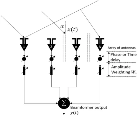
The signal can be manipulated in specific direction while on the other hand use of amplitude weights permits to steer the sidelobe intensity and neglect the control for radio intrusion rejection. At the beamforming system, antenna N can control the signal on the chosen direction and nullify (rejects beam manipulation) at optimum N-1 intrusive signals approaching from N-1 opposite directions.
∑ (2)
Wherein the radiation response S (α) at the array, while ξ=2π/λ and λ corresponds to the wavelength with the same weights all over the array, ( =1) in the diagram. The details of the direction of influx of signals can be discern as:
1 … … (3)
In this manner the Array Factor can be described as:
! ", $ (4) Hence, the main benefits of applying the beamforming is that numerous access is achieved through the space partitions, since a beamformer can manipulate its direction towards a certain signal, the beamformer focuses in a specific direction, the antenna’s capability to sense can be improved for a better signal to noise ratio, specifically when getting weak signals. And these properties are all attained electronically with no physical activity of the receiving antennas [15, 16].
3. The Proposal
the next location prediction, we historically log the places that the receiver visited with variations on the antennas beamforming phase at a given moment of time. The beamforming system is composed of array of antennas equipped with phase delay shifters as projected in Figure 2. Assisted by machine learning, shifters automatically navigate signals towards the receiver relying onto historical context. The forecasting is initiated by several scans with beam shifted on different phase delay settings in a certain amount
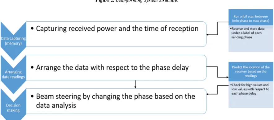
time having fixed amplitude, the receiver on the other hand will store the coming signals and transcribe the value of power and time under each phase Figure 3. The stored data of each scan is fed to the tracking algorithm to determine phase with the highest power received, the results were supplied to the machine learning algorithm to predict the next location of the receiver. The phase delay automatically directs the signals to the receiver based on the predicted phase value of the machine learning.
Figure 2. Beamforming System Structure.
Figure 3. The Tracking algorithm.
Providing a sequence of various places that comprises the necessary data needed for training. Considering % &' , … , ' ( to be the set of values of location visited, the ) &* , … , * ( will be the set of time records, and + &, , … , , ( to will be the set of context data, where , signifies as a set of featured pair values that are available at *-. The context details in our experiment are gathered by administrating a full scan starting from the lowest phase shift up to the highest phase with a firm gap in between each phase. The scanning outcomes represented as the assessed value of the delivered power to the receiver at a
specified amount of time as defined in the chart projected below.
./01.2' ∈ % 456% 78 '|) *-, + ,*2 *- , % ':, *- ;< (5)
location as a starting point.
4. Experimental Analysis
The performance of the proposed technology was analyzed and evaluate by implementing Python algorithm. In the evaluation, the pygame library were applied to create and simulate the virtualization of the proposed phenomenon. An array of antennas was set and will serve as the beamformer transmitter (with number of antennas from 1 to N), once the receiver transmitted a signal as shown in Figure 4.
The power will be transmitted and capture through the antennas. To calculate the performance of the system, free-space path loss (FSPL) were expressed through the value of power losses and corresponds to the reciprocal of the power gain.
! 5% 4=> <? (6)
Where λ is stands for the speed of light while d will be determine by applying the distance between two circles formula.
@ A 22 C 21 ?D E2 C E1 ? (7) The power transmittance will on either watt or dBm media, to maximize the power reception, the power fed to the program which is in watt will be transformed to dBm prior sending it to the receiver. Then the receiver will interpret the power signals and save it in watt unit and feed it back towards the antennas, the power will be calculated with the aid of the equation below.
5 F 10 ∗ log 41000 ∗LMN< (8)
5 10 log 51N D 30
P / : 1 30 @R1
S , TU @ 5:V / W X@ / Y:V / 1 30 @R1 C 20 log 4=> < (9)
Figure 4. Transmittance of signal at (a) Zero phase delay between the antennas, (b) Maximum phase delay between the antennas and (c) Minimum phase delay between the antennas.
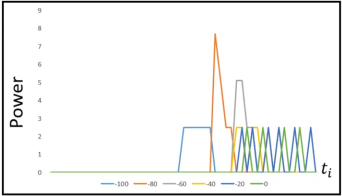
The scan will start from the lowest phase (-100) to the highest phase (0) in a gap of 20 degrees between each phase in a time of *- from 0 to 50 for each phase, decreasing the gap or adding more phases will give us more accurate readings. One scan phase can be interpreted through the projected Table 1 and Figure 5.
Table 1. Power readings with respect to time.
Phase Power For Each Amount Of Time
-100
[0, 0, 0, 0, 0, 0, 0, 0, 0, 0, 0, 0, 0, 0, 0, 0, 0, 0, 0, 0, 0, 0, 0, 0, 0, 2.583463619340189, 2.5864906755903156,
2.5896283049689104, 0, 2.5928442962395457, 2.5960807761738103, 0, 2.5992427224954247, 0, 0, 0, 0, 0, 0, 0, 0, 0, 0, 0, 0, 0, 0, 0, 0, 0, 0]
-80 [0, 0, 0, 0, 0, 0, 0, 0, 0, 0, 0, 0, 0, 0, 0, 0, 0, 0, 0, 0, 0, 0, 0, 0, 0, 0, 0, 0, 0, 0, 0, 7.759582599899415, 5.188925072413356, 2.5992427224954247, 0, 0, 0, 0, 0, 0, 0, 0, 0, 0, 0, 0, 0, 0, 0, 0, 0]
-60 [0, 0, 0, 0, 0, 0, 0, 0, 0, 0, 0, 0, 0, 0, 0, 0, 0, 0, 0, 0, 0, 0, 0, 0, 0, 0, 0, 0, 0, 0, 0, 0, 0, 0, 5.195323498669235, 5.182472601208456, 2.5864906755903156, 2.583463619340189, 0, 0, 0, 0, 0, 0, 0, 0, 0, 0, 0, 0, 0]
-40
[0, 0, 0, 0, 0, 0, 0, 0, 0, 0, 0, 0, 0, 0, 0, 0, 0, 0, 0, 0, 0, 0, 0, 0, 0, 0, 0, 0, 0, 0, 0, 0, 0, 0, 0, 2.5992427224954247,
2.5960807761738103, 0, 2.5928442962395457, 2.5896283049689104, 0, 2.5864906755903156, 0, 2.583463619340189, 0, 0, 0, 0, 0, 0, 0]
-20
[0, 0, 0, 0, 0, 0, 0, 0, 0, 0, 0, 0, 0, 0, 0, 0, 0, 0, 0, 0, 0, 0, 0, 0, 0, 0, 0, 0, 0, 0, 0, 0, 0, 0, 0, 0, 2.5992427224954247, 0, 2.5960807761738103, 0, 0, 2.5928442962395457, 0, 2.5896283049689104, 0, 0, 2.5864906755903156, 0, 0, 2.583463619340189, 0]
Figure 5. Power readings through time as shown in Table 1.
The collected data of power in a certain amount of time on every phase will documented, each phase data sets were analyzed to determine which phase provided or projects the highest intensity power, three loops scan were applied to filter out and determine the highest power intensity. In our proposed method, efficient creation and interpretation of the recordings of time with respect to the location is demonstrated. The corresponding values of L (location) at a given T (Time) on every C (phase) were demonstrated on Table 2.
Table 2. Corresponding values.
Location Z Time [ \] Context C (phase)
' ,.X 1 32 -80
'? ,.X 2 32 -60
'^ ,.X 3 29 -60
'= ,.X 4 26 -60
'` ,.X 5 30 -20
'b ,.X 6 29 -20
' ,.X X X X
5. Conclusion
In this paper, a new approach on predicting the next location were proposed and scrutinized by combining BF with ML technique to generate an automatic location prediction synchronization system. Algorithm composition and simulation of the proposed proposition were run and tested with the aid of python. Systematic and visual interpretation were explored and demonstrated to fully gasp the propounded system design. Supporting theoretical and mathematical calculation were also presented to discerned the algorithm component makeup and validate the system legitimacy. With sufficient theoretical results it was found that BF supported with ML algorithm scheme can be a platform for location prediction application with advantageous characteristics. Such as the elimination of privacy exploitation that is common in next location prediction in the mobile application. Interference reduction
were also addressed by utilizing beamforming since the platform and mode applied enhance the connection with receiver to avoid the noise and fluctuation caused by the environment compared to the one applied in the mobiles, this makes it more effective and efficient in predicting locations. The proposed scheme can be applied on single and multiple users depending on the applications requirement to cater the markets demand.
References
[1] Gomes, João Bártolo, Clifton Phua, and Shonali Krishnaswamy. "Where will you go? mobile data mining for next place prediction." International Conference on Data Warehousing and Knowledge Discovery. Springer, Berlin, Heidelberg, 2013.
[2] Xia, Linyuan, Qiumei Huang, and Dongjin Wu. "Decision Tree-Based Contextual Location Prediction from Mobile Device Logs." Mobile Information Systems 2018 (2018). [3] Barwise, Patrick, and Colin Strong. "Permission‐based
mobile advertising." Journal of interactive Marketing 16.1 (2002): 14-24.
[4] Anagnostopoulos, Theodoros, Christos Anagnostopoulos, and Stathes Hadjiefthymiades. "Mobility prediction based on machine learning." Mobile Data Management (MDM), 2011 12th IEEE International Conference on. Vol. 2. IEEE, 2011. [5] Jaiswal, Ayush, et al. "Location Prediction with Sparse GPS
Data." Proceedings of the 8th International Conference on Geographic Information Science. 2014.
[6] Anagnostopoulos, Theodoros, Christos Anagnostopoulos, and Stathes Hadjiefthymiades. "An adaptive machine learning algorithm for location prediction." International Journal of Wireless Information Networks 18.2 (2011): 88-99.
[7] Wu, Ruizhi, et al. "Location prediction on trajectory data: A review." Big Data Mining and Analytics 1.2 (2018): 108-127. [8] Lu, Zhongqi, et al. "Next place prediction by learning with
[9] Laurila, Juha K., et al. "The mobile data challenge: Big data for mobile computing research." Pervasive Computing. No. EPFL-CONF-192489. 2012.
[10] Yavaş, Gökhan, et al. "A data mining approach for location prediction in mobile environments." Data & Knowledge Engineering 54.2 (2005): 121-146.
[11] Palma, Andrey Tietbohl, et al. "A clustering-based approach for discovering interesting places in trajectories." Proceedings of the 2008 ACM symposium on Applied computing. ACM, 2008. [12] Kalousis, Alexandros. "Predicting the Location of Mobile
Users: A Machine Learning Approach." (2009).
[13] Schreiner, Clint. "Utilizing Digital Down Converter for
Efficient Digital Beamforming." Red River Engineering. [14] Tall, Abdoulaye, Zwi Altman, and Eitan Altman. "Multilevel
beamforming for high data rate communication in 5G networks." arXiv preprint arXiv: 1504.00280 (2015).
[15] Darwish, Mohammad, and Cecil Lau. "A Software Radio Architecture for Smart Antennas." Spectrum Signal Processing, Inc., Vancouver, Canada (1998).