Soil conditions and bounds to suction during the installation of caisson
foundations in sand
Ouahid Harireche
*,Moura
Mehravar,
Amir M. Alani
Department of Ci vi/ Engineering, Medway School of Engineering, Centra/ Avenue, Chatham Mariti me, University of Greenwich, Kent ME4 4TB, UK.
ARTICLE INFO
Keywords:
Caisson foundation lnstallation in sand Normalised geometry Piping condition Failure modes
1. lntroduction
ABSTRACT
Suction installation of caisson foundations is widely adopted in the oil offshore industry. When such foundations are installed in sand. seepage conditions are known to play a pivotal role in the installation process. Pressure gradients generated by the imposed suction inside the caisson cavity cause an overall reduction in the latera! soil pressure acting an the caisson wall as well as in the tip resistance. This transient loosening of sai l around the caisson w ali facilitates ca isso n penetration into the seabed. However. these efTects must be contro !led to avoid sai l failure due to criticai conditions such as piping or loss of sai l shear strength. which may cause the installati an procedure lo fai l due lo instability of the soil plug trapped inside the caisson cavity. In this paper. we endeavour to sntdy these effects based an the analysis of the normalised seepage problem. assuming the installation process to take piace in homogeneous sand. We first investigate the effects of seepage conditions an sai l resistance lo caisson penetration with a particular focus an how frictional resistance and ti p resistance are differently afTected. We then consider modes of failure due tosai l piping inside the caisson cavity an d sliding of sai l mass in a failure mechanism where the sai l plug inside the caisson cavity is pushed upward. Based an this study. some insight is gained into the criticai conditions far piping. These conditions evolve during the installation process as the penetration depth increases under an increasing suction. Upper and lower bounds are also estimated far the criticai suction based an an assumed mode of failure using a simple mechanism of rigid blocks. By comparing these modes of failure we conclude that piping is not always the most criticai conditi an. The criticai mode of failure far a given sai l may change during the installation process and this is highlighted by comparing the criticai suction far piping to the suction upper and lower bounds related to shear failure.
Suction caisson foundations have been ve1y popular in the oil industry and the current trend is to extend their use to the developing industry of wind farms (Byrne et al., 2002; Byrne and Houlsby, 2003). A suction caisson is an upturned 'bucket' of cylind -rical shape made from steel. The thin caisson wall facilitates installation when a pressure differential is induced by suction on the caisson !id, which pushes the caisson to penetrate into the seabed. This is achieved by pumping out the water trapped in the
caisson cavity after initial penetration under self-weight. When such
procedure is used for caisson installation in sand, suction must be
controlled during the whole installation process so that its magni
-tude does not exceed the criticai limit that causes soil failure. !t is
recognised that within the safety limits against soil piping. porewater
seepage induced by suction is beneficiai to caisson installation as it
reduces the overall force that resists caisson penetration (Senper and Auvergne, 1982; "ljelta et al.. 1986; Erbrich and 'ljelta, 1999; Tran et al.. 2004: Tran et al., 2005). CPT tests conducted inside the caisson before and after installation, revealed significant loosening of sand
(Senders and Randolph, 2009).
The role of porewater seepage has been considered in the development of design procedures for the installation of suction
caissons in sand (Tjelta, 1994, 1995; Bye et al.. 1995; Erbrich and Tjelta, 1999; Houlsby and Byrne, 2005). Tran and Randolph (2008)
conducted a series of mode! tests in a geotechnical centrifuge to investigate the variation of suction during the installation of caisson foundations in dense sand. They also performed finite
element simulations to study the criticai hydraulic conditions that develop during caisson installation. Finite element simulations of seepage induced by suction around caisson foundations have also been performed by Zhang et al. (2004). Finite element models with remeshing capabilities have been used to mode! caisson penetration into clay (Vasquez and Tassoulas, 2000; Maniar and Tassoulas, (2002)). Similar simulations have been performed for sand, where soil behaviour has been described with a • Corresponding author. Tel.: +44 1634 883787; fax: +44 1634 883153.
E-mail addresses: [email protected],
Drucker-Prager mode! with ca p (Zeinoddini et al., 2011 ). Ibsen an d Thilsted, (2011 ), used FIAC3D an d performed finite differ-ence simuiations to study piping Iimits to suction, which were applied to fieid installations of suction caissons in sand.
Experimental investigations in dense sand have revealed that soil heave, which is Iikeiy to occur during suction assisted installation, sets an additionai Iimit to suction for the required installation depth to be achieved safeiy (Allersma et al., 1999; Bang et al., 1999; Allersma, 2003; Tran et al., 2004).
Specific soil conditions such as the existence of low perme-ability silt layers that may affect seepage at some stage of the installation process have been considered by Tran et al., (2007). More recently, Harireche et al. (2013) have considered the effects of suction induced seepage during the installation of caisson foundation in sand with permeability varying with depth.
In the aforementioned Iiterature, the hydrauiic gradient on both sides of the caisson wall has been described in terms of an overall vaiue based on the pressure difference between the mud-line and the caisson tip. However, due to the importance of the variation of pressure gradient over the caisson penetration depth, it is important to investigate the gradient distribution over the penetration depth throughout the installation process.
In this paper, we consider the excess porewater pressure gradient in terms of the magnitude of its vertical component at each location within the soil mass. This is motivated by the fact that such component defines the seepage force that acts against gravity and directly affects effective stresses.
In the first part of this study we address the effects of excess pore pressure gradients on soil resistance to caisson penetration. A simple finite eiement procedure is first performed to solve the normalised seepage probiem. The variation in effective stresses on both sides of the caisson wall is calcuiated as a function of the penetration depth an d integrated numerically to provide an estimation of the reduction in magnitude of the penetration resisting forces caused by seepage. Problem dimensions are normaiised so that the results obtained are independent of caisson prototype and apply to any caisson size. Based on the anaiysis of the normalised seepage problem, we derive analytical expressions for the magnitudes by which penetration resisting forces are reduced for a given suction and caisson dimen-sions. The second part of this study is devoted to the investigation of criticai soii conditions during caisson installation. In addition to criticai conditions for piping, a second mode of failure has been investigated, which is based on a shear failure mechanism. This faiiure mode has been motivated by the observed deformation process which consists in soil moving into the caisson cavity. For dense sand, such large deformation process resuits into volume expansion or heave of the soil plug. It is worth examining whether such a deformation process may Iead to soil failure that might become more criticai compared to the piping condition. Based on the finite eiement mode! of the normalised seepage problem, criticai conditions for piping and the assumed failure mechanism can be tracked during the whoie installation process. Upper and Iower bounds to suction have been obtained assuming a simple failure mechanism that consists of two rigid biocks and one singie stress discontinuity. Comparison of these bounds to the criticai suction for piping revealed that the criticai mode of failure may switch from the piping condition to shear failure at some stage of the installation process depending on soii shear strength.
2. Formulation of the normalised seepage problem
We consider the mode! problem of a suction caisson of radius R, height L an d we denote h the depth of caisson penetration into the
seabed. The soil consists of homogeneous sand with permeability k and saturated unit weight Ysat· Fig. 1 shows a vertical section
··
r
- - A
/ c c•
(Domain 01) (Domain{]4)
''
F
G D
(Domainill) (Domainll3)
B
E H
Fig. 1. Normalised geometry.
through the vertical piane of the system caisson-soil where only half of the caisson is represented due to axisymmetric geometry. A cylindrical system with coordinates t" and z* in the meri dian piane is adopted for the normalised problem geometry where ali dimensions are scaled with respect to the caisson radius.
Before caisson installation, water pressure is in hydrostatic condition with an ambient absolute magnitude at depth z,
Po=Pat+rwhw+rwz, where Pat is the atmospheric pressure, Yw the unit weight of water and hw the water height above the mudline. A deviation of the porewater pressure from the hydro-static value at any location within the soil is referred to as excess porewater pressure and is denoted as p. This terminology will be used even in cases where p is negative.
At a certain stage during the caisson installation process, a penetration depth h is reached under the effect of a suction of magnitude 5, assumed constant over the radiai distance oc-(Fig. 1 ). I t is important to note that suction has a negative value; however the magnitude
s
is a positive number. On the mudline boundary c+F outside the caisson, and on the boundaries FH and BH sufficiently far from the zone of significant suction disturbance, the excess porewater pressure p remains zero.The porewater seepage is assumed to obey Darcy's law:
u = - I<Vp where u is the porewater velocity fie! d, k the
perme-ability and Vp denotes the excess porewater pressure gradient. Assuming volume incompressibility of the porewater flow, the constraint divu =O (div= (1jr)ajar+(1jr)ajae+ajaz), must be superimposed onto Darcy's law which, for a homogeneous soil in axisymmetric conditions, results into the well-known Laplace equation:
v2p
=
a2pjar2 +(1jr)apjar+a2pjaz2=o.
As the caisson penetrates into the seabed, radiai porewater flow across the caisson wall is prevented, which is described by the boundary condition o n CD: ap / ar =O an d due t o symmetry, this condition must be satisfied on the z-axis. In arder to obtain the distribution of excess porewater pressure, we divide the soil domain into four regions. Region (!.h) represents soil inside the caisson, (D2) is the region occupied by soil which passes inside the
caisson after further penetration and regions (t:l3) and (t:l4) are the complementary soil regions outside the caisson.
166
procedure of the main problem variables an d we denote:
p*=g
s (1)
the dimensionless counterpart of the excess porewater pressure an d
h z r
h* =
R'
z* =R'
r* = JfO ::;; r* ::;; l on OC an d l ::;; r* < oo on CF) (2)the dimensionless counterparts of the caisson penetration depth and the radiai and vertical coordinates. The excess porewater pressure p* satisfies the dimensionless equation:
.:1 • a2p* 1 ap* a2p*
v
P=
ar•2
+r:;
ar•+
az•2
= 0 (3)and the boundary conditions:
a
p•p*= -1 on oc-, p*= O, on c+F, FH, BH and, - =O on CD and OB
ar•
(4)
The normalised domain in the meridian piane is discretised into four-node bilinear elements. A weak form ofEq. (3) that takes into account the boundary conditions (4) is solved for the unknown excess pore pressure values at nodes. The finite element procedure has the advantage of taking into account soil loosening inside the caisson cavity ( domain D1 ) in a much more natura! way compared
to other numerica! methods. In the following sections, soil loosen-ing inside the caisson cavity is described usloosen-ing a sloosen-ingle constant 1<1 that represents the ratio kdko where ki and k0 are the respective values of sand permeability inside and outside the caisson
(Houlsby and Byrne, 2005). Of particular interest in this analysis
are the effects of suction induced seepage on soil resistance to caisson penetration and soil stability during the installation process. The results of this analysis are reported and discussed in the following sections.
3. Effect of porewater seepage on soil resistance to caisson penetration
Water seepage caused by suction produces a hydraulic gradient which, on both faces of the caisson wall, varies with depth.
Figs. 2a, c and e show the contours of the normalised excess pore pressure p* for values of the scaled penetration depth h* =0.2
(typical of self-weight penetration), h*= l and h* =2. These figures show clearly that the pressure gradient, and hence the velocity
field, has a direction inside the caisson cavity that tends to become
aligned with the z-axis as the penetration depth increases.
Figs. 2b, d an d f show the contours of the vertical component of
the scaled pressure gradient g*
=
ap* ;az*. It can be observed that the highest gradient magnitudes are concentrated around the caisson tip. At shallow penetration depths, high gradients aroundthe caisson wall affect the whole penetration depth. As the penetration depth increases, these gradients tend to localise around the caisson tip.
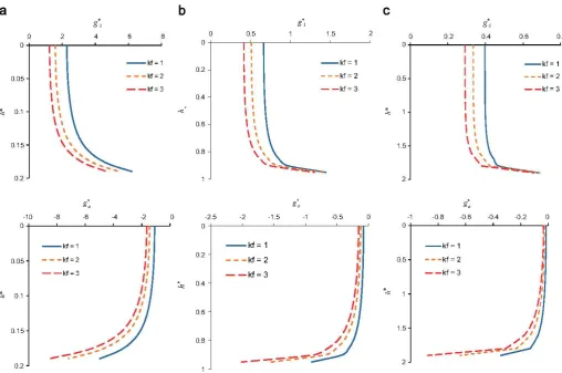
Fig. 3a-c show the vertical component of the normalised pressure gradient g*
=
ap* j az* on both sides of the caisson wallas a function of the scaled depth z* for values of the normalised penetration depth h* =0.2, 1.0 and 2.0. At each of these three normalised penetration depths, the distribution of normalised pressure gradients at each side of the caisson wall is calculated for three values of the permeability ratio, l<f= 1, 2 an d 3.
!t can be seen that the pressure gradient on each side of the caisson wall is higher at early stages of the installation process. Gradient magnitude on the inner side of the caisson wall decreases
as 1<1 is increased, but the apposite trend is observed on the outer
side. Maximum values of the gradient occur at the caisson tip and
the gradient distribution over the caisson embedment tends to become uniform as the penetration depth increases. The effect of 1<1 on the gradient magnitude on the inner si de is no t significant around the caisson tip, but the apposite trend is observed on the outer side.
The pressure gradient inside the caisson cavity has positive values, which indicates upward flow and its magnitude is larger than outside the caisson where seepage flow is downward. This clearly indicates that the upward seepage force generated inside the caisson cavity is larger than the downward seepage force that occurs on the outer side. Such a dissymmetry, which is inherited from the distribution of the pressure gradient, causes more reduction in the effective stress inside the caisson than increase in the same stress on the outer side. This in turn results into an overall reduction in the latera! effective pressure on the caisson wall. As a consequence, frictional soil resistance against caisson penetration is reduced. For similar reasons, the resisting force acting against caisson penetration at the caisson tip is also reduced.
These effects are now investigated in more detail in order to identity the proportions to which seepage affects these resisting forces. In the absence of seepage, when the caisson is pushed into the seabed without disturbing significantly hydraulic conditions, the latera! effective pressure on the caisson wall has the expression:
u/, = K(y'z+ii) (5)
Where K is a latera! earth pressure coefficient. The vertical effective stress near the caisson wall is enhanced by the magnitude
& due to the effect of shear resistance that develops on the interface soil-caisson. The latera! pressure coefficient !( has gen-erally a larger value compared to the latera! pressure coefficient at rest.
Under seepage conditions produced by an applied suction, the latera! effective pressure acting on the caisson wall, at depth z, inside and outside the caisson is respectively expressed as follows:
uh';(R,z)=K(r'z-
iz
g;(R,0d(+&;(R,z)) (6)"h~(R,
z)=K(r'z-
foz
g0(R,0d(+&o(R,z)) (7)Where g;(R, 0 and g0(R, 0 denote the vertical component of the pressure gradient on the inner and the outer sides of the caisson
wall respectively. If we assume that the enhanced effective stresses &; and &0 are not affected by seepage conditions, then the reduction at depth z in the latera! pressure acting on the
caisson wall, caused by seepage, is given by
(8)
The pressure gradients can be expressed as follows:
(9)
Where gl)
=
ap* j az* is the normalised pressure gradient in domains (D4 ), (D3 ) and gj=
ap* ;az* denotes the same quantitywhen evaluated in domains (D1 ) and (D2 ). Hence, expression (8)
can be rewritten under the following form:
flui, (R,z)
Ks
Where, as can be observed from Fig. 3:
L~Cz*)
=
foz•
gr
(l, ç*)dç* >o,
r:cz*)=
fo
z*
g6(1,ç*)dç*<
o
and ILr(z*)l > IL6(z*)l(lO)
a
b
o o o
4
-0.2 -0.2 ·0.2
2
-0.4 -0.4 -0.4
o
-0.6 -0.6 -0.6
·l
-0.8 -0.8 -0.8 -2
-3
·l -1 ·l
o 0.5 1.5 2 2.5 3 o 0.5 1.5 2 2.5
c
d
o o o 1.5
-0.5 -0.5
-0.2
-l -l
·1.5 -0.4 ·1.5 0.5
-2 -2
-0.6 -2.5 o
-2.5
-3 -3
-0.8 ·0.5
-3.5 -3.5
-4 -l -4 -l
o 0.5 1.5 2.5 3 o 0.5 1.5 2 2.5 3
e
f
o o o
0.8
·l -l
-0.2
0.6
-2 -2
-0.4 0.4
-3 -3
0.2
-0.6
-4 -4 o
-0.8 -0.2
-5 -5
-0.4
-l -6
0.5 1.5 2 2.5 3 o 0.5 1.5 2 2.5 3
168
a
b
c
o 2 4 6 8 o 0.5 1.5 2 0.2 0.4 0.6 0.8
0+---rr~----._ ____ ._ __ ~ 0+---.-r-,---~---L----~
o
0+---~--.-~+---~---~
--kf~1
0.2
0.05 ---kf~2
--kf~3
0.4
~ 0.1
0.6
0.15
0.8
0.2
-8 -6 -4 ·2 o -2.5
l l l l l
l
'
'
l
l
~
l
'
\
~
\
,
\
,
- -kf= 1
- - -kf=2
- - kf= 3
'
~
-
---·2 -1.5 -1 -0.5
0.5
1.5
2
o -1 -0.8
l
l
l
l
l
l
l
\ l
\
,
\
,
-0.6
- - -kf= 1
- - -kf= 2
- -kf= 3
-0.4 -0.2 o
-10
0+---~----~--~----~nr_J o+---'---'---'---j__--....r' 0+---~----~----L----L--_,r
0.2 0.05
':..:! 0.4 ~ 0.1
0.6
0.15
0.8
0.2
- -kf= 1
- - -kf=2
- - kf= 3
.
""0.5
1.5
2
Fig. 3. Dimensionless pressure gradient as a function of scale d depth far different. caisson penetration depths: (a) h*~ 0.2, (b) h*~ 1.0. (c) h*~ 2.0.
Using a numerical calculation of the integrals in (11) an the
normalised finite element mesh, we obtain the normalised
reduc-tion of the lateral effective stress expressed in ( 10) as a function of
the normalised depth z*. As a consequence, seepage causes the
frictional resisting force acting an the caisson wall to decrease by a
magnitude M5 given as a function of the normalised penetration
depth h* by the expression:
h*
la
[L7(z*
)
+L~(z*
)
]dz*
(12)Where 8 denotes the angle of friction a t the interface soil-caisson.
lt is important to note that an the inner face of the caisson wall,
upward seepage causes a loosening of the soil, which in turn
reduces the angle of internai friction rj;' and increases the lateral
pressure coefficient K. A more accurate expression of .1F5 would be
obtained if these effects are accounted far. In the present work, soil
loosening is reflected qualitatively in the coefficient 1<1 introduced
earlier and will be considered with more developments at the end
of this section where comparison will be made with some
experimental data.
Seepage also causes the vertical effective stress at the caisson
tip to decrease, thereby leading to a further reduction in the total
resisting force. The resisting force at the caisson tip can be
expressed under the form:
ft = 2:n:RNq {R.
u~
drjRi (13)
where Nq is a bearing capacity factor and "~ the vertical effective
stress a t the caisson tip, which is assumed t o vary linearly from cr,;;
inside the caisson (radius R1) to uv~ outside (radius R0 ), and these
stresses have the expressions:
crv';(R,h)=y'h-
!ah
g;(R,()d(+ii;(R,h). rh
crv~(R,h)=yh-Jo g0(R,()d(+ii0(R,h)
(14)
(15)
Assuming that seepage does not affect the enhanced vertical stress, the resisting force at the caisson tip decreases by the
magnitude Mt such that:
~=~(L
*
(h*
)
+L
*
(h*
))
2:n:RtNq5 2 1 0 (16)
Where functions L7(z*) an d L~(z*) are defined by expressions (11 ).
Expression (16) assumes a linear distribution of the vertical
effective stress at the caisson tip through the thickness t of the
caisson wall.
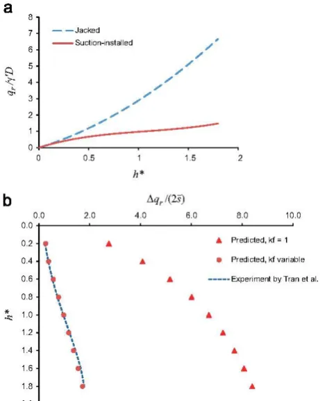
The predictions of the reduction in soil resistance due to
suction induced seepage expressed by Eqs. (12) an d ( 16) are now
compared to the experimental results obtained by Tran and Randolph (2008) (Fig. 4a). These experiments have been
per-formed in a centrifuge an a caisson model made from aluminium,
60 mm in diameter, 60 mm in length and 0.3 mm in wall
thick-ness. The curve corresponding t o jacked installati an, in Fig. 4a, has
been used to identify values far the parameters Ktan(o) and Nq of
1.02 and 187, respectively. In Fig. 4a, qr denotes the penetration
resistance which is the ratio of the total penetrati an resisting force
aver the horizontal cross-sectional area of the caisson.
a
b
..
-<: 5 4 2 0.0 0.2 0.4 0.6 0.8 1.0 1.2 1.4 1.6 1.82.0
- -Jacked --Suctton~nstalled
0.5
h*
0.0 2.0 4.0
•
l"
l
•
l...
l
"
ll
"
ll 41 l
l ~.
.
~
•
..
l•
•
1.5 2
Aq,l(2s)
6.0 8.0 10.0
...
Predicted, kf"' 1•
Predtcted, kfvariable...
---Experiment by Tra n et al."
...
...
"
"
...
Fig. 4. (a) Experimental data Tran and Randolph (2008). (b) Validation ofpredicted
reduction in penetration resistance for suction-installed caisson.
shown in Fig. 4b, where the experimental data are represented
with a discontinuous line. It can be observed that these
experi-mental data do no t fit t o the theoretical prediction when the effect of soil loosening inside the caisson cavity is not taken into
consideration. This is the case kt= 1 in Fig. 4b. l t is important to note that the discrepancy between experimental data and pre-dicted results increases with the normalised depth, suggesting
that, no t only 1<1 should be larger than unity, it must also increase
during the installation process to reflect continuous soilloosening
as suction increases.
Indeed, further testing with values of 1<1 larger than unity but constant throughout the installation process led to the same conclusion. Hence, the permeability factor 1<1 must be variable during installation and must be an increasing function of the normalised penetration depth h*. We assume the following simple
linear expression:
(17)
After few trials with the simulation of seepage at the first depth increments, values of the parameters a and l<jv have been identi-fied as 3.0 and 1.3, respectively. The value 1.3 must be interpreted
as the permeability ratio when suction is first applied at very shallow penetration depth, after self-weight penetration. It can be observed from the predicted results corresponding to a variable coefficient 1<1 in Fig. 4b that in this case, the simulations fit very
well to the experimental predictions for the whole installation
process. This comparison with experimental data highlights clearly the importance of soil loosening inside the caisson cavity as a result of suction induced seepage during the whole installation
process. Expression (17) provides a simple description of the parameter lqwhich has been adopted in this study to qualitatively reflect such loosening effects. While this validation exercise hig
h-lighted the pertinence of the simple assumed form ( 17) of the
parameter kJ. further experiments are required to justifY whether
the parameters a and kJD are constants, inherent to the normalised geometry of the caisson problem or dependant on other parameters.
4. Bounds to suction
4.1. Critica/ suction for piping condition
We define the maximum suction for piping Smax as the suction that causes the volume of soil inside the caisson cavity to develop piping condition. The suction magnitude that may cause failure of the soil plug should only be a fraction of the maximum value an d we refer to it as critica/ suction. At a generic material point of normalised coordinates r*, z* within the soil inside the caisson, piping takes piace when the vertical effective stress becomes zero. This is expressed by the equation:
"~
= y'z-[ g;(R, ()dr;= O (18)Hence, the suction magnitude that causes such condition is given by:
s
z*y' R = Lj(r*, z*) (19)
where
t;'Cr*, z*)
=
fo"'
gj(r*, r;*)dç*Houlsby and Byrne (2005) have proposed the piping criterion:
s
f
(r'R)
=h*/(1-a) where a is the magnitude of the normalised pressure a t the caisson ti p on the inner si de; i.e. a= -p*(h*). Theproposed criterion assumes a constant pressure gradient on each side of the caisson wall. In the present study, based on the numerical solution for the normalised seepage problem, condition (19) is an expression of the same criterion that takes into account the actual variation of the pressure gradient as a function of depth.
The minimum suction that causes piping condition, which first appears at the caisson tip on the inner side, is given by (19) for
z*=h* an dr*= 1, i. e., 5/(r'R) =(h* /L;*(h*)). Hence, to account for the
variation of the pressure gradient on the caisson wall, the coefficient a used by Houlsby and Byrne (2005) is to be replaced
by the coefficient (1- Lj(h*)). Fig. 5 shows a comparison of
parameters a and (1-L*). The difference between these two parameters does not seem to be affected by penetration depth
•parameter a (Houlsby and Byrne), kf~ 1 <>(H'),kf~1
"parameter a (Houlsby an d Byrne, kf ~ 2 6.(H'),kf~2
eparameter a (Houlsby and Byrne), kf~ 5 o(H'),kf~5 0.8
0.7 i o
•
o•
o0.6
•
o>:""
•
o";l
...
•
o0 0.5
..
4•
o•
o"d
...
...
•
o§
•
~ <>
..
4~ 0.4
•
..
...
"'
<>..
4.'l
•
<>...
...
...
~
0.3 <>..
...
4•
..
:;;
•
<>.. ..
<> o.
0.2
•
•
<> <> <>• •
<>• •
0.10.0
o 0.2 0.4 0.6 0.8 1.2 h!D
170
1.0
0.8
0.6
0.4
0.2
- -h'; 0.2, kf; 1
- -h'; 0.2, kf; 2
----·h'; 0.2, kf; 3
- -h'; 2.0, kf; 1
- -h'; 2.0, kf; 2
,l
:l
!l
IJ
,
O .O -J--...o~~Z:::....___,.---r---""""'!!!!j'!!!!!!::.----,
0.0 0.2 0.4 0.6 0.8 1.0
S/Smax
Fig. 6. Proportion of soil volume subject to piping condition as a function of the fraction of maximum suction.
and is not significantly affected by the parameter kf The magni-tude of this difference being relatively small, may justity the use of parameter a, which is simpler to calculate and conservative as far
as piping condition is concerned.
In arder to qualitatively estimate the criticai suction that causes
failure of the sai! plug due to piping conditi an, we investigate the
relationship between the suction ratio sfsmax and the ratio V9fV of
the volume of sai! that develops piping t o the total volume of sai!
inside the caisson cavity. Fig. 6 displays such relationship far
different values of the scaled penetration depth. Curves in Fig. 6
are plotted to the resolution of the finite element mesh, by checking conditi an ( 19) far each element.
!t can be seen that the suction magnitude that causes sai!
piping to initiate inside the caisson cavity is a higher fraction of
the maximum suction as the penetration depth increases. This means that at larger penetration depths, a moderate increase in the suction ratio sfsmax is likely to become criticai, compared to
similar scenarios at earlier stages of the installation process. Fig. 6
shows clearly how the suction ratio curves become steeper far larger penetration depths, which indicates that the criticai suction
magnitude becomes closer to the maximum suction as the penetration depth increases.
4.2. Upper bound
4.2.1. Failure mechanism and compatibility conditions
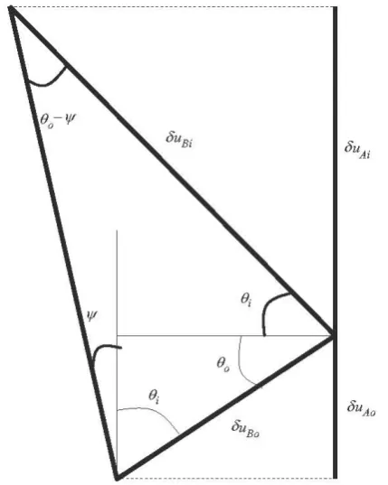
In the assumed failure mechanism (Fig. 7), the rigid blocks B0
an d Bi are subject t o displacement increments of magnitudes c5u80
and c5u8i respectively. Their directions have inclination angles 00
and O; to the horizontal, respectively (Fig. 8). These angles have the
expressions:
(20)
Where IJI is the sai! dilation angle. Blocks Ao and Ai are subject to
vertical increments of displacement denoted c5uAo and c5uA;, respec
-tively. Compatibility conditions (no separation or interpenetration
of blocks) impose the following relations on these displacement
(A() (A.)
~rr
T
~----~~~~+----~.JK,
Fig. 7. Assumed failure mechanism and stress discontinuity for the calculation of suction bounds (normalised geometry).
Fig. 8. Compatible displacement increments in the assumed failure mechanism
increments:
DUAo DUA,. DUA,.
c5u Bo = COS (),·' c5u BI · - - - -- () and --=~ o .,
COS 0 uUAo
tan (O; +IJI) tan 00
(21)
The variation of external work c5fe in these increments of dis-placement is given by:
(22)
Where W~ denotes the magnitude of the effective gravity force acting on sai! volume D0 outside the caisson (volumes Ao and Bo)
a
2
~
1.0
0.8
§
0.6·~ ~ ] 0.4
l
0.2- -lowerbound ---6--upperbound
----· 1% pipin g - - 1 O% pipin g
e 8 e e 8 e
e
~uo
dB
•••~
.---·
0.0 + - - - - . - - - . - - - . . - - - - r - - - - r - - - - .
18 20 22 24 26
Friction angle (')
c
3.1
2
2.8~
:!l 2.5 .9
~
] 2.2~
i
1.928 30
~lower bound
----·1% piping
20 22
b
21.75
~
~ 1.5
:!l
.1
;;: 1.25"d
1i ~
§
o
z
0.75
0.5
24
~lowerbound ~upperbound
----·1% piping - - 10% piping
18 20
~upper bound
- -10% piping
26 28
22 24
Friction angle (')
30
26 28 30
Friction angle (')
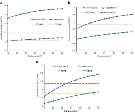
Fig. 9. Upper and lower bounds ofnormalised suction as functions ofthe angle ofinternal frictionfordifferentvalues ofthe scaled penetration depth: (a) h*=0.2, (b) h*= 1.0,
(c) h*=2.0.
magnitudes have the expressions:
(23)
Pressure gradients g0 and g; in (23) have the expressions (9) in
terms of normalised gradients. Using these expressions, the integrais invoived in (23) can be rewritten as follows:
1
g0 dV=2nR
2s(l~
+
J~)
an d1
g;dV = 2nR2
s(lr
+
;r)
Qo .Qi(24)
Where
-1h.],1+Ko -1h·+~
1
1+Ko-(z>-h')~ *~ = ~r*dr*dz*,
ro
= ~r*dr*dzQ 1 h... 1
(25)
!o
h*il
l
h*+.JKo
11
J7
=
g/'r*dr*dz*,Jr
=
g/'r*dr*dz*O O h* (z•-h*)j.y'Ko
(26)
The voiumes D0 and D; have the expressions:
(27)
(28)
Suction UP,per bound Su is calcuiated assuming associated piasti-city, i. e., <f; = lf, which ieads to a zero-variati an in internai work
(see far instance Atkinson (1993)). Hence, the expression of the theorem of virtuai work reduces to the equation:
òEe = W~òv0-w;sv; =O (29)
After substituting the expressions (23) of
w:
andw;
into (29),taking into account (24) and the compatibility conditions (21), we obtain:
Su Do-,;D;
r'
R-2n~ [(!~+]~)-W~+]~)] (30)Note that under the assumption of associate piasticity, the assumed failure mechanism is valid far vaiues of the angie of internai friction <f;' not exceeding 30°. However, this iimitation is not very restrictive in the present study as the purpose of this investigati an is to show the reievance of the shear failure mechan-ism, which is iikeiy to be justified far moderate faiiure angies, especially due to sai! ioosening under suction an the inner side of the caisson.
Fig. 9 shows the variation of the normalised suction upper
bound as a function of the angie of internai friction cf! far different
172
4.3. Lower bound
We select the cylinder of unit radius in the normalised geometry as single stress discontinuity (Fig. 7). The lower bound theorem, which states that the failure criterion should not be violated anywhere within each of the zones separated by the stress discontinuity, where the stress field satisfies equilibrium (Atkinson, 1993), is governed by the state of stress at points A and B at the caisson tip (Fig. 7). The three stresses (u~)A, (u~)s and uì,, at the caisson tip, denote the vertical effective stresses at points A and B and the latera! effective stress acting on the discontinuity surface, which remains continuous due to equilibrium. These stresses have the expressions
h h'
(a{)A=
1
(r'-g0(R,z))dz=1
(r'-~(l,r))Rdz*=Rr'h*-sL~(h*)
(31)
h ~
-(o-{)8=
1
(r'-g;(R,z))dz=1
(r'-~(l,z""))Rdz*=Rr'h*-sLj(h*)
(32)
uj,
= Ko(u{ )A= -}:.u; )B (33)Eq. (33) holds when sai! yields on both sides of the stress discontinuity and points A and B are in active and passive states respectively. The functions L~(z*) and L;*(z*) are given by
expres-sions (11).
By substituting (31) and (32) into (33) we obtain an expression far the suction lower bound based on the assumed stress dis-continuity:
51 h*(1- K02)
r'R = L7Ch*)-Ko2L~(h*) (34)
Fig. 9 shows the normalised suction lower bound as a function of
the soil internai angle of friction <f;' far different values of the normalised penetration depth h*.
Fig. 9 also displays the normalised suction magnitudes that correspond to 1% and 10% of the soil plug volume affected by the piping condition. lt can be seen that as the penetration depth increases, shear strength tends to govern soil stability. Far instance, at a normalised depth h*=2 (Fig. 9c), the suction ratio that causes 10% of soil piping exceeds the suction upper bound far a range of friction angle values up to 23°. This shows clearly that, while piping governs the criticai soil condition during the early
stages of caisson installation, such condition may switch to a
failure mechanism governed by shear strength at larger penetra-tion depths. Hence, both mechanisms must be considered when estimating a safe suction profile far caisson installation in sand.
This justifies the need far further investigation regarding the modes of soil failure during caisson installation in sand.
5. Condusion
This investigation has been motivated by the need to develop rational procedures to predict the effects of suction-induced
seepage on sai! conditions during caisson installation in sand.
The numerica! solution of the normalised mode! problem far seepage around a caisson foundation has first been obtained. Normalised pressure gradients have been used to study sai! resistance to caisson penetration and criticai conditions far soil
failure. The present analysis takes into account the actual variation
in pressure gradient on both sides of the caisson wall.
Expressions far the magnitudes by which penetration resisting
forces reduce due to seepage have been derived. These expressions
can be evaluated at different penetration depths with the help of the numerica! solution of the normalised seepage problem. Criticai conditions far sai! piping have been investigated in conjunction with a second shear failure mode affecting the soil plug. Piping is found to govern the criticai failure condition at the early stages of the installation process. The failure criterion might switch to a mechanism governed by shear failure at larger penetration depths far sufficiently low shear strength. These findings justity the need far further investigati an of the m od es of soil failure during caisson installation in sand. Extension of the present work may consist in considering more appropriate failure mechanisms and stress discontinuities to overcome the limitation on the sai! angle of internai friction set by the simple mechanism adopted in this work Finally, the effect of low permeability layers, such as the existence of day substratum within the installation depth, may be considered as it is expected to affect the criticai installation conditions described in this paper.
Acknowledgement
Funding of a PhD scholarship by the University of Greenwich to support the second author is gratefully acknowledged.
References
Allersma, H.G.B., Kirstein, A.A.RB., Brinkgreve, T.S., 1999. Centrifuge and numerica! modelling of laterally loaded suction piles. In: Proceedings of the Ninth lnternational Offshore and Polar Engineering Conference. Brest, France, vol. 1, pp. 711-717.
Allersma, H. G. B., 2003. Centrifuge research on suction piles: installation and bearing capacity. In: Proceedings BGA International Conference on Founda -tions: Innovations, Observations, Design and Practice. Dundee, UK, pp. 91-98.
Atkinson, J.H., 1993. An Introduction to the Mechanics of Soils and Foundations: Through Criticai State Soil Mechanics. McGraw Hill International Series in Civil Engineering, UK p. 360.
Bang, S., Cho, Y., Preber, T., Thomason, J., 1999. Mode! testing and calibration of suction pile installation in sand. In: Proceedings of the 11th Asian Regional Conference on Soil Mechanics and Geotechnical Engineering. Seoul, Korea, pp. 235-256.
Bye, A., Erbrich, C. T., Rognlien, B., Tjelta, T. 1., 1995. Geotechnical design of bucket foundations. Offshore Technology Conference. Paper OTC 7793. Houston, TX, 16pp.
Byrne, B. W., Houlsby, G.T., Martin, C., Fish, P., 2002. Suction caisson foundations for offshore wind turbines. Wind Eng. 26 (3), 145-155.
Byrne, B.W., Houlsby, G.T., 2003. Foundations for offshore wind turbines. Philos. Trans. R Soc. London Se r. A 361, 2909-2930.
Erbrich, C.T., Tjelta, T.l., 1999. Installation of Bucket Foundations and Suction Caissons in Sand: Geotechnical Performance. Offshore Technology Conference. Paper OTC Houston, TX 10990, 11pp.
Harireche, O., Mehravar, M., Alani, A.M., 2013. Suction caisson installation in sand with isotropic permeability varying with depth. Applied Ocean Research 43, 256-263.
Houlsby, G.T., Byrne, B.W., 2005. Design Procedures for lnstallation of Suction Caissons in Sand. In: Proceedings of the lnstitution of Ovil Engineers, Geo-technical Engineering. 158(3), pp. 135-144.
Ibsen, LB., Thilsted, C.L, 2011. Numerica! study of piping limits for suction installation of offshore skirted foundations and anchors in layered sand. In: Taylor, Group, Francis (Eds.), Frontiers in Offshore Geotechnics Il- Gouvernec & White, London, ISBN: 978-0-415-58480-7.
Maniar, D. R., Tassoulas, J. L, 2002. Non-linear finite element simulation of suction caissons. In: Proceedings of the 15th ASCE Engineering Mechanics Conference, 2-5 June 2002. Columbia University, New York.
Senders, M., Randolph, M.F., 2009. CPT-based method for the installation of suction caissons in sandJournal of Geotechnical and Geoenvironmental Engineerin
-gASCE, pp. 14-25.
Senper, D., Auvergne, G.A, 1982. Suction anchor piles-a proven alternative to driving or drilling. Offshore Technology Conference. Houston, USA. OTC 4206. Tjelta, T.l., Guttormsen, T.R, Hermstad, J., 1986. l.arge-scale penetration test at a
deepwater si te. Offshore Technology Conference, Paper OTC 5103. Houston, TX, 12pp.
Tjelta, T.l., 1994. Geotechnical aspects of bucket foundations replacing piles for the Europipe 16/11-E Jacket Offshore Technology Conference. Paper OTC 7379, Houston, TX, 10pp.
Iran, M. N., Randolph, M. F. Airey, D. W., 2004. Experimental study of suction installation of caissons in dense sand. In: Proceedings ofthe 23rd lnternational Conference on Offshore Mechanics and Arctic Engineering. Vancouver, Canada, Paper number: OMAE04-51076.
Iran, M. N., Randolph, M. F., Airey, D. W., 2005. Study of seepage flow and sand plug loosening in installation of suction caissons in sand. In: Proceedings of the 15th lnternational Offshore and Polar Engineering Conference, 19-24 ]une, 2005. Seoul, South Korea, pp. 516-521
Iran, M.N., Randolph, M.F., Airey, D.W., 2007. lnstallation of suction caissons in sand with silt layers.]. Geotech. Geoenviron. Eng. 133 (10), 1183-1191.
Iran, M.N., Randolph, M.F., 2008. Variation of suction pressure during caisson installation in sand. Géotechnique 58 ( 1 ), 1-11.
Vasquez, L F., Iassoulas, ]. L, 2000. Finite element analysis of suction piles. In: Proceedings of the European Congress on Computational Methods in Applied Sciences and Engineering, Barcelona, 11-14 September 2000.
Zhang, s., Zheng, Q, Liu, X., 2004. Finite element analysis of suction penetration seepage field ofbucket foundation platform with application to offshore oilfield development. Ocean Eng. 31, 1591-1599.
Zeinoddini, M., Mousavi, S. A., Abdi. M. R, 2011. Simulation of suction caisson