DESIGN AND MODAL ANALYSIS OF
COMPOSITE DRIVE SHAFT FOR
AUTOMOTIVE APPLICATION
Mohammad Reza Khoshravan
Faculty of Mechanical Engineering, University of Tabriz Tabriz, 51666-16471, Iran
Amin Paykani
Faculty of Mechanical Engineering, University of Tabriz Tabriz, 51666-16471, Iran
Aidin Akbarzadeh
Faculty of Mechanical Engineering, University of Tabriz Tabriz, 51666-16471, Iran
Abstract:
This paper presents design method and vibrational analysis of composite propeller shafts. A propeller shaft is not limited to vehicles, but in many transmission applications can be used, but in this paper, the aim is to replace a metallic drive shaft by a two-piece composite drive shaft. Designing of a composite drive shaft is divided in two main sections: design of the composite shaft and design of couplings. In composite shaft design some parameters such as critical speed, static torque and adhesive joints are studied; the behavior of materials is considered nonlinear isotropic for adhesive, linear isotropic for metal and orthotropic for composite shaft. Along with the design all the analyses are performed using finite element software (ANSYS). The results show significant points about optimum design of composite drive shafts.
Keywords: drive shaft; composite; natural frequency; modal analysis. 1. Introduction
algorithm and ANSYS. They found that the use of composite materials lead to the significant reduction in weight compared to steel drive shaft. They also reported that the fiber orientation of a composite shaft strongly affects the buckling torque. Rastogi [4] implemented a FEA approach to design and analyze a composite drive shaft in different conditions.
In the present work an effort has been made to design a HM-Carbon/Epoxy composite drive shaft. A one-piece composite drive shaft for rear wheel drive automotive application is designed and analyzed using ANSYS software. Since performance of conventional drive shafts can be severely limited by the critical speed and large mass inertia moment of metal shaft, it was investigated in the second part of the paper.
Figure 1. Photographic view of a two-piece steel and one-piece composite drive shaft [2]
2. Design of composite drive shaft
2.1 specification of the problem
The torque transmission capability of the drive shaft is taken as 3000 N.m, the length and the outer diameter here are considered as 2 meters and 120 millimeters, respectively. The drive shaft of transmission system was designed optimally to meet the specified design requirements.
2.2 Assumptions
The shaft rotates at a constant speed about its longitudinal axis. The shaft has a uniform, circular cross section. The shaft is perfectly balanced, all damping and nonlinear effects are excluded. The stress-strain relationship for composite material is linear and elastic; hence, Hook’s law is applicable for composite materials. Since lamina is thin and no out-of-plane loads are applied, it is considered as under the plane stress.
2.3 Selection of Cross-Section and Materials
The HM Carbon/Epoxy material with fiber volume of 60% is selected for composite drive shaft. The factor of safety is taken as 6. Table 1 shows the mechanical properties of each layer of the laminate.
2.4 Calculations
Table 1. Mechanical properties for each lamina of the laminate
Property HM Carbon/Epoxy
)
(
11
Gpa
E
190)
(
22
Gpa
E
7.7)
(
12
Gpa
G
4.212
0.3)
(
1
1
Mpa
c
t
870)
(
2 2
Mpa
c
t
540)
(
12
Mpa
30)
/
(
kg
m
3
1600f
V
0.6By using Hill theory, it would be possible to calculate the dimension for failure. With the thickness of 2.03 millimeters and the applied loads, the 0
0 fibers will not be ruptured. With the thickness of 2.2 millimeters and the applied loads, the 0
90 fibers will not be ruptured. Due to the torsion of the shaft, the buckling is negligible.
(1)
3. Modal analysis of composite drive shaft
3.1. Critical speed analysis in composite drive shafts
The main point that attracts manufacturers to use composite materials in the drive shafts is that they make it possible to increase the length of the shaft.The relationship between shaft's length and the critical speed for both types of drive shafts are shown in Figure 2. It is evident that for a specific application where the critical speed is about 8000 rev/min, the longest possible steel shaft is 1250 mm, while the composite one can have a length 1650 mm [2].
Figure 2. The effect of shaft length on critical speed [2]
Critical speed of a shaft is obtained through following equation:
2 2 2
2 2
l t t l lt
lr tr lr ltr
Where Ncris the critical speed and f is the bending frequency. Considering that the natural frequency of a shaft according to the above equation is inversely proportional to the square of shaft's length and is proportional to the square root of Young's module, conventional steel drive shafts are made of two pieces to increase the natural frequency of the shaft, which results in overall increase in weight of shaft. So, in order to increase the natural frequency, the length of shaft should be reduced or E/ratio should be increased. Despite the space limitations that confines outer diameter of the shaft, the only way to increase the critical speed is to increase E/ratio (Specific module) [3].
One of the interesting properties of metals is that although there is a clear difference in their density, their specific modulus is almost constant. With applying fiber-reinforced composites, fiber orientation arrangement becomes possible in the shaft; therefore, bending modulus will be high. Also their relative density is low leading to the desirable specific modulus and increases the critical speed [5].
The natural frequency of the shaft was obtained through Timoshenko theory as following equation:
2 2 2
30 2
nt s
p Er
f K
L
(3)
Wherefntis the natural frequency, p is the first natural frequency and
,Eare properties of the steel shaft. Ksis given by following equation:2 2 2
2 2
1
1 1
2
s s
f E
p r
K L G
(4)
Where the G is modulus of rigidity of steel shaft and
f
s is equal to 2 for hollow cross sections. Then critical speed is obtained in following way [3]:Ncr60fnt (5)
3.2. Modal analysis of composite drive shaft using ANSYS
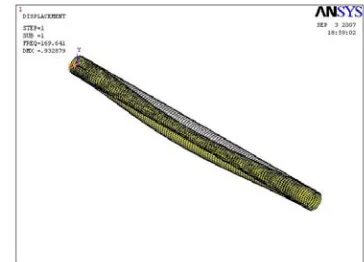
In this study, finite element analysis is conducted using ANSYS software. To model the composite drive shaft Shell 99 element is used and it is subjected to torque. The shaft is fixed at both ends and is subjected to torque at the middle. Figure 3 shows the domain of finite element mesh. Once the finite element mesh and the layers are created, orientation of materials is defined for the shell element and layer materials for each of these elements are being allocated. The other steps include placing the boundary conditions and selecting appropriate solvers. The shaft rotates with maximum speed so the design should include a critical frequency. If the shaft rotates at its natural frequency, it can be severely vibrated or even collapsed. The modal analysis is performed to find the natural frequencies in lateral directions. The mode shapes for all material combinations are obtained to their corresponding critical speeds. A number of fundamental modes, which all are critical frequencies, are obtained. If the shaft's frequencies correspond to these ones, it may be collapsed.
The dynamic analysis shows that the first natural frequency is 169.64 Hz, and according to it the critical speed is equal to 10178 rpm, which is much more than the critical rotational speed of 4000 rpm. According to the equations obtained in previous section, natural frequency of a specific composite drive shaft is 4570.2 rpm. This value is very different from the initial value because the correlations used to obtain the values associated with the shaft, were in case of considering some assumptions.
Figure 3. The mesh configuration of composite shaft Figure 4. The deformation form of composite shaft at first mode
Figure 5. The displacement rate of composite shaft Figure 6. The displacement rate of composite shaft
in x-direction at first mode in y-direction atfirst mode
Figure 7. The displacement rate of composite shaft Figure 8. The total displacement contour of composite shaft at in z-direction at first mode first mode
Table 2. Natural frequencies of composite drive shaft
Frequency Number
Frequency (Hz)
1 169.64
2 182.67
3 226.73
4. Design of adhesive joints in composite drive shafts
The joints used for connecting composite materials can be metallic or non-metallic. Steel fasteners due to the possibility of galvanic corrosion with carbon-epoxy materials, are mainly made of titanium or stainless steel. Other alloys such as aluminum or steel can be used provided that no contact with the surface is occurred.Joints are divided to metal screws and rivets. Non-metallic connectors are created from reinforced thermo set or thermoplastic resins. By using this connection, structural weight reduces and corrosion problems disappear [6]. In this part, firstly the thickness of the adhesive and length of adhesive bond are computed. Then, a finite element analysis of this type of bond is performed using ANSYS software.
The "Araldite" adhesive was used in this study. The following correlations were used to calculate the required parameters:
max
2 tanh
2
m
c c
a a
G l a
Gee
(6)
Where l is the length of adhesive bond. For obtaining reasonable results the only possible way is to increase the value of e. so, the thickness of the adhesive and the length of the adhesive bond are obtained 12 millimeters and 4.5 centimeters, respectively. The details of the bond are given in Table 3.
Table 3. Mechanical properties of the adhesive
Property Value
E
2.5 GpaG
1 Gpac
e
0.25l
45 mmLayers orientation
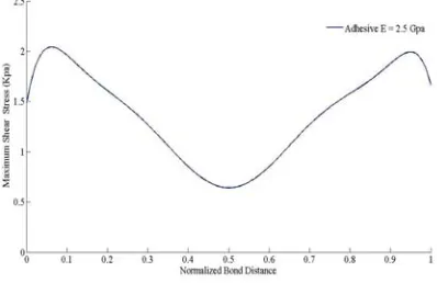
For analysis, a FE model was applied using the 3 - D linear solid elements. A suitable mesh for finite element modeling of adhesive layer is needed. The shear distribution stress of the adhesive is shown in Figure 9. Application of appropriate adhesive, results in decreased maximum shear stresse in adhesive at the edges of the connection; however, if the stresses remain same in the middle connection, start of failure will depend on the relative shear strength values in the adhesive.
Figure 9. Shear stress distribution in the adhesive bond connection 6
5. The weight comparison between composite and steel drive shafts
The entire of vehicle drive shaft is consisted of several rotating masses. About 17-22% of the power generated by the engine is wasted due to rotating mass of power train system. Power is lost because a lot of energy is needed to rotate heavy parts. This energy loss can be reduced by decreasing the amount of rotating mass. Table 4 represents the comparison of inertia moment between composite and steel drive shafts.
Table 4. Comparison of inertia moment between composite and steel drive shafts 2
(
.
)
m
I
Kg mm
4
(
)
I mm
18370.9
6
0.57 10
Steel
9945
6
1.59 10
Composite
45.8%
64.1%
%
Diffrence
In Figures 10, a mass comparison between steel and composite drive shafts has been done.
Figure 10. Mass comparison between steel and composite shaft
6. Conclusion
In this paper a one-piece composite drive shaft is considered to be replaced a two-piece steel drive shaft. Its design procedure is studied and along with finite element analysis some important parameter are obtained. The composite drive shaft made up of high modulus carbon / epoxy multilayered composites has been designed. The replacement of composite materials has resulted in considerable amount of weight reduction about 72% when compared to conventional steel shaft. Also, the results reveal that the orientation of fibers has great influence on the dynamic characteristics of the composite shafts.
References
[1] Gay, D.; V. Hoa, S.; W. Tsai, S. (2004). Composite materials: design and application, CRC press. [2] Pollard, A.; (1999): Polymer matrix composite in drive line applications. GKN technology, Wolverhampton.
[3] Rangaswamy, T.; Vijayrangan, S. (2005). Optimal sizing and stacking sequence of composite drive shafts. Materials science, Vol. 11 No 2., India.
[4] Rastogi, N. (2004). Design of composite drive shafts for automotive applications. Visteon Corporation, SAE technical paper series. [5] Lee, D. G.; Kim, H. S.; Kim, J. W.; Kim, J. K. (2004). Design and manufacture of an automotive hybrid aluminum/composite
driveshaft, composite structures, (63): 87-99.
[6] Pappada, S.; Rametto R. (2002). Study of a composite to metal tubular joint. Department of Materials and Structures Engineering , Technologies and Process, CETMA , Italy
0 2 4 6 8 10 12
Weight
![Figure 1. Photographic view of a two-piece steel and one-piece composite drive shaft [2]](https://thumb-us.123doks.com/thumbv2/123dok_us/9644555.1492395/2.612.101.497.172.296/figure-photographic-piece-steel-piece-composite-drive-shaft.webp)
![Figure 2. The effect of shaft length on critical speed [2]](https://thumb-us.123doks.com/thumbv2/123dok_us/9644555.1492395/3.612.230.383.89.270/figure-effect-shaft-length-critical-speed.webp)