University of Pennsylvania
ScholarlyCommons
Publicly Accessible Penn Dissertations
2016
Understanding Flow-Induced Phase Inversion Of
Emulsions Using Microfluidics
Ankit Kumar
University of Pennsylvania, [email protected]
Follow this and additional works at:https://repository.upenn.edu/edissertations Part of theChemical Engineering Commons
Recommended Citation
Kumar, Ankit, "Understanding Flow-Induced Phase Inversion Of Emulsions Using Microfluidics" (2016).Publicly Accessible Penn Dissertations. 2407.
Understanding Flow-Induced Phase Inversion Of Emulsions Using
Microfluidics
Abstract
Phase inversion emulsification (PIE) is a process of generating emulsions by inverting the continuous and dispersed phases of precursor emulsions. PIE is particularly useful when it is challenging to generate the target emulsions by conventional emulsification methods. One such case is the synthesis of polymeric nanoparticles, which requires production of very small droplets of viscous oils. Currently most, if not all, PIE processes in industry are performed as batch processes. Many studies have demonstrated considerable reductions in operation time/cost by changing a batch system to a continuous system. One way of inducing phase inversion in continuous processing is by flowing emulsions through precisely engineered channels and pore-arrays i.e. by flow-induced phase inversion emulsification (FIPIE). A clear advantage of this mechanism is that it can be simulated in microfluidic channels and thus direct observation and
fundamental investigation of the PIE process is possible. It is shown that preferential wetting between the dispersed phase of the precursor emulsions and the channel surfaces is crucial for FIPIE. This means, O/W emulsions require hydrophobic channels for FIPIE and vice versa. A tapered design of the phase inversion channels (PICs) with homogeneous surface treatments is used to induce FIPIE. It is found that FIPIE is very sensitive to the amount of taper and is suppressed if taper angle increases above 5 degrees. The dynamic factors affecting FIPIE are investigated in terms of dimensionless parameters – Capillary number, which denotes the relative importance of surface tension and viscous effects and D/W, which is the ratio of size of droplets to the minimum width of the tapered PICs. Lower Ca and higher D/W are found to favor FIPIE. A mechanism of FIPIE is proposed based on the real-time visualization of FIPIE. As droplets passed through narrow channels, the continuous aqueous phase is sheared into a thin film surrounding the oil droplets. Rupture of this aqueous film is found to be the most critical mechanistic step of the process. The underlying physical phenomena driving film rupture are studied based on a balance of interfacial stresses. Finally, the effect of composition and molecular mass of surfactants on the stability of emulsions against FIPIE is studied. It is shown that surfactants, which provide thicker and more viscoelastic films at emulsion interfaces result in emulsions that are more resistant to FIPIE. The insights developed in this thesis can further the prospects of enabling continuous PIE on a larger scale.
Degree Type
Dissertation
Degree Name
Doctor of Philosophy (PhD)
Graduate Group
Chemical and Biomolecular Engineering
First Advisor
Keywords
Emulsion, Flow-induced phase inversion, Microfluidics, Phase inversion, phase inversion emulsification
Subject Categories
UNDERSTANDING FLOW-INDUCED PHASE INVERSION OF
EMULSIONS USING MICROFLUIDICS
Ankit Kumar
A DISSERTATION
in
Chemical and Biomolecular Engineering
Presented to the Faculties of the University of Pennsylvania
in
Partial Fulfillment of the Requirements for the
Degree of Doctor of Philosophy
2016
Supervisor of Dissertation
_____________________
Daeyeon Lee, Professor, Chemical and Biomolecular Engineering
Graduate Group Chairperson
_____________________
John C. Crocker, Professor, Chemical and Biomolecular Engineering
Dissertation Committee
Paulo E. Arratia, Associate Professor, Mechanical Engineering and Applied Mechanics
John C. Crocker, Professor, Chemical and Biomolecular Engineering
UNDERSTANDING FLOW-INDUCED PHASE INVERSION OF
EMULSIONS USING MICROFLUIDICS
COPYRIGHT
2016
ACKNOWLEDGEMENTS
I would like to acknowledge my advisor, Dr. Daeyeon Lee, without whose
guidance, this thesis would never have come to fruition. Thank you Daeyeon for
never letting your busy schedule stop you from making time to have the
much-needed discussions with me. You responded to my emails quicker than I could
refresh my browser, read and re-read my many drafts, answered my many
questions, and led me down new paths the (unfortunately) many times my
research stalled and I am grateful for that. I would also like to thank Xerox for
funding my research both monetarily and intellectually; thank you Dr. Shigeng Li
and Dr. Chieh-Min Cheng for providing monthly constructive criticism on the
progress of my work.
On a day-to-day basis, I cannot thank the members of the Lee lab enough. The
senior lab members taught me everything about science, as well as how to keep
my life balanced. The relationships I formed in my early days in the Lee lab have
only gotten stronger with time, and I am grateful for their continuing support and
friendship. The current lab members maintain this tradition by helping me in
whatever way necessary, whether it be scientific discussion or happy hour at
Dock Street.
Thank you to my committee members, Dr. Arratia, Dr. Crocker and Dr.
career. I cannot thank you enough for making time to discuss my problems and
for pointing me in the right direction when I had hit a roadblock in my project.
Thank you to Dr. Stebe for sparing time from your busy schedule to guide me.
Your enthusiasm and dedication is very inspirational. I would also like to thank
the rest of the CBE faculty for helping me develop new perspectives into my work
through meticulously designed courses and interactive lectures.
Perhaps even more important than my academic acknowledgements are my
personal ones. I would like to thank my former roommates and very good friends
Ankur Pariyani and Arnob Ghosh for their friendship and for helping me adjust to
being a new student at Penn and in the US. None of my work would have been
possible without the support of my family, who believed in me every step of the
way. They motivated me to be courageous and pursue my dreams even if it meant
giving up a well-paying job and traveling thousands of miles away from home. I
am deeply indebted to them for their selfless love and blessings.
I cannot begin to express my gratitude towards my fiancée Tanvi. She not only
kept me happily fed, but also made sure that I never lost sight of the big picture
when the going got tough. She believed in me, supported me and often put my
interests before her own and I am very grateful to her for that. The fact that she
agreed to proofread my entire thesis speaks volumes about how much she is a part
ABSTRACT
UNDERSTANDING FLOW-INDUCED PHASE INVERSION OF
EMULSIONS USING MICROFLUIDICS
Ankit Kumar
Daeyeon Lee
Phase inversion emulsification (PIE) is a process of generating emulsions by
inverting the continuous and dispersed phases of precursor emulsions. PIE is
particularly useful when it is challenging to generate the target emulsions by
conventional emulsification methods. One such case is the synthesis of polymeric
nanoparticles, which requires production of very small droplets of viscous oils.
Currently most, if not all, PIE processes in industry are performed as batch
processes. Many studies have demonstrated considerable reductions in operation
time/cost by changing a batch system to a continuous system. One way of
inducing phase inversion in continuous processing is by flowing emulsions
through precisely engineered channels and pore-arrays i.e. by flow-induced phase
inversion emulsification (FIPIE). A clear advantage of this mechanism is that it
can be simulated in microfluidic channels and thus direct observation and
fundamental investigation of the PIE process is possible.
It is shown that preferential wetting between the dispersed phase of the precursor
design of the phase inversion channels (PICs) with homogeneous surface
treatments is used to induce FIPIE. It is found that FIPIE is very sensitive to the
amount of taper and is suppressed if taper angle increases above 5o. The dynamic
factors affecting FIPIE are investigated in terms of dimensionless parameters –
Capillary number, which denotes the relative importance of surface tension and
viscous effects and D/W, which is the ratio of size of droplets to the minimum
width of the tapered PICs. Lower Ca and higher D/W are found to favor FIPIE. A
mechanism of FIPIE is proposed based on the real-time visualization of FIPIE. As
droplets passed through narrow channels, the continuous aqueous phase is sheared
into a thin film surrounding the oil droplets. Rupture of this aqueous film is found
to be the most critical mechanistic step of the process. The underlying physical
phenomena driving film rupture are studied based on a balance of interfacial
stresses. Finally, the effect of composition and molecular mass of surfactants on
the stability of emulsions against FIPIE is studied. It is shown that surfactants,
which provide thicker and more viscoelastic films at emulsion interfaces result in
emulsions that are more resistant to FIPIE. The insights developed in this thesis
Table of Contents
ACKNOWLEDGEMENTS ... iii
ABSTRACT ... v
Chapter 1 . Introduction to Flow-Induced Phase Inversion Emulsification (FIPIE) ... 1
1.1 Introduction and Motivation ... 1
1.2 Flow-induced phase inversion emulsification: state-of-the-art ... 4
1.3 Thesis Objectives and Outline ... 12
Chapter 2 Design of Phase Inversion Channels – Geometric and Wetting properties ... 20
2.1 Abstract ... 20
2.2 Introduction ... 20
2.3 Experimental details... 24
2.3.1 Photo-Lithography and Soft-Lithography ... 24
2.3.2 Functionalization for glass capillary droplet generators ... 26
2.3.3 Functionalization of PDMS phase inversion channels ... 27
2.3.4 Microfluidic Droplet Generator Fabrication and Operation ... 28
2.3.5 Droplet Reinjection ... 30
2.4 Results & Discussion ... 31
2.5 Conclusions ... 41
Chapter 3 Mechanism and Factors affecting FIPIE... 45
3.1 Abstract ... 45
3.2 Introduction ... 45
3.3 Experimental Section ... 48
3.3.1 Generation of O/W precursor emulsions ... 48
3.3.2 PIC Design and Fabrication ... 50
3.3.3 in situ observation and analysis ... 50
3.4 Results and Discussion ... 51
3.4.1 State diagram of FIPIE in tapered channels ... 51
3.4.2 Understanding the mechanism of FIPIE by in situ real-time observation 56 3.4.3 Critical Ca for FIPIE ... 61
3.5 Conclusions ... 63
Chapter 4 Effect of molecular weight and composition of amphiphilic block copolymers on FIPIE ... 66
4.1 Abstract ... 66
4.2 Introduction ... 66
4.3 Experimental Details ... 70
4.3.1 Choice of Pluronic surfactants ... 70
4.3.2 Concentrations of surfactants ... 71
4.3.3 Pendant drop tensiometry ... 71
4.3.4 Generation of precursor emulsions ... 72
4.3.5 in situ observation and calculation of rupture frequency ... 73
4.4.2 Comparison between Pluronics and Tween 20 ... 76
4.4.3 Variation of MW at constant NPEO/NPPO ... 80
4.4.4 Effect of NPEO at constant NPPO ... 82
4.5 Conclusions ... 83
Chapter 5 Summary & Outlook ... 89
5.1 Summary of the thesis ... 89
5.2 Outlook ... 94
Appendix A Supporting Information ... 104
A.1 Derivation of residence time of droplets in PICs ... 104
List of Tables
Table 3-1 Physical properties of the continuous and dispersed phases of the precursor emulsions ...49
List of Figures
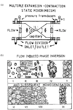
Figure 1-1 (a) Schematic drawing of a typical Multiple Expansion Contraction Static Mixer (MECSM) labeled with parts. (b) The proposed mechanism for flow-induced phase inversion of W/O emulsions into O/W emulsions divided into 9 steps. The shaded phase is the aqueous phase of the emulsions. Reproduced with permission from reference 23 ...6
Figure 1-2 Proposed mechanism of phase inversion of W/O/W multiple
emulsions into W/O emulsions inside a pore of polycarbonate membranes. Reproduced with permission from reference 27 ...7
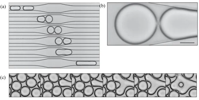
Figure 1-3 (a) Time sequence images showing two droplets as they pass through a ‘collision chamber’. As the droplets enter the wide part, they slow down and collide. However, coalescence does not occur upon collision. Coalescence is observed as the droplets separate from each other while they speed up into the narrow part of the channel. Top to bottom time in ms: 0, 3, 5, 7, 7.1, 10. Reproduced with permission from reference 28. (b) Formation of nipples on the surface of droplets due to low pressure in the interstitial film caused by separation of the droplets. (Scale bar is 20µm). Reproduced with permission from reference 28 (c) Time sequence showing propagation of droplet coalescence in 2-dimensional array of droplets showing encapsulation of continuous phase and local phase inversion. The small droplet in the final image is part of the continuous phase engulfed in between coalescing droplets. Mean drop radius is 20µm and each time step is 0.133ms. Reproduced with permission from reference 29 ...10
Figure 1-4 Macroscopic phase separation of O/W emulsions using droplet adhesion technology for recycling of emulsion droplets. Oil phase contains a red dye. Passing the O/W emulsions through a channel with hydrophilic and hydrophobic surface causes complete phase separation into oil and water phases. Reproduced with permission from reference 30. ...11
(b) 0.27mm/s adhesion of oil droplets to the channel surface, and (c) at 0.61mm/s inversion of O/W emulsions into W/O emulsions occurs. Reproduced with permission from reference 31 ...12
Figure 2-1 (a) Phase inversion of W/O emulsions into O/W emulsions when the
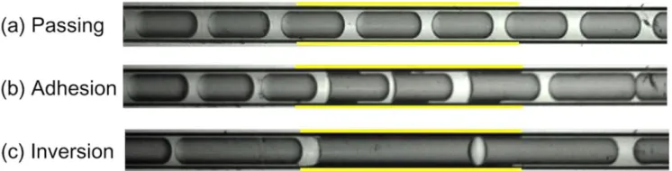
channel wettability is reversed from hydrophobic to hydrophilic. Water (bright) which is initially in droplet form becomes the continuous phase in the downstream hydrophilic part after reconfiguration of fluids in the transition region. Reproduced with permission from reference 6. (b) O/W emulsions (with oil phase dyed red) invert into W/O emulsions as they flow from the hydrophilic section into the hydrophobic section of the capillary. Reproduced with permission from reference 7 (c) Different outcomes of flowing O/W emulsions at different flow rates (Passing-2.61mm/s, Adhesion-0.27mm/s, Inversion-0.61mm/s) through a glass capillary channel with heterogeneous wetting conditions. The hydrophobic section is marked in yellow. Reproduced with permission from reference 8 ...23
Figure 2-2 (a) Image of the photo-mask showing one phase inversion channel. The circular end on the left is the inlet and the on the right is the outlet. The half-angle is 2.5o and the minimum channel width is 40µm. (b) A photograph of the device array fabricated by soft-lithography in PDMS showing 40 devices on one chip. The smallest division of scale at the bottom is 1/20th inch. ...25
Figure 2-3 (a) Schematic illustration of glass-capillary flow-focusing droplet generator (Blue = Aqueous, Yellow = Oil) showing the dimensions of the capillary orifices. The small orifice is ~40µm and the collection channel is roughly 200µm. White curved arrows show the direction of flow of continuous phase. (b) Optical microscopy image of the flow-focusing device during generation of O/W emulsions. ...29
Figure 2-4 Optical microscopy image of a PIC injected with a concentrated emulsion phase ...30
of dispersed phase between the emulsion and the non-wetting channel. Reproduced with permission from reference 6. ...32
Figure 2-6 Injection of O/W (left column) and W/O (right column) emulsions into hydrophilic (top row) as well as hydrophobic (bottom row) microchannels. PDMS is used for the hydrophilic while glass capillaries are used for the hydrophilic channels. Emulsions are injected under low Ca (~O(10-3)) conditions. O/W emulsions show no phase inversion in hydrophilic channels (case (a)), while they phase invert into W/O emulsions in hydrophobic channels (case (c)). Similarly, W/O emulsions show no phase inversion in hydrophobic channels (case (d)), while they phase invert into O/W emulsions in hydrophilic channels (case (b)). Therefore, wetting between dispersed phase and channel walls is necessary to induce phase inversion. ...34
Figure 2-7 (a) Schematic of PDMS phase inversion channel (PIC) showing the upstream wide part and the downstream tapered part. O/W emulsions (Blue-aqueous, Yellow-Oil) flowing through the PIC from left to right. (b) Tapered part of the channel with continuously varying width (W(x)) as compared to a combinatorial arrangement of many channels of decreasing widths W1 through W5. ...35
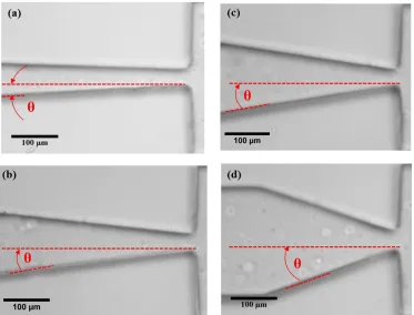
Figure 2-8 Optical microscopy images of phase inversion channels with increasing taper angles. Red curved arrows showing the taper half-angles (a)2.5o. (b) 7o. (c)9o. (d)20o. ...36
Figure 2-9 (a) State-plot generated by observing behavior of O/W emulsions at low Ca (~O(10-3)), at different taper angles of the phase inversion channels, ranging from 2.5o to 20o. Filled symbols represent PIE while open symbols represent no PIE. Likelihood of PIE becomes negligible over a critical taper angle (4.5-7o). (b) Aspect ratio of droplets in their most deformed state (either just before rupture, or just before exiting the tapered zone of PIC) plotted for different taper half-angles. The highest aspect ratio of droplets shows a decreasing trend with increasing taper angle. ...38
Figure 3-1 State plot between Ca vs. D/W showing two categories of process
outcomes. Green squares represent phase inversion events (PIE). One such PIE event is shown in inset (i). Red triangles represent no Phase inversion (No PIE). This can either lead to no change in emulsion phase (inset(ii)) or can lead to formation of O/W/O multiple emulsions (inset(iii)). Dashed curve (a.k.a. ‘separation curve’) is drawn to visually segregate the PIE and no PIE points except for a few outliers. ...52
Figure 3-2 Time-resolved images of a pair of oil droplets (droplet A in the front and a smaller droplet B in the back) showing O/W/O formation due to polydispersity of precursor emulsions. (a) t=0 ms, A and B are intact in the tapered part of PIC. (b) t=50ms, droplet A has undergone FIPIE. Arrow indicates the part of aqueous phase which was initially surrounding A, and is now an independent water droplet. (c) t=200ms, B escapes FIPIE and results in O/W/O double emulsions. White arrow shows the oil droplet B engulfed in aqueous phase ...55
Figure 3-3 (a) t=0ms, oil droplet flows into the tapered part of PIC. Red dashed curve shows that the initial curvature of O/W interface is concave towards the oil (droplet) phase. (b) t=2ms, The intercalating aqueous film surrounding the oil droplet ruptures by hole formation. Red arrow indicates the position of origin of the hole. (c) t=6ms, Hole enlarges and aqueous film retracts due to interfacial tension. Contrast difference clarifies the position of the film and film border showing how much retraction has occurred. (d) t=8ms, red dashed curve is shown to mark the outline of the retracting film (e) t=38ms, retraction results in the formation of secondary water droplets from the film-fluid.. (f) t-138ms, O-W interface relaxes to minimize energy. Final curvature of the interface is concave towards aqueous phase as evidence for completion of phase inversion (g) Optical micrograph of PIC with fluorescently labeled oil phase showing the presence of thin ‘lubrication’ film of oil along the walls of the hydrophobic PIC walls. ...58
the aqueous film shows the location of the retraction front. (d) After complete retraction and relaxation of the interfaces, W/O emulsions exit the PIC. Oil #1 is now part of the continuous phase and the process repeats with Oil droplet #2. ...60
Figure 3-5 A best-fit line, representing the line separating PIE and no PIE regions, is drawn on the Ca*W3/4 vs. D/w plot. The slope (0.74) of the best-fit line closely matches the expected value (0.75) from the scaling arguments in Eq. 2. ...62
Figure 4-1 (a) Molecular structure of Tween 20 and (b) General structure of PEO-PPO-PEO block copolymers a.k.a. Pluronics with block lengths a (PEO) and b(PPO). By varying a,b the properties of Pluronics can be significantly changed. Images reproduced from wikipedia.org ...68
Figure 4-2 “Pluronic Grid” showing the wide-variety of commercially available
Pluronic surfactants. The PEO% are plotted on the x-axis in increments of 10% and the MW of PPO blocks are plotted on the y-axis. The Pluronics used in this study (Series 1-F108, F98, F68, Series 2-P104, P84, L64) are highlighted with bold circles on the grid. Reproduced with permission from reference 7 ...69
Figure 4-3 Droplet size vs. Qcontinuous/Qdispersed for Pluronic F68 solution at 10
times CMC concentration. ...73
Figure 4-4 Interfacial tension of Pluronic surfactants as a function of time. Concentrations of each Pluronic is ~10 times their respective CMCs obtained from literature. Interfacial tension at the end of 1 hour is used as the ‘equilibrium’ interfacial tension because of high concentration. For comparison, the dotted line shows the interfacial tension between light mineral oil and 1% wt. Tween 20 molecular surfactant used in previous chapters ...76
Figure 4-6 Comparison of rupture frequency of O/W emulsions in PICs as a function of Ca, at D/W ~ 5. Lower rupture frequency signifies emulsions are less susceptible to FIPIE. Three Pluronic surfactants of constant PPO/PEO and increasing MW in the order (a) Series 1: F68<F98<F108. (b) Series 2: L64<P84<P104 ...81
Figure 4-7 (a) Comparison of rupture frequency (Lower = more stable) of O/W
emulsions in PICs as a function of Ca, at D/W ~ 5 for pairs of Pluronic surfactants with same PPO chain length (NPPO) but increasing PEO chain lengths (NPEO) i.e. increasing PEO/PPO in the order (a) L64<F68, (b) P104<F108 ...82
Figure 5-1 Optical microscopy image of polydisperse O/W emulsions flowing through a hydrophobic glass capillary PIC/ Larger droplets show the film-rupture while smaller droplets escape, forming O/W/O multiple emulsions. The size and relative position of droplets in the PIC determine the number of cores inside the multiple emulsions ...96
Figure 5-2 (a) Optical microscopy image of actuator-equipped droplet generator. Increase in valve-pressure in the actuators causes them to expand and pinch on the collection channel of the droplet generator. (b) Variation of droplet sizes as a value pressure is increased. (c) Size of droplets generated at different valve-pressure conditions plotted as a function of the orifice width. Inset shows the frequency of droplet generation as a function of inverse of droplet volume. Since the volumetric flow rates are constant, smaller droplets (on the right) are generated at higher frequencies. Reproduced with permission from reference 1 ...97
Figure 5-3 (a) Schematic illustration of the effect of polydispersity of precursor emulsions with a bimodal size distribution and synchronized injection into PICs. (a) When two large droplets are separated by one small droplet leading to O/W/O double emulsions. (b) more than one smaller droplets in between large droplets can result in O/W/O multiple emulsions. (c) Optical micrograph of synchronized droplet reinjection using two different sized droplets. Reproduced with permission from reference 2. ...98
Figure 5-5 Optical microscope images of PICs with channels added for injection of continuous phase i.e. the ‘spacer fluid’ between oil droplets to increase the inter-droplet distance (IDD). IDD increased with increasing flow rate of the spacer fluid from (a) through (c). ...101
Chapter 1
Introduction to Flow-Induced Phase Inversion
Emulsification (FIPIE)
1.1 Introduction and Motivation
Emulsions are multi-phasic liquid mixtures in which droplets of one liquid are
dispersed in another immiscible liquid. They are essential components of
numerous products we use daily, natural as well as man-made, such as milk, salad
dressing, cosmetics and paints. The characteristics of emulsions are closely
correlated with the formulation and composition of the emulsion system, as well
as the emulsification technique used to generate them. Emulsification techniques
are broadly classified into two kinds: high-energy and low-energy emulsification.
While high-energy techniques rely on huge amounts of energy input in the form
of high-intensity stirring or high-pressure homogenizations, low-energy
techniques achieve the same outcome by changing the thermodynamics or
dynamics of emulsification, such as by changing the surfactant/oil/water
composition of the system. However, lack of proper fundamental understanding
of the energy methods limits their widespread application. One such
low-energy technique is called phase inversion emulsification (PIE).
PIE is an emulsification process where the continuous and dispersed phases of a
pre-existing emulsion are interchanged like the generation of a water-in-oil
emulsion from a pre-existing oil-in-water emulsion. But why would we use this
emulsification, such as nanoemulsions, which are emulsions with droplet sizes in
the range of 100-200nm. Low viscosity and transparent visual aspects of
nanoemulsions make them attractive for applications in the food industry. High
surface area, which allows an effective transport of active ingredients to the skin
and other parts of the body, motivate cosmetic and pharmaceutical applications.1
Naturally, due to high surface area, synthesis of nanoemulsions requires enormous
amounts of energy inputs during emulsification. For applications such as
synthesis of nanoemulsion-templated nanoparticles, often monomers of high
viscosity are emulsified, which further increases the magnitude of energy
required.2 Phase inversion temperature (PIT) method, a particular mechanism of
PIE, has been shown to generate nanoemulsions at a fraction of energy
consumption as compared to conventional emulsification techniques.3-5 Another
mechanism of PIE, called the catastrophic PIE is one of the core technologies that
many companies (e.g., Xerox) uses to generate latex particles by inverting a W/O
emulsion to an O/W emulsion.6 Latex particles from these resin emulsions form
the raw materials for Xerox products such as toners that are used in
electro-statographic applications.7 PIE processes also have been used by pharmaceutical
and food industry to prepare emulsions with desirable properties (e.g., small size,
shelf-life, flowability etc.).8-10
A majority of PIE applications in industry are currently performed as batch or
continuous mode. Ease of automation is another factor favoring the introduction
of continuous processing. Many studies, in fact, have demonstrated considerable
reductions in operation time/cost by changing a batch/semi-batch system to a
continuous system.10 The pharmaceutical industry, which traditionally used
batch-wise processes, is now aggressively shifting its manufacturing paradigm toward
continuous processes to further reduce cost, improve process efficiency and
flexibility in production capacity.11 The Food and Drug Administration’s Center
for Drug Evaluation and Research (CDER) has emphasized the need for active
research in this field through a new house bill to award grants for
university-industry collaborative projects, such as the MIT-Novartis Center for Continuous
Manufacturing.12 Increasing number of pharmaceutical companies, such as
GlaxoSmithKline, Johnson & Johnson and Vertex Pharmaceuticals are now
making serious financial commitments because of the obvious benefits of
continuous processing in the long run. The limited understanding and know-how
of continuous PIE is a stumbling block in this path and warrants a systematic
in-depth investigation.
Typically, PIE is either induced by increasing the dispersed-to-continuous phase
ratio in the emulsion, a.k.a catastrophic PIE,13-17 or by changing the affinity of the
emulsifiers towards the two fluid phases, which is known as transitional PIE.18-21
Most PIE processes are accompanied by a reduction in the overall free energy of
barrier between the initial and final states. Processes such as catastrophic PIE
overcome that barrier by delivering mechanical energy using industrial mixer
units. This energy input requirement, along with the requirement for the addition
of the dispersed phase, has traditionally been achieved using vessels fitted with
impellers in batch systems. To drastically change this approach to enable
continuous PIE, an under-explored flow-induced PIE (FIPIE) technique is being
investigated in this thesis. In FIPIE, the energy required to overcome the energy
barrier is provided through shear deformation of the emulsions as they flow
through precisely engineered channels.23 One clear advantage of using FIPIE
mechanism is that it can be simulated in microfluidic channels and thus direct
observation and fundamental investigation of the PIE process is possible.
1.2 Flow-induced phase inversion emulsification: state-of-the-art
In the early 1990s’ a few patents and papers showed that PIE of W/O emulsions
can be induced by flowing emulsions through a multiple expansion contraction
static mixer (MECSM, Figure 1-1(a)). Multiple passes of coarse starting W/O
emulsions through the expansion-contraction geometry of the static mixer resulted
in phase inversion into O/W emulsions.23, 24 Several design parameters of the
MECSMs such as the length and width of the narrow constriction (~100s’ μm)
and entry/exit angles of the constriction were varied in the study. The length and
diameter of the capillary were found to be important geometrical factors and were
drop deformation induced by shear and extensional rates on the passing emulsion
was found to be important.
Based on the existing knowledge of behavior of structured fluids, such as
colloidal suspensions, in converging/diverging flow conditions, a mechanism for
FIPIE in MECSMs was proposed. When deformable particles such as emulsion
droplets are accelerated through a constriction, the particle shape changes to
cylindrical rods with their long axis aligned along the flow direction (II in Figure
1-1(b)).25, 26 When the fluid exits the constriction, the droplets transform into
disc-like shapes (III in Figure 1-1(b)), due to deceleration of flow and sudden
expansion. This sudden change is accompanied by a marked inversion in the
interfacial curvature (concave-to-convex), which is believed to be the hallmark of
PIE processes. It was proposed that these deformed disc-shaped water droplets
aggregate and encapsulate the continuous phase (oil) (IV in Figure 1-1(b)). The
presence of smaller water droplets suspended in the oil phase facilitates aqueous
encapsulation of oil droplets as more water discs aggregate around the oil droplets
(IV & V in Figure 1-1(b)). Through this process, the continuous phase changes
from oil to water (V in Figure 1-1(b)). PIE is considered to be partially complete
with the formation of multiple emulsions (W/O/W) (VI in Figure 1-1(b)). In
subsequent passes through the MECSM (VII in Figure 1-1(b)), the compound oil
droplets (containing the aqueous phase droplets i.e. W/O/W emulsions) undergo
6
the oil phase thereby causing a relatively easier fragmentation of the oil phase
during subsequent passes, leading to complete phase inversion to O/W emulsions
(VII & IX in Figure 1-1(b)).
This study demonstrated that under appropriate flow conditions, PIE can be
induced without changing the thermodynamic state (temperature or composition)
of the system. Even though FIPIE of W/O emulsions in MECSM provided a
proof-of-principle, very limited fundamental understanding of FIPIE was
developed. It is our hypothesis that due to the high surface area to volume ratio at
the small length-scales involved in this process, wetting conditions of the
materials used to fabricate the MECSM could significantly affect FIPIE.
Likewise, the morphology and chemistry of the precursor emulsions are expected
to be very important in shaping the flow behavior as well as FIPIE of emulsions.
The mechanism proposed in these reports lacked fundamental droplet-level
information, and only provided speculations as to how PIE would occur as
emulsions flowed through constrictions and expansions.
In another study on shear-induced phase inversion, water-in-oil-in-water
(W/O/W) multiple emulsions were flowed through polycarbonate membranes
with pore sizes of 3 or 8µm.27 It was proposed that as the multiple emulsion
droplets squeezed through the membrane pores, a lamellar structure of
surfactant-laden interfaces was formed inside the pore, as shown schematically in Figure
1-2. Marangoni stresses developed inside the membrane pores, thus rupturing the
lamellar structures and forming reverse micelles. These reverse micelles
coalesced to form W/O emulsions. The mixing ratio of hydrophilic to
hydrophobic surfactants was reported to affect whether the system would undergo
phase inversion. Additionally, reversal of the pore-wall wetting properties was
shown to generate different kinds of emulsions from the same W/O/W emulsions.
Hydrophilic membranes led to O/W emulsions while hydrophobic membranes
facilitated W/O emulsions. While the importance of wetting properties of
materials of constructions was highlighted, a fundamental understanding of FIPIE
on the single droplet-level was missing. A more systematic investigation of
geometric factors of the pore, which can facilitate this PIE would enable
continuous processing by this mechanism. The developments in the field of FIPIE
remained relatively slow in the subsequent years until recently when
advancements in microfluidic fabrication as well as high-speed imaging
techniques made it possible to observe the processes at the droplet-level.
previously known that the sudden acceleration of two droplets in close proximity
can lead to a reduction in pressure in the interstitial film between them, causing
coalescence (Figure 1-3(a)). This principle was utilized for a two-dimensional
array of emulsions, creating a cascade of propagative coalescence events that
ultimately lead to phase inversion (Figure 1-3(b)).29 Both size and spatial
distribution of droplets in the two-dimensional arrangement were shown to affect
the probability of coalescence. Observation of droplet-level events in real time led
to a better understanding of droplet motion and the propagation of coalescence
front, highlighting the importance of in situ observation in fundamental
investigations of processes with unclear mechanisms.
Recently, phase inversion of emulsions has been reported by changing the wetting
properties of micro-channels carrying the emulsion droplets.30 It was shown that
when O/W emulsions flowing through a hydrophilic channel suddenly enter a
hydrophobic region of the channel, droplets could adhere to the channel walls
depending on the Capillary number of the flow. A scaling relationship between
the critical Ca and the ratio of size of droplets to the size of channels was also
developed leading to a deeper understanding of the underlying physical
phenomena governing flow-behavior of emulsions through channels of changing
wettabilities. This study further reaffirmed the importance of wetting properties of
microchannels because these findings could enable recycling of the ingredient
10
in this study. Spatial site patterning of surface of glass capillaries with the help of
photolithographic techniques has been reported to significantly affect the
morphology and behavior of emulsions in the patterned micro-channels. It was
shown that by creating sharp contrasts in surface wettability, emulsions could
adhere to the channel surfaces, and invert phases (Figure 1-5).31 However, this
was only a proof-of-concept and no fundamental understanding of the factors
affecting phase inversion or the mechanistic steps involved in the process were
reported.
It is therefore clear that flowing emulsions through precisely designed channels or
membranes can induce phase inversion. The wetting properties of the channels
play a very significant role in this process and can be leveraged to trigger phase
inversion in specific locations inside these channels. However, a comprehensive
understanding of the design parameters necessary for enabling continuous FIPIE
is still elusive. A systematic investigation of the factors which affect the outcome
of the process, especially in terms of dimensionless quantities could prove to be
very useful in the future scaling up of the process. Finally, it is essential to
develop the mechanistic understanding of the process is essential to fully utilize it
on a larger scale, which can be achieved through in situ observation of
droplet-level changes occurring during FIPIE.
1.3 Thesis Objectives and Outline
To enable continuous PIE with high reliability and control, it is imperative to
develop a more careful and systematic approach to study flow-induced PIE. The
goal of this thesis is to develop a single droplet-level understanding of FIPIE
using microfluidics. Microfluidic systems operate at low Reynolds numbers, i.e.
under laminar flow-conditions, just like systems involving high viscosity fluids.
Therefore, microfluidics was chosen to investigate the conditions for phase
inversion. Additionally, microfluidic droplet generation enables precise control on
the size, composition and characteristics of precursor emulsions, which is
necessary for a systematic study of the process. Finally, with the advancements in
high-speed imaging capabilities, in situ observation of FIPIE with high spatial and
temporal resolutions can give important insights into the mechanism of the
process.
Some of the fundamental questions about FIPIE addressed in this thesis are,
How does the channel geometry affect the interactions between
channel-surface and emulsion droplets?
Under what conditions is wettability of channel walls important in inducing
PIE?
What are the dynamic flow-conditions necessary to facilitate or prevent
FIPIE as per requirements?
What is the mechanism of the process? What is the most important step in
the mechanism?
What is the driving force, or the underlying physical phenomena in FIPIE?
The thesis is divided into three main sections. In the first section, (Chapter 2) we
optimized the design of the microfluidic phase inversion channels (PICs) in terms
of the geometry of the channel as well as the channel wetting properties. We
found that preferential wetting between the dispersed phase of the emulsions and
the channel walls was essential to induce phase inversion. We used variable-width
geometry of PICs to avoid the need for complicated surface wettability patterning.
The amount of channel taper was also found to be important in deciding the fate
of the precursor emulsions flowing through the PICs. With the help of this
understanding, we designed our PICs to efficiently and reliably induce phase
In the second section, (Chapter 3), we performed a fundamental investigation of
the FIPIE process. We investigated the dynamic factors affecting the process
outcome in terms of dimensionless parameters and expressed it in the form of a
state-diagram showing regions of operation for different outcomes. Next, we
utilized in situ high-speed imaging to gain insights into the mechanistic steps of
the process. We found that the rupture of the continuous phase thin film around
the droplets inside the PICs, was the most important step in FIPIE. We also
considered the effect of stress balance at the interface on the rupture of the thin
film. This analysis provided insights into the underlying physical phenomenon
and driving force behind FIPIE.
In the third section, (Chapter 4), we investigated the effect of the surfactants on
the rupture of the aqueous film, and thus on FIPIE. We used amphiphilic triblock
copolymers of PEO-PPO-PEO type, commercially available as Pluronic
surfactants in this study due to their versatility as well as their economical
availability with a wide range of properties. We found that emulsions stabilized
by Pluronic copolymers were more stable against FIPIE as compared to those
stabilized by the molecular surfactant (Tween20) used in the previous chapters,
even though the interfacial tensions were lower in the case of Tween 20. This
observation indicated other factors such as steric stabilization playing a crucial
role in the rupture of aqueous films, which was verified by varying the molecular
The understanding developed in this study brings us one step closer to the goal of
enabling continuous FIPIE in industry. However, various newer aspects of FIPIE,
which warrant further investigations, were highlighted. The findings of this thesis
are based on a limited set of S/O/W (surfactant/oil/water) systems. In order to
generalize these findings, the effects on different, industrially relevant systems are
necessary. One way to approach this problem would be to investigate the effect of
a dimensionless viscosity ratio (µc/µd) of the continuous and dispersed phases on
FIPIE. The emulsions used in this study were monodisperse with precise control
on their size and distribution. While this was necessary for a systematic
investigation, this tight control on precursor emulsions is unrealistic. In fact,
polydispersity of precursor emulsions, as briefly discussed in Chapter 3, could
change the outcome of FIPIE significantly. A study employing precursor
emulsions with controlled polydispersity could provide valuable insights into a
more realistic picture of FIPIE, especially on aspects such as multiple emulsion
References
1. Solans, C.; Izquierdo, P.; Nolla, J.; Azemar, N.; Garcia-Celma, M.,
Nano-emulsions. Current opinion in colloid & interface science 2005, 10, (3), 102-110.
2. Anton, N.; Benoit, J.-P.; Saulnier, P., Design and production of
nanoparticles formulated from nano-emulsion templates—a review. Journal of
Controlled Release 2008, 128, (3), 185-199.
3. Solans, C.; Solé, I., Nano-emulsions: formation by low-energy methods.
Current Opinion in Colloid & Interface Science 2012, 17, (5), 246-254.
4. Izquierdo, P.; Esquena, J.; Tadros, T. F.; Dederen, C.; Garcia, M.;
Azemar, N.; Solans, C., Formation and stability of nano-emulsions prepared using
the phase inversion temperature method. Langmuir 2002, 18, (1), 26-30.
5. Ostertag, F.; Weiss, J.; McClements, D. J., Low-energy formation of
edible nanoemulsions: factors influencing droplet size produced by emulsion
phase inversion. Journal of colloid and interface science 2012, 388, (1), 95-102.
6. Mathiowitz, E.; Chickering III, D.; Jong, Y. S.; Jacob, J. S., Process for
preparing microparticles through phase inversion phenomena. In Google Patents:
2001.
7. Zhou, K.; Qiu, S. S.; Moffat, K. A.; Sacripante, G. G., Solvent-free phase
inversion process for producing resin emulsions. In Google Patents: 2011.
8. Garti, N., Progress in stabilization and transport phenomena of double
emulsions in food applications. LWT-Food Science and Technology 1997, 30, (3),
9. Matsumoto, S.; Koh, Y.; Michiure, A., Preparation of w/o/w emulsions in
an edible form on the basis of phase inversion technique. JOURNAL OF
DISPERSION SCIENCE ANDTECHNOLOGY 1985, 6, (5), 507-521.
10. Thakur, R. K.; Villette, C.; Aubry, J.; Delaplace, G., Dynamic
emulsification and catastrophic phase inversion of lecithin-based emulsions.
Colloids and Surfaces A: Physicochemical and Engineering Aspects 2008, 315,
(1), 285-293.
11. Vervaet, C.; Remon, J. P., Continuous granulation in the pharmaceutical
industry. Chemical Engineering Science 2005, 60, (14), 3949-3957.
12.
http://www.in-pharmatechnologist.com/Processing/FDA-calls-on-manufacturers-to-begin-switch-from-batch-to-continuous-production (8/15/2016),
13. Brooks, B.; Richmond, H., Phase inversion in non-ionic surfactant—oil—
water systems—II. Drop size studies in catastrophic inversion with turbulent
mixing. Chemical engineering science 1994, 49, (7), 1065-1075.
14. Mira, I.; Zambrano, N.; Tyrode, E.; Márquez, L.; Peña, A. A.; Pizzino, A.;
Salager, J.-L., Emulsion catastrophic inversion from abnormal to normal
morphology. 2. Effect of the stirring intensity on the dynamic inversion frontier.
Industrial & engineering chemistry research 2003, 42, (1), 57-61.
15. Salager, J.-L.; Márquez, L.; Peña, A. A.; Rondón, M.; Silva, F.; Tyrode,
E., Current phenomenological know-how and modeling of emulsion inversion.
16. Salager, J.-L.; Forgiarini, A.; Marquez, L.; Pena, A.; Pizzino, A.;
Rodriguez, M. P.; Rondon-Gonzalez, M., Using emulsion inversion in industrial
processes. Advances in colloid and interface science 2004, 108, 259-272.
17. Vaessen, G.; Stein, H., The applicability of catastrophe theory to emulsion
phase inversion. Journal of colloid and interface science 1995, 176, (2), 378-387.
18. Brooks, B. W.; Richmond, H. N., Phase inversion in non-ionic
surfactant—oil—water systems—I. The effect of transitional inversion on
emulsion drop sizes. Chemical engineering science 1994, 49, (7), 1053-1064.
19. Förster, T.; Schambil, F.; Von Rybinski, W., Production of fine disperse
and long-term stable oil-in-water emulsions by the phase inversion temperature
method. Journal of dispersion science and technology 1992, 13, (2), 183-193.
20. Allouche, J.; Tyrode, E.; Sadtler, V.; Choplin, L.; Salager, J.-L.,
Simultaneous conductivity and viscosity measurements as a technique to track
emulsion inversion by the phase-inversion-temperature method. Langmuir 2004,
20, (6), 2134-2140.
21. Shinoda, K.; Saito, H., The stability of O/W type emulsions as functions
of temperature and the HLB of emulsifiers: the emulsification by PIT-method.
Journal of Colloid and Interface Science 1969, 30, (2), 258-263.
22. Dickinson, E., Thermodynamic aspects of emulsion phase inversion.
Journal of Colloid and Interface Science 1982, 87, (2), 416-423.
23. Akay, G., Flow-induced phase inversion in the intensive processing of
24. Akay, G., Stable oil-in-water emulsions and a process for preparing same.
European Patent 1995, 649, (867), A1.
25. Leslie, F., Hamel flow of certain anisotropic fluids. Journal of Fluid
Mechanics 1964, 18, (04), 595-601.
26. Welch, C. F.; Rose, G. D.; Malotky, D.; Eckersley, S. T., Rheology of
high internal phase emulsions. Langmuir 2006, 22, (4), 1544-1550.
27. Kawashima, Y.; Hino, T.; Takeuchi, H.; Niwa, T.; Horibe, K.,
Shear-induced phase inversion and size control of water/oil/water emulsion droplets
with porous membrane. Journal of colloid and interface science 1991, 145, (2),
512-523.
28. Bremond, N.; Thiam, A. R.; Bibette, J., Decompressing emulsion droplets
favors coalescence. Physical review letters 2008, 100, (2), 024501.
29. Bremond, N.; Doméjean, H.; Bibette, J., Propagation of drop coalescence
in a two-dimensional emulsion: A route towards phase inversion. Physical review
letters 2011, 106, (21), 214502.
30. Chen, H.; Dong, E.; Li, J.; Stone, H. A., Adhesion of moving droplets in
microchannels. Applied Physics Letters 2013, 103, (13), 131605.
31. Zhang, Y.; van Nieuwkasteele, J. W.; Qiang, M.; Tsai, P. A.; Lammertink,
R. G., Spatial Site-Patterning of Wettability in a Microcapillary Tube. ACS
Chapter 2
Design of Phase Inversion Channels – Geometric and
Wetting properties
2.1 Abstract
In this chapter, the effects of properties of the phase inversion channels (PICs)
such as the wettability of channel surfaces and their geometric characteristics, on
flow-induced phase inversion of emulsions (FIPIE) have been investigated. It was
shown that preferential wetting between the dispersed phase of the precursor
emulsions and the PIC surface was crucial for inducing PIE. This was confirmed
by demonstrating FIPIE of O/W emulsions in hydrophobic PICs as well as W/O
emulsions in hydrophilic PICs. Recognizing the limitations of surface wettability
patterning techniques such as added complexity of fabrication, susceptibility to
erosion and a limited achievable contrast in wettability, a tapered design was
proposed to leverage relatively simpler homogeneous surface treatments. FIPIE
was shown to be very sensitive to the amount of taper and a cut-off taper angle
(~5o) was shown to exist. Above this cut-off angle FIPIE was suppressed. This
sensitivity could be correlated with the rapid reduction in the residence time of
droplets in the PIC with increasing taper angle.
2.2 Introduction
With recent advances in design and fabrication techniques, ‘lab-on-a-chip’
microfluidic devices have become popular model systems in a host of
interest, along with in situ real-time imaging. As a result, a microfluidic system
was chosen to investigate the fundamental mechanism and factors affecting
FIPIE. Iterative improvements in the design of microfluidic phase inversion
channels (μ-PICs) helped in optimizing the geometric and surface properties
favorable to induce PIE of O/W emulsions.
While designing microfluidic channels for different applications, several
parameters based on the understanding of the interactions between structured
fluids such as emulsions and the geometry and wetting properties of the channels
need to be considered.2, 3 The most important design parameters considered in this
study were cross-sectional shape, dimensions and wettability of the channels.
Simple rectangular (for PDMS) and cylindrical (for glass) geometries were used
throughout the study to avoid the need for complex fabrication techniques. The
channel height was kept between 1-2 times the droplet sizes in order to maintain
single droplet-level image clarity by avoiding droplet stacking. The channel width
tapered from an initial maximum width of 250µm, which is greater than all
droplet diameters used in the study, to a minimum of 25-40µm at a specific taper
angle (maintained between 2.5o-20o). The material properties of photoresist (SU-8
3050) as well as PDMS used in the photo- and soft-lithographic techniques
limited the maximum channel height/width ratio to 10:1.4 Downstream from the
Wetting properties of microfluidic channels significantly affect the flow
characteristics because of the high surface area – to – volume ratio typical at
micron length-scales.5 In fact, the nature of emulsions generated in microfluidic
droplet generators can be reversed e.g. from O/W to W/O, without changing the
surfactant/oil/water system, simply by reversing the wetting properties of the
channel walls. Similar wetting reversal was also used to induce the inversion of
emulsion for the first time, as shown in Figure 2-1(a).6 Later, Chen et al. showed
that phase inversion of pre-generated emulsions can be achieved by patterning the
channel wettability such that it preferentially wets the dispersed phase of the
injected emulsions (Figure 2-1(b)).7 Spatial site-patterning of glass capillaries
using lithographic techniques to achieve sharp contrasts in wettability has also
been shown to cause the inversion of emulsions under appropriate flow-conditions
as shown in Figure 2-1(c).8 However, a continuous operation of stable
flow-induced inversion of emulsions is necessary to enable continuous PIE for
applications. Additionally, other process parameters affecting the FIPIE need
rigorous investigation before the process can be scaled up.
In order to address these issues, the wettability and geometric parameters of phase
inversion channels (PICs) were investigated in this study to provide a blueprint
for the design of PICs. O/W and W/O emulsions were generated and flowed
through hydrophilic as well as hydrophobic PICs. It was shown that preferential
tapered downstream part. This design enabled localization of FIPIE in the tapered
part of the channel facilitating in situ observation. Finally, the amount of taper
was shown to be critical in determining the fate of emulsions flowing through the
PICs.
2.3 Experimental details
2.3.1 Photo-Lithography and Soft-Lithography
PICs were fabricated using photo- and soft-lithographic techniques. First, CAD
software (AutoCAD) was used to create designs of the PICs with exact
dimensions. These designs were printed, in negative, at 24,500 DPI, with a
minimum feature resolution of 10µm (CAD/Art Services, outputcity). These
prints were ‘photo-masks’ for the negative photoresist (SU-8 3050, Microchem)
during lithography. One such photo-mask is shown in Figure 2-2(a). Photoresist
was spin-coated on a silicon wafer. The thickness of the resist determines the final
height of the PICs. The spin-coating parameters were manipulated to maintain the
height of PICs between 1-2 times the size of droplets.9 For droplets ranging from
80-200µm, the height of the channels needed to vary between 100-220µm. The
photoresist was then exposed to UV radiation through the photo-mask
cross-linking the required regions. The uncross-linked photoresist was washed away
using the SU-8 developer (Microchem) to leave the negative replica of PICs on
the silicon master. This master was then hard baked to complete the cross-linking
process. To ensure that PDMS can be easily peeled from the surface of the master,
self-assembled monolayers of a fluorosilane
(Trichloro(1H,1H,2H,2H-perfluorooctyl)silane (Sigma)) were vapor-deposited on the wafer. 40µL of the
silane solution was placed in a desiccator with the wafer for 2 hours to facilitate
The base and cross-linking agent (Sylgard 184, Dow Corning) were measured in
the ratio 1:9 by weight, thoroughly mixed and placed in a desiccator for 1 hour to
remove any air bubbles. It was then poured on the silicon master and was placed
in an oven at 70oC for 2 hours to complete the cross-linking. Part of the PDMS
directly on top of the devices was cut with a sharp x-acto knife. Holes were
punched for the inlet and outlets of the fluids with a biopsy punch. The side of
PDMS with the features was delicately cleaned with scotch tape to remove any
physical residue. It was then exposed to O2 plasma for 90 seconds at 90W
(Harrick Plasma) alongside another thin layer of PDMS deposited on a glass slide.
The two ‘active’ PDMS surfaces were then bonded together with force and placed
in the oven at 70oC and left for 1 hour. These devices were then retrieved from the
oven and surface functionalization with OTS in hexadecane was performed. A
picture of the completed device array with 40 devices is shown in Figure 2-2(b).
2.3.2 Functionalization for glass capillary droplet generators
The surface tension between the fluids and the solid surface of microchannels
often plays a very crucial role in the flow-behavior of fluids. It is therefore, often
necessary to employ suitable surface functionalization on micro-channel surfaces
to obtain a stable flow condition. In this study, both O/W as well as W/O
emulsions were generated by glass capillary microfluidic devices. Since glass is
hydrophilic, no additional surface treatment was necessary for the generation of
O/W emulsions. However, the generation of W/O emulsions called for
hydrophobic functionalization of all inner surfaces. This was achieved by
functionalization of glass capillaries with self-assembled monolayers of
Trichloro(octadecyl)silane (OTS, Sigma). Clean glass capillaries were dipped in a
1vol.% solution of OTS in toluene for 90 seconds. After flushing out the
remaining OTS solution, the capillaries were washed with fresh toluene to remove
the unattached OTS, and then dried with N2. Care was taken to minimize
exposure to moisture, which could lead to side reactions of OTS resulting in white
residue on the capillaries. Finally, to facilitate chemical bonding of the silane to
glass, the capillaries were heated on a hot plate at 150oC for 2 hours. Sessile drop
tensiometry was used to characterize the functionalization using glass slides
functionalized by the same protocol. The three phase contact angle of an oil drop
in a continuous aqueous phase was found to be 114o±6.5o. Surface
functionalization was performed after the glass capillaries were tapered because
compromise the organic SAMs and reduce the effectiveness of the
functionalization.
2.3.3 Functionalization of PDMS phase inversion channels
PDMS is inherently hydrophobic because of surface methyl groups. However,
irradiation of the surface with O2 plasma alters the physical and chemical
structure of the surface.10 Methyl groups are oxidized, resulting in Si-OH groups
on the surface. This ‘glass-like’ surface enables functionalization as well as
chemical bonding between the different parts of the device. Additionally, the
Silanol (Si-OH) groups make the surface hydrophilic. This hydrophilic property is
short lived, and through the diffusion of oligomers of PDMS from the bulk to the
surface, the hydrophobicity is recovered, but rarely to the complete extent. This
recovery is however, slow and the kinetics is dependent on the storage conditions
(dry vs. wet, hot vs. cold). In order to reliably obtain a hydrophobic surface of
PDMS inside the phase inversion channels, the surface of PDMS was
functionalized with OTS briefly after plasma oxidation. A 1% (by vol.) solution
of OTS in hexadecane was injected into the PDMS device one hour after plasma
oxidation. This delay was essential to prevent unbonding or leakage of the freshly
assembled device. The OTS solution was allowed to sit in the channel for 15
minutes, at which point it was flushed out and replaced with a fresh solution for
another 15 minutes. Finally, a copious amount of ethanol was used to flush the
revealed the hydrophobic nature of OTS functionalized PDMS surface with
contact angle of 103o± 2.6o.
2.3.4 Microfluidic Droplet Generator Fabrication and Operation
Generation of a model emulsion system with precise control on size and
size-distribution is essential for a systematic study of FIPIE. This was achieved using
microfluidic glass capillary droplet generators. The design of the flow-focusing
device can be seen in Figure 2-3(a,b). Cylindrical glass capillaries were heated
coaxially and pulled to create a taper using a micropipette puller (Sutter
Instruments, P1000). The tips of these tapered capillaries were then precisely
forged using a micro-forge to create orifices of two different dimensions, as
shown in Figure 2-3(a).11 The glass capillaries were then functionalized with
OTS to help generate W/O emulsions. No such functionalization was necessary
for O/W emulsions. Both the cylindrical capillaries (large and small) were then
inserted coaxially into a square bore glass capillary facing each other. To ensure a
snug-fit, the inner dimensions of the square capillaries were chosen to closely
match the outer dimensions of the cylindrical capillaries. Care was taken to ensure
spatial alignment of the orifices of the cylindrical capillaries in all three (x-, y-
and z-) directions. Needles for the injection of fluids were then attached with
epoxy glue to make sure the channel was watertight. The glass capillary droplet
generators were allowed to dry and set before they were used.
inlets using syringe pumps (Harvard Aparatus). Initially, the flow rates of the
fluids were kept low (~100μl/h for dispersed and 1000 μl/h for continuous phase)
until both the continuous and dispersed phases reached the tip of the tapered
capillary and droplet generation began. The operation parameters for the dripping
regime were determined using the relationship between the Capillary number of
the outer phase and the Weber number of the inner phase.12 The flow-rates of
continuous and dispersed phases (Qc/Qd) were used to control the size of
droplets.
2.3.5 Droplet Reinjection
The droplet generation and phase inversion were studied in two separate devices
since both processes were flow-rate sensitive. Decoupling enabled the
independent investigation of a wide range of flow conditions. This required
collection of droplets from the generators and re-injecting them into the phase
inversion channels (PICs). This was challenging, especially for larger ‘fragile’
droplets (>100µm), because they were found to breakdown into smaller droplets
before they reached the tapered part of the PICs. Random breakdown of bigger
droplets led to uncontrolled polydispersity in the system and also reduced the
D/W, which was hindered FIPIE. To avoid this, the emulsions were collected in a
long piece of polyethylene tubing and transferred into the PICs directly from the
tubing. This way, the droplets are exposed to a minimum change of environment
(shear, wettability and cross-section) before they enter the PICs. Additionally,
collection in tubing minimized the exposure of emulsion phase to
dust/contaminants, which could clog the PICs and cause unnecessary pressure
drop.
The collection tubing, roughly 50-70cm in length was connected to the droplet
generator for 60 minutes, to fill the tube completely with emulsions. Then the
tubing was sealed at one end and suspended vertically to allow droplets to cream
to the top and form concentrated emulsion phase. The tubing was then connected
to the PICs. This way, concentrated emulsions with closely packed droplets were
delivered into the PICs (Figure 2-4). The behavior of droplets inside PICs was
found to depend on local hydrodynamic conditions. So, to subject each droplet to
similar conditions, it was essential to maintain a uniform inter-droplet distance.
Injection of closely packed droplets was therefore essential. Droplet reinjection is
an area of active scientific interest and interested readers can find more
information about the state-of-the-art from Ref 9, 13.The volumetric flow-rate of
reinjection determines the speed of droplets inside the PICs and therefore their
Ca. The flow-rate was varied from 20-20,000µL/h.
2.4 Results & Discussion
2.4.1 Relationship between channel wettability and FIPIE
Flow behaviors of emulsions and foams are dominated by the solid-fluid wetting
properties.5, 6, 14-17 Based on the discussion by Shui et al., flowing emulsions
through microchannels in which the channel is preferentially wetted by the
dispersed phase leads to creation of extra fluid-fluid interfaces, making it
energetically unfavorable and thermodynamically unstable. As shown in Figure